2016 MERCEDES-BENZ AMG GT ROADSTER tow
[x] Cancel search: towPage 249 of 289
Vehicle tool kit
General notes Apart from some country-specific variants, vehi-
cles are not equipped with tyre-changing tools.
If the vehicle is equipped with tyre-changing
tools, these are located in the left-hand stowage compartment behind the service flap in the lug-gage compartment. Some tools for changing a
wheel are specific to the vehicle. For more infor-
mation on which tyre changing tools are
required and approved to perform a wheel
change on your vehicle, consult a qualified spe-
cialist workshop.
Necessary tyre-changing tools can include, for
example:
R jack
R wheel chock
R wheel wrench
R ratchet ring spanner
R centring pin
i The jack weighs approximately 1.2 kg.
The maximum load bearing capacity of the
jack can be found on the adhesive label on the jack.
The jack is maintenance-free. If there is a
malfunction, please contact a qualified spe-
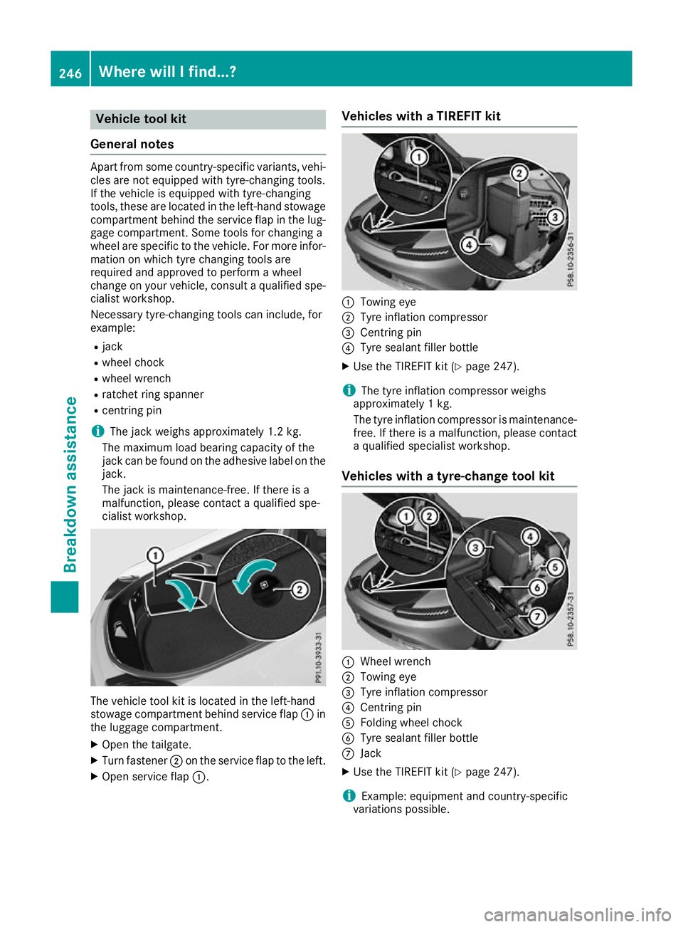
cialist workshop. The vehicle tool kit is located in the left-hand
stowage compartment behind service flap :in
the luggage compartment.
X Open the tailgate.
X Turn fastener ;on the service flap to the left.
X Open service flap :. Vehicles with a TIREFIT kit
:
Towing eye
; Tyre inflation compressor
= Centring pin
? Tyre sealant filler bottle
X Use the TIREFIT kit (Y page 247).
i The tyre inflation compressor weighs
approximately 1 kg.
The tyre inflation compressor is maintenance-
free. If there is a malfunction, please contact a qualified specialist workshop.
Vehicles with a tyre-change tool kit :
Wheel wrench
; Towing eye
= Tyre inflation compressor
? Centring pin
A Folding wheel chock
B Tyre sealant filler bottle
C Jack
X Use the TIREFIT kit (Y page 247).
i Example: equipment and country-specific
variations possible. 246
Where will I find...?Breakdo
wn assis tance
Page 251 of 289
Using the TIREFIT kit
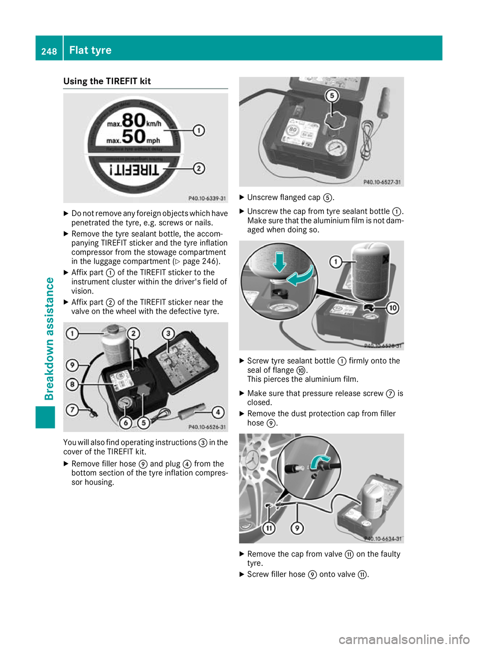
X
Do not remove any foreign objects which have
penetrated the tyre, e.g. screws or nails.
X Remove the tyre sealant bottle, the accom-
panying TIREFIT sticker and the tyre inflation
compressor from the stowage compartment
in the luggage compartment (Y page 246).
X Affix part :of the TIREFIT sticker to the
instrument cluster within the driver's field of
vision.
X Affix part ;of the TIREFIT sticker near the
valve on the wheel with the defective tyre. You will also find operating instructions
=in the
cover of the TIREFIT kit.
X Remove filler hose Eand plug ?from the
bottom section of the tyre inflation compres- sor housing. X
Unscrew flanged cap A.
X Unscrew the cap from tyre sealant bottle :.
Make sure that the aluminium film is not dam-
aged when doing so. X
Screw tyre sealant bottle :firmly onto the
seal of flange F.
This pierces the aluminium film.
X Make sure that pressure release screw Cis
closed.
X Remove the dust protection cap from filler
hose E. X
Remove the cap from valve Gon the faulty
tyre.
X Screw filler hose Eonto valve G. 248
Flat tyreBreakdown assistance
Page 253 of 289
Therefore, place the filler hose in the plastic
bag which contained the TIREFIT kit.
H
Environmental note
Have the used tyre sealant bottle disposed of professionally, e.g. at a qualified specialist
workshop.
If a tyre pressure of 180 kPa (1.8 bar/26 psi) has been attained after five minutes:
X Switch off the tyre inflation compressor.
X Unscrew the filler hose from the valve of the
faulty tyre.
Leave the tyre sealant bottle attached to the
flange.
X Stow the tyre sealant bottle, the tyre inflation
compressor and the warning triangle.
X Pull away immediately.
X Stop after driving for approximately ten
minutes and check the tyre pressure with the
tyre inflation compressor.
The tyre pressure must now be at least
130 kPa (1.3 bar/19 psi). G
WARNING
If the required tyre pressure is not reached
after driving for a short period, the tyre is too badly damaged. The tyre sealant cannot
repair the tyre in this instance. Damaged tyres and a tyre pressure that is too low can signif-
icantly impair the vehicle's braking and driv-
ing characteristics. There is a risk of accident.
Do not continue driving. Contact a qualified
specialist workshop.
i In your vehicle, you will find a sticker with
the Mercedes-Benz Service24h telephone
number, e.g. on the B-pillar on the driver's
side.
X Correct the tyre pressure if it is still at least
130 kPa (1.3 bar/19 psi). See the tyre pres-
sure table on the fuel filler flap for values.
X To increase the tyre pressure: switch on
the tyre inflation compressor.
X To reduce the tyre pressure: open release
screw C. X
When the tyre pressure is correct, unscrew
the filler hose from the valve of the sealed
tyre.
X Screw the valve cap onto the tyre valve of the
sealed tyre.
X Unscrew the tyre sealant bottle from the tyre
inflation compressor.
X Drive to the nearest qualified specialist work-
shop and have the tyre changed there.
X Have the tyre sealant bottle replaced as soon
as possible at a qualified specialist workshop.
X Have the tyre sealant bottle replaced every
four years at a qualified specialist workshop. Battery (vehicle)
Important safety notes
Work on the battery, e.g. removing or fitting,
requires specialist knowledge and the use of
special tools. Therefore, always have work on
the battery carried out at a qualified specialist
workshop. G
WARNING
Work carried out incorrectly on the battery
can lead, for example, to a short circuit and
thus damage the vehicle electronics. This can lead to function restrictions applying to
safety-relevant systems, e.g the lighting sys-
tem, the ABS (anti-lock braking system) or the
ESP ®
(Electronic Stability Program). The oper-
ating safety of your vehicle may be restricted.
You could lose control of the vehicle, for
example:
R when braking
R in the event of abrupt steering manoeuvres
and/or when the vehicle's speed is not
adapted to the road conditions
There is a risk of an accident.
In the event of a short circuit or a similar inci- dent, contact a qualified specialist workshop
immediately. Do not drive any further. Always have work on the battery carried out at a
qualified specialist workshop.
Further information about ABS (Y page 54) and
ESP ®
(Y page 57). 250
Battery (vehicle)Breakdown assistance
Page 259 of 289
Vehicles with carbon engine cover:
X Replace the jump-starting connection point cover. Make sure all mountings for the fasteners are
positioned precisely behind the corresponding recesses in the cover.
X Press the fasteners into the mountings. Turn the fasteners by Õof a turn to engage.
All vehicles:
X Have the battery checked at a qualified specialist workshop.
Jump-starting is not considered to be a normal operating condition.
i Jump-starting cables and further information regarding jump starting can be obtained at any
qualified specialist workshop. Towing away and tow-starting
Important safety notes
G
WARNING
The rear axle locks when:
R the engine is not running
R the engine stalls while the vehicle is being
towed
R there is a malfunction in the voltage supply
or the vehicle's electrical system
There is a risk of an accident.
In the event of a breakdown, you should
always have the vehicle transported. G
WARNING
If the brake system or power steering is mal-
functioning and your vehicle is then towed
away, significantly more effort may be
required to steer and brake than is normally
required. There is a risk of an accident.
In such cases use a rigid towing bar. Before
towing away, make sure steering moves
freely. G
WARNING
When towing or tow-starting another vehicle
and its weight is greater than the permissible gross weight of your vehicle, the:
R towing eye may be torn off
R car/trailer combination may swerve or
even overturn
There is a risk of an accident. When towing or tow-starting another vehicle,
its weight should not be greater than the per- missible gross weight of your vehicle.
Details on the permissible gross vehicle weight
of your vehicle can be found on the vehicle iden-
tification plate (Y page 276).
! Use the key instead of the Start/Stop but-
ton when towing the vehicle.
Start the engine and keep it running. Turn the key to position 2in the ignition. Set the trans-
mission to Nusing the E-SELECT lever. Make
sure that you then leave the key in position 2.
Check the transmission position in the instru-
ment cluster.
! Make sure that the electric parking brake is
released. If the electric parking brake is faulty,
visit a qualified specialist workshop.
! Secure the tow rope or tow bar to the towing
eye only. The vehicle may otherwise be dam-
aged.
! When Active Brake Assist, Distance Pilot
DISTRONIC or the HOLD function is activated, the vehicle brakes automatically in certain
situations.
To avoid damage to the vehicle, deactivate
these systems in the following or similar sit-
uations:
R when towing away
R in a car wash
! Observe the following points when towing
with a tow rope:
R secure the tow rope on the same side on
both vehicles.
R make sure that the tow rope is not longer
than legally permitted. Mark the tow rope in 256
Towing away and tow-startingBreakdown assistance
Page 260 of 289
the middle, e.g. with a white cloth
(30 x 30 cm). This makes other road users
aware that a vehicle is being towed.
R only secure the tow rope to the towing eye.
R observe the brake lamps of the towing vehi-
cle while driving. Always maintain a dis-
tance so that the tow rope does not sag.
R do not use steel cables or chains to tow
your vehicle. You could otherwise damage
the vehicle.
! Do not use the towing eyes for recovery pur-
poses as this could damage the vehicle. If in
doubt, recover the vehicle with a crane.
! When towing, pull away slowly and
smoothly. If the tractive power is too high, the
vehicles could be damaged.
! Shift the automatic transmission to
Nand
do not open the driver's or front passenger's
door during towing. The automatic transmis-
sion may otherwise shift to position P, which
could damage both vehicles.
! You may tow the vehicle for a maximum of
50km. A towing speed of 50 km/h must not
be exceeded.
For towing distances over 50 km, the entire
vehicle must be lifted up and transported.
! Observe the transmission fluid temperature
(AMG menu) in the on-board computer when
towing. The transmission fluid temperature
must not exceed 120 †. If this occurs, you
must stop towing immediately.
! Tow-starting the vehicle is not permitted.
The transmission may otherwise be damaged.
Also observe the following notes: R Observe the legal requirements in each indi-
vidual country when towing.
R If the engine does not start, try jump-starting
it (Y page 253). Tow-starting the vehicle is not
permitted.
R If it is not possible to jump-start the vehicle,
have it transported to the nearest qualified
specialist workshop, e.g. a Mercedes-Benz
Service Centre.
If the vehicle can no longer be driven because of an accident or breakdown, you have the follow-
ing options:
R transporting the vehicle As a rule, you should have the vehicle trans-
ported.
R towing the vehicle with a tow rope or tow bar
Only tow the vehicle in exceptional cases. The
engine must be running if you tow the vehicle with a tow rope or tow bar.
If the vehicle has suffered transmission damage, have it transported on a transporter or trailer.
Observe the display messages in the instrument
cluster.
The battery must be connected and charged.
Otherwise, you:
R will not be able to switch on the ignition with
the Start/Stop button
R cannot start the engine
R cannot release the electric parking brake
R cannot shift the automatic transmission to
position N
Deactivate the automatic locking feature before
towing the vehicle (Y page 70). You could oth-
erwise be locked out when pushing or towing
the vehicle.
Deactivate tow-away protection before the vehi-
cle is towed away (Y page 61). Fitting/removing the towing eye
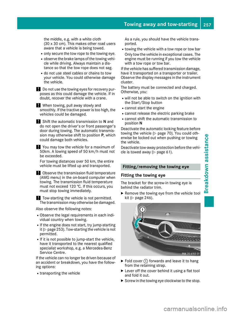
Fitting the towing eye The bracket for the screw-in towing eye is
behind the radiator trim.
X Remove the towing eye from the vehicle tool
kit (Y page 246). X
Fold cover :forwards and leave it to hang
from the retaining strap.
X Lever off the cover behind it using a flat tool
and fold it out.
X Screw in the towing eye clockwise to the stop. Towing away and tow-starting
257Breakdown assistance Z
Page 261 of 289
Removing the towing eye
X
Loosen the towing eye and unscrew it.
X Fold down the inner cover until it engages.
X Attach cover at the bottom and press it in at
the top until it engages.
X Put the towing eye back into the vehicle tool
kit. Towing the vehicle with all wheels on
the ground
It is important that you observe the safety
instructions when towing away your vehicle
(Y page 256).
The automatic transmission automatically shifts to position Pwhen you open the driver's or front-
passenger door or when you remove the key
from the ignition lock. In order to ensure that the automatic transmission stays in position N
when towing away the vehicle, you must
observe the following points:
X Insert the key into the ignition lock. You must
use the key instead of the Start/Stop button
(Y page 103).
X Start the engine and leave it running during
the entire towing procedure.
X Depress the brake pedal and keep it
depressed.
X Move the transmission to position Nwith the
E-SELECT lever.
X Check the transmission position using the
indicator in the multifunction display
(Y page 111).
X Release the brake pedal.
X Release the electric parking brake.
X Switch on the hazard warning lamps
(Y page 90).
In order to signal a change of direction when
towing the vehicle with the hazard warning
lamps switched on, use the combination switch as usual. In this case, only the turn signals for
the desired direction flash. When you reset the
combination switch, the hazard warning lamps
start flashing again. Transporting the vehicle
!
When the vehicle is loaded for transport, the
front and rear axles must be stationary and on the same transportation vehicle. Positioning
over the connection point of the transport
vehicle is not permitted. The drive train may
otherwise be damaged.
! You may only secure the vehicle by the
wheels, not by parts of the vehicle such as
axle or steering components. Otherwise, the
vehicle could be damaged.
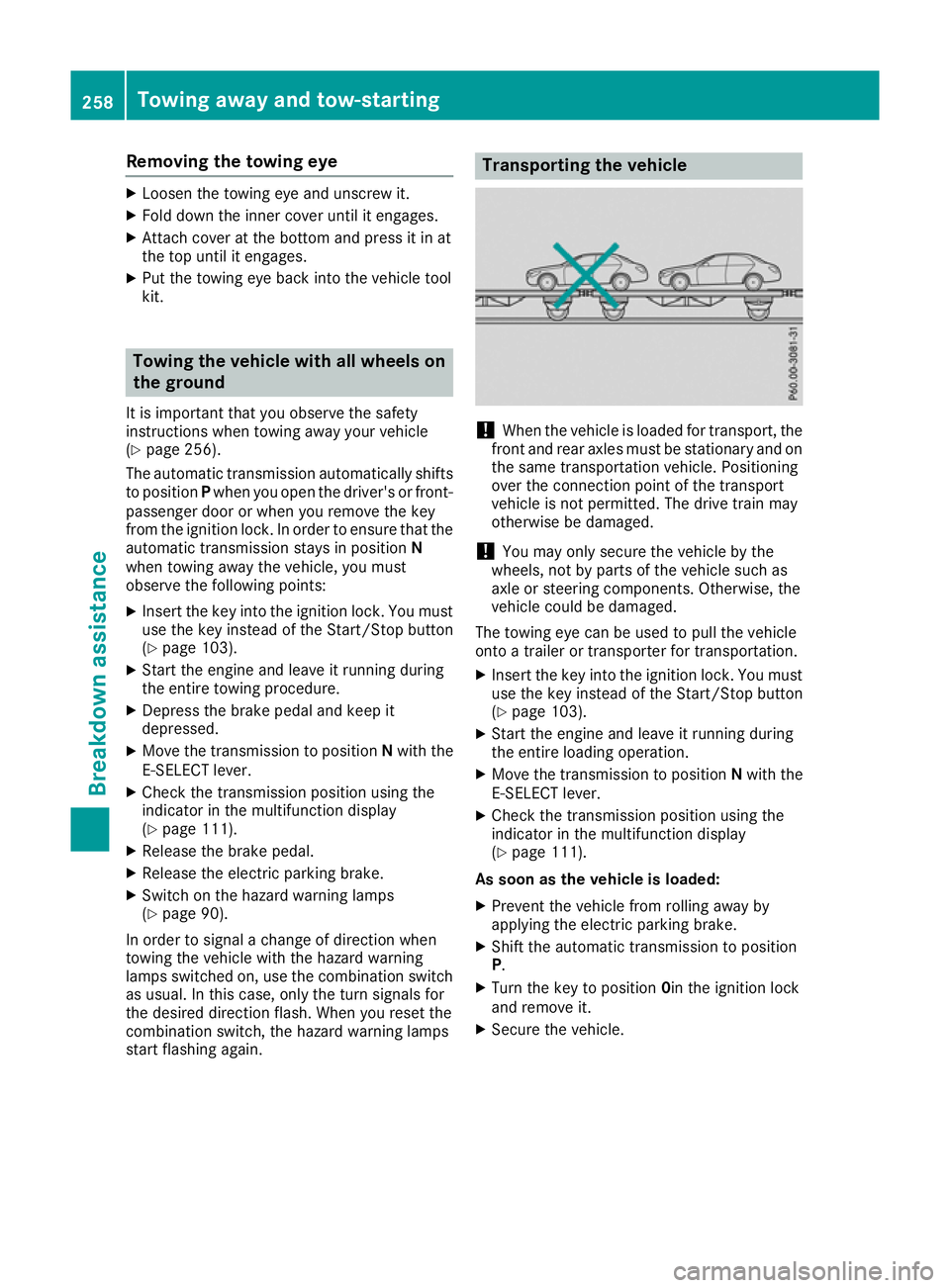
The towing eye can be used to pull the vehicle
onto a trailer or transporter for transportation.
X Insert the key into the ignition lock. You must
use the key instead of the Start/Stop button
(Y page 103).
X Start the engine and leave it running during
the entire loading operation.
X Move the transmission to position Nwith the
E-SELECT lever.
X Check the transmission position using the
indicator in the multifunction display
(Y page 111).
As soon as the vehicle is loaded:
X Prevent the vehicle from rolling away by
applying the electric parking brake.
X Shift the automatic transmission to position
P.
X Turn the key to position 0in the ignition lock
and remove it.
X Secure the vehicle. 258
Towing away and tow-startingBreakdown assistance
Page 262 of 289
Tow-starting (emergency engine
starting)
! Do not tow-start vehicles with automatic
transmission. You could otherwise damage
the automatic transmission.
i You can find information on "Jump-starting"
under (Y page 253). Fuses
Important safety notes
G
WARNING
If you manipulate, bridge or replace a faulty
fuse with a fuse of a higher amperage, the
electric cables could be overloaded. This may result in a fire. There is a risk of an accident
and injury.
Always replace faulty fuses with specified new fuses of the correct amperage.
Blown fuses must be replaced with fuses of the same rating, which you can recognise by the
colour and fuse rating. The fuse ratings are listed
in the fuse allocation chart.
The fuse allocation chart is on the fuse box in the luggage compartment (Y page 260).
If the newly inserted fuse also blows, have the
cause traced and rectified at a qualified special-
ist workshop, e.g. a Mercedes-Benz Service
Centre.
! Only use fuses that have been approved for
Mercedes-Benz vehicles and which have the
correct fuse rating for the system concerned.
Otherwise, components or systems could be
damaged.
! Make sure that no moisture can enter the
fuse box when the cover is open.
! When closing the cover, make sure that it is
lying correctly on the fuse box. Moisture seep-
ing in or dirt could otherwise impair the oper- ation of the fuses.
The fuses in your vehicle disconnect faulty cir-
cuits. If a fuse blows, all the components on the circuit and their functions will fail. Before replacing a fuse
X Switch off the engine.
X Switch off all electrical consumers.
X Open the driver's door.
The on-board electronics now have status 0.
This is the same as the key having been
removed.
or, if the key is inserted in the ignition lock: X Remove the key from the ignition lock.
X Safeguard the vehicle against rolling away
(Y page 119).
All indicator lamps in the instrument cluster
must be off. Fuse box in the front-passenger foot-
well
! The floor panel must be fitted properly, oth-
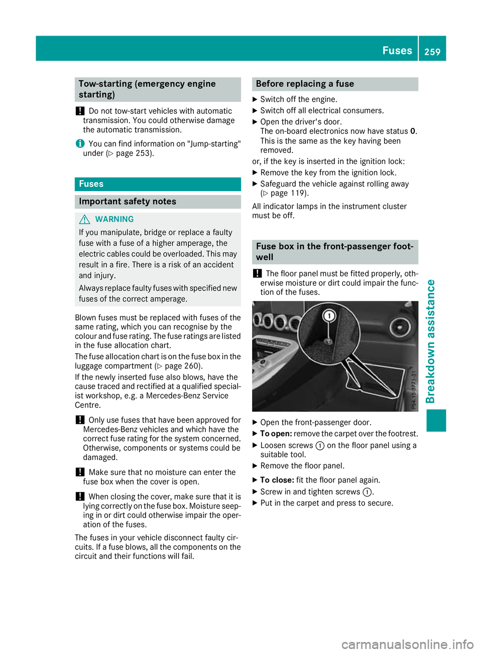
erwise moisture or dirt could impair the func- tion of the fuses. X
Open the front-passenger door.
X To open: remove the carpet over the footrest.
X Loosen screws :on the floor panel using a
suitable tool.
X Remove the floor panel.
X To close: fit the floor panel again.
X Screw in and tighten screws :.
X Put in the carpet and press to secure. Fuses
259Breakdown assistance Z
Page 275 of 289
Lowering the vehicle
G
WARNING
The wheels could work loose if the wheel nuts and bolts are not tightened to the specified
tightening torque. There is a risk of accident.
Have the tightening torque immediately
checked at a qualified specialist workshop
after a wheel is changed.
! Vehicles with a collapsible emergency
spare wheel: Inflate the collapsible emer-
gency spare wheel using the tyre inflation
compressor before lowering the vehicle. The
rim could otherwise be damaged.
X Turn the crank of the jack anti-clockwise until
the vehicle is once again standing firmly on
the ground.
X Place the jack to one side. X
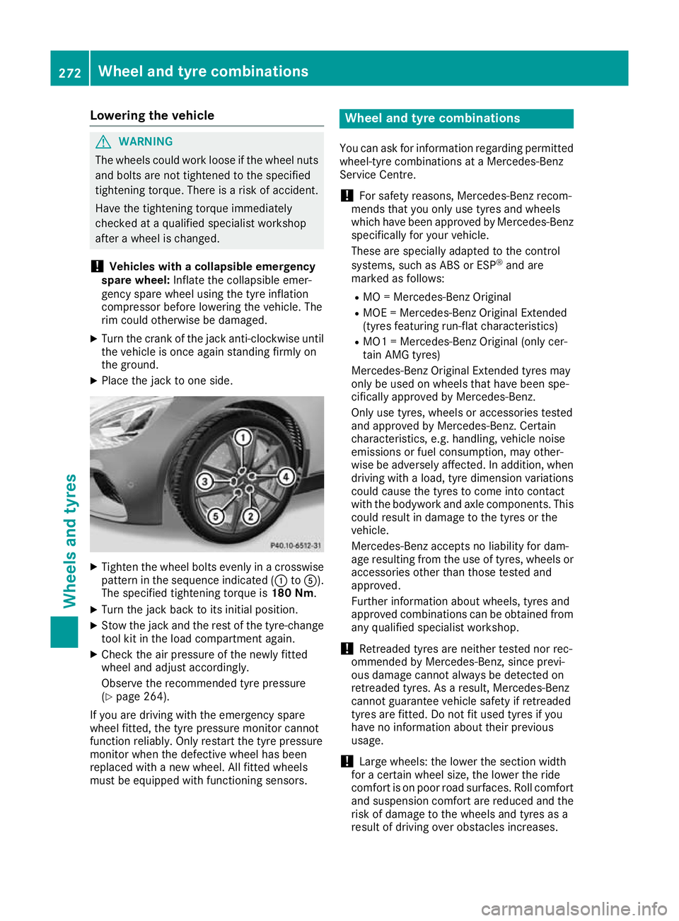
Tighten the wheel bolts evenly in a crosswise
pattern in the sequence indicated (: toA).
The specified tightening torque is 180 Nm.
X Turn the jack back to its initial position.
X Stow the jack and the rest of the tyre-change
tool kit in the load compartment again.
X Check the air pressure of the newly fitted
wheel and adjust accordingly.
Observe the recommended tyre pressure
(Y page 264).
If you are driving with the emergency spare
wheel fitted, the tyre pressure monitor cannot
function reliably. Only restart the tyre pressure
monitor when the defective wheel has been
replaced with a new wheel. All fitted wheels
must be equipped with functioning sensors. Wheel and tyre combinations
You can ask for information regarding permitted
wheel-tyre combinations at a Mercedes-Benz
Service Centre.
! For safety reasons, Mercedes-Benz recom-
mends that you only use tyres and wheels
which have been approved by Mercedes-Benz specifically for your vehicle.
These are specially adapted to the control
systems, such as ABS or ESP ®
and are
marked as follows:
R MO = Mercedes-Benz Original
R MOE = Mercedes-Benz Original Extended
(tyres featuring run-flat characteristics)
R MO1 = Mercedes-Benz Original (only cer-
tain AMG tyres)
Mercedes-Benz Original Extended tyres may
only be used on wheels that have been spe-
cifically approved by Mercedes-Benz.
Only use tyres, wheels or accessories tested
and approved by Mercedes-Benz. Certain
characteristics, e.g. handling, vehicle noise
emissions or fuel consumption, may other-
wise be adversely affected. In addition, when
driving with a load, tyre dimension variations
could cause the tyres to come into contact
with the bodywork and axle components. This
could result in damage to the tyres or the
vehicle.
Mercedes-Benz accepts no liability for dam-
age resulting from the use of tyres, wheels or accessories other than those tested and
approved.
Further information about wheels, tyres and
approved combinations can be obtained from
any qualified specialist workshop.
! Retreaded tyres are neither tested nor rec-
ommended by Mercedes-Benz, since previ-
ous damage cannot always be detected on
retreaded tyres. As a result, Mercedes-Benz
cannot guarantee vehicle safety if retreaded
tyres are fitted. Do not fit used tyres if you
have no information about their previous
usage.
! Large wheels: the lower the section width
for a certain wheel size, the lower the ride
comfort is on poor road surfaces. Roll comfort and suspension comfort are reduced and therisk of damage to the wheels and tyres as a
result of driving over obstacles increases. 272
Wheel and tyre combinationsWheels and tyres