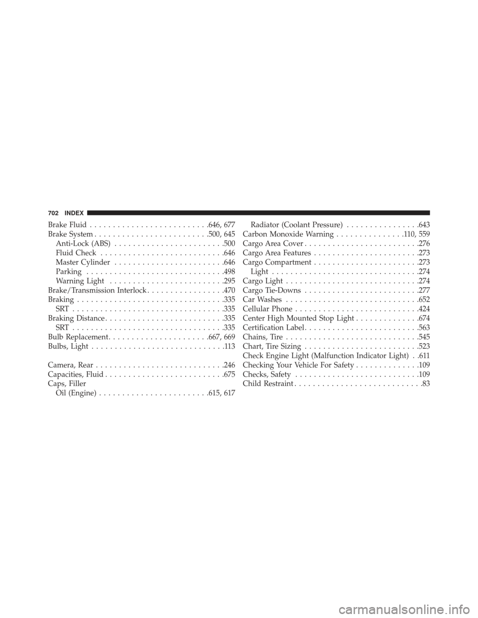
Brake Fluid......................... .646, 677
Brake System ........................ .500, 645
Anti-Lock (ABS) ....................... .500
Fluid Check .......................... .646
Master Cylinder ....................... .646
Parking ............................. .498
Warning Light ........................ .295
Brake/Transmission Interlock .................470
Braking ............................... .335
SRT ................................ .335
Braking Distance ......................... .335
SRT ................................ .335
Bulb Replacement ..................... .667, 669
Bulbs, Light .............................113
Camera, Rear ........................... .246
Capacities, Fluid ......................... .675
Caps, Filler Oil (Engine) ....................... .615, 617Radiator (Coolant Pressure)
................643
Carbon Monoxide Warning ...............110,559
Cargo Area Cover ........................ .276
Cargo Area Features ...................... .273
Cargo Compartment ...................... .273
Light ............................... .274
Cargo Light ............................ .274
Cargo Tie-Downs ........................ .277
Car Washes ............................ .652
Cellular Phone .......................... .424
Center High Mounted Stop Light ..............674
Certification Label ........................ .563
Chains, Tire ............................ .545
Chart, Tire Sizing ........................ .523
Check Engine Light (Malfunction Indicator Light) . .611
Checking Your Vehicle For Safety ..............109
Checks, Safety .......................... .109
Child Restraint ............................83
702 INDEX
INSTALLATION OF RADIO TRANSMITTING
EQUIPMENTSpecial design considerations are incorporated into this
vehicle’s electronic system to provide immunity to radio
frequency signals. Mobile two-way radios and telephone
equipment must be installed properly by trained person-
nel. The following must be observed during installation.
The positive power connection should be made directly
to the battery and fused as close to the battery as possible.
The negative power connection should be made to body
sheet metal adjacent to the negative battery connection.
This connection should not be fused.
Antennas for two-way radios should be mounted on the
roof or the rear area of the vehicle. Care should be used
in mounting antennas with magnet bases. Magnets may
affect the accuracy or operation of the compass on
vehicles so equipped.The antenna cable should be as short as practical and
routed away from the vehicle wiring when possible. Use
only fully shielded coaxial cable.
Carefully match the antenna and cable to the radio to
ensure a low Standing Wave Ratio (SWR).
Mobile radio equipment with output power greater than
normal may require special precautions.
All installations should be checked for possible interfer-
ence between the communications equipment and the
vehicle’s electronic systems.