Page 57 of 117

WARNING!
Improper towing can lead to a collision. Follow these
guidelines to make your trailer towing as safe as
possible:
•Make certain that the load is secured in the trailer
and will not shift during travel. When trailering
cargo that is not fully secured, dynamic load shifts
can occur that may be difficult for the driver to
control. You could lose control of your vehicle and
have a collision.
• When hauling cargo or towing a trailer, do not
overload your vehicle or trailer. Overloading can
cause a loss of control, poor performance or dam-
age to brakes, axle, engine, transmission, steering,
suspension, chassis structure or tires.
• Safety chains must always be used between your
vehicle and trailer. Always connect the chains to
(Continued)
WARNING! (Continued)
the hook retainers of the vehicle hitch. Cross the
chains under the trailer tongue and allow enough
slack for turning corners.
• Vehicles with trailers should not be parked on a
grade. When parking, apply the parking brake on
the tow vehicle. Put the tow vehicle transmission in
PARK. For four-wheel drive vehicles, make sure
the transfer case is not in NEUTRAL. Always,
block or �chock�the trailer wheels.
• GCWR must not be exceeded.
• Total weight must be distributed between the tow
vehicle and the trailer such that the following four
ratings are not exceeded:
1. GVWR
2. GTW
(Continued)
4
STARTING AND OPERATING 55
Page 58 of 117

3. GAWR
4.
Tongue weight rating for the trailer hitch utilized.
Towing Requirements — Tires
•Do not attempt to tow a trailer while using a compact
spare tire.
• Proper tire i")
WARNING!(Continued)
3. GAWR
4.
Tongue weight rating for the trailer hitch utilized.
Towing Requirements — Tires
•Do not attempt to tow a trailer while using a compact
spare tire.
• Proper tire inflation pressures are essential to the safe
and satisfactory operation of your vehicle. Refer to
“Tires – General Information” in “Starting And Oper-
ating” for proper tire inflation procedures.
• Check the trailer tires for proper tire inflation pres-
sures before trailer usage. •
Check for signs of tire wear or visible tire damage before
towing a trailer. Refer to “Tires – General Information”
in “Starting And Operating” for the proper inspection
procedure.
• When replacing tires, refer to “Tires – General Infor-
mation” in “Starting And Operating” for the proper
tire replacement procedures. Replacing tires with a
higher load carrying capacity will not increase the
vehicle’s GVWR and GAWR limits.
Towing Requirements — Trailer Brakes
WARNING!
• Do not connect trailer brakes to your vehicle’s
hydraulic brake lines. It can overload your brake
system and cause it to fail. You might not have
brakes when you need them and could have an
accident.
(Continued)
56 STARTING AND OPERATING
Page 59 of 117

•Towing any trailer will increase your stopping
distance. When towing you should allow for addi-
tional space between your vehicle and the vehicle
in front of you. Failure to do")
WARNING!(Continued)
•Towing any trailer will increase your stopping
distance. When towing you should allow for addi-
tional space between your vehicle and the vehicle
in front of you. Failure to do so could result in an
accident.
CAUTION!
If the trailer weighs more than 1,000 lbs (453 kg)
loaded, it should have its own brakes and they
should be of adequate capacity. Failure to do this
could lead to accelerated brake lining wear, higher
brake pedal effort, and longer stopping distances.
• Do not interconnect the hydraulic brake system or
vacuum system of your vehicle with that of the trailer.
This could cause inadequate braking and possible
personal injury. •
An electronically actuated trailer brake controller is
required when towing a trailer with electronically
actuated brakes. When towing a trailer equipped with
a hydraulic surge actuated brake system, an electronic
brake controller is not required.
• Trailer brakes are recommended for trailers over
1,000 lbs (453 kg) and required for trailers in excess of
1,653 lbs (749 kg).Towing Requirements — Trailer Lights And Wiring
Whenever you pull a trailer, regardless of the trailer size,
stoplights and turn signals on the trailer are required for
motoring safety.
The Trailer Tow Package may include a four- and seven-
pin wiring harness. Use a factory approved trailer har-
ness and connector.
NOTE: Do not cut or splice wiring into the vehicles
wiring harness.
4
STARTING AND OPERATING 57
Page 60 of 117
The electrical connections are all complete to the vehicle
but you must mate the harness to a trailer connector.
Refer to the following illustrations.
Four-Pin Connector
1 — Female Pins
2 — Male Pin
3 — Ground4 — Park
5 — Left Stop/Turn
6 — Right Stop/Turn
Seven-Pin Connector
1 — Battery
2 — Backup Lamps
3 — Right Stop/Turn
4 — Electric Brakes5 — Ground
6 — Left Stop/Turn
7 — Running Lamps
58 STARTING AND OPERATING
Page 61 of 117

Towing Tips
Before setting out on a trip, practice turning, stopping
and backing the trailer up in an area away from heavy
traffic.
Automatic Transmission
The DRIVE range can be selected when towing. The
transmission controls include a drive strategy to avoid
frequent shifting when towing. However, if frequent
shifting does occur while in DRIVE, you can use the
Paddle Shift switches or manual gate of shifter to manu-
ally select a lower gear.
NOTE:Using a lower gear while operating the vehicle
under heavy loading conditions, will improve perfor-
mance and extend transmission life by reducing exces-
sive shifting and heat buildup. This action will also
provide better engine braking.
Paddle Shift Mode
• When using the Paddle Shift switches, select the
highest gear that allows for adequate performance and
avoids frequent downshifts. For example, choose “5” if
the desired speed can be maintained. Choose “4” or
“3” if needed to maintain the desired speed.
• To prevent excess heat generation, avoid continuous
driving at high RPM. Reduce vehicle speed as neces-
sary to avoid extended driving at high RPM. Return to
a higher gear or vehicle speed when grade and road
conditions allow.
Electronic Speed Control — If Equipped
• Do not use in hilly terrain or with heavy loads.
• When using the speed control, if you experience speed
drops greater than 10 mph (16 km/h), disengage until
you can get back to cruising speed.
• Use speed control in flat terrain and with light loads to
maximize fuel efficiency.
4
STARTING AND OPERATING 59
Page 62 of 117

Cooling System
To reduce potential for engine and transmission over-
heating, take the following actions:
City Driving
When stopped for short periods of time, shift the trans-
mission into NEUTRAL and increase engine idle speed.
Highway Driving
Reduce speed.
Air Conditioning
Turn off temporarily.
DIESEL EXHAUST FLUID
Your vehicle is equipped with a Selective Catalytic Re-
duction system to meet the very stringent diesel emis-
sions standards required by the Environmental Protec-
tion Agency.
The purpose of the SCR system is to reduce levels of NOx
(oxides of nitrogen emitted from engines) that are harm-
ful to our health and the environment to a near-zero level.
Small quantities of Diesel Exhaust Fluid (DEF) is injected
into the exhaust upstream of a catalyst where, when
vaporized, it converts smog-forming nitrogen oxides
(NOx) into harmless nitrogen (N2) and water vapor
(H2O), two natural components of the air we breathe.
You can operate with the comfort that your vehicle is
contributing to a cleaner, healthier world environment
for this and generations to come.
60 STARTING AND OPERATING
Page 63 of 117
 injection system and a Selective Catalytic Reduc-
tion (SCR) catalyst to meet the emission requirements.
The DEF injection sy")
System Overview
This vehicle is equipped with a Diesel Exhaust Fluid
(DEF) injection system and a Selective Catalytic Reduc-
tion (SCR) catalyst to meet the emission requirements.
The DEF injection system consists of the following com-
ponents:
•DEF tank
• DEF pump
• DEF injector
• Electronically-heated DEF lines
• NOx sensors
• Temperature sensors
• SCR catalyst
The DEF injection system and SCR catalyst enable the
achievement of diesel emissions requirements; while main-
taining outstanding fuel economy, drivability, torque and
power ratings.
Refer to “Driver Information Display (DID)” in “Under-
standing Your Instrument Panel” for system messages
and warnings.
NOTE:
•
Your vehicle is equipped with a DEF injection system.
You may occasionally hear an audible clicking noise
from under the vehicle at a stop. This is normal opera-
tion.
• The DEF pump will run for a period of time after
engine shutdown to purge the DEF system. This is
normal operation and may be audible from the rear of
the vehicle.
4
STARTING AND OPERATING 61
Page 64 of 117
ADDING FUEL
1. Press the fuel filler door release switch (located underthe headlamp switch).
2. Open the fuel filler door.
1 — Fuel Fill Location
2 — Diesel Exhaust Fluid Fill Location
NOTE: There is no fuel filler cap. A flapper door inside
the filler pipe seals the system.
Fuel Filler Door Release Switch
Fuel and Diesel Exhaust Fluid Fill Location
62 STARTING AND OPERATING
 1
1 2
2 3
3 4
4 5
5 6
6 7
7 8
8 9
9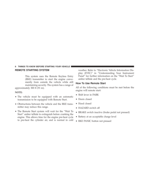 10
10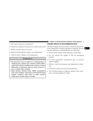 11
11 12
12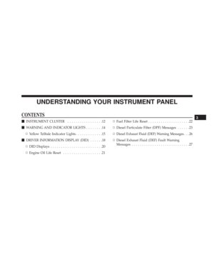 13
13 14
14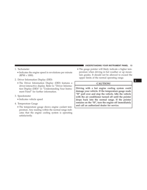 15
15 16
16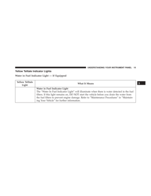 17
17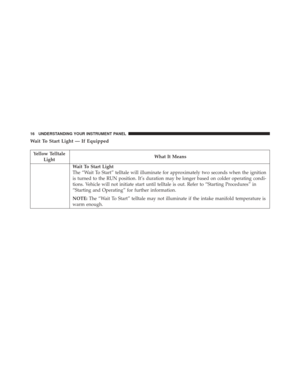 18
18 19
19 20
20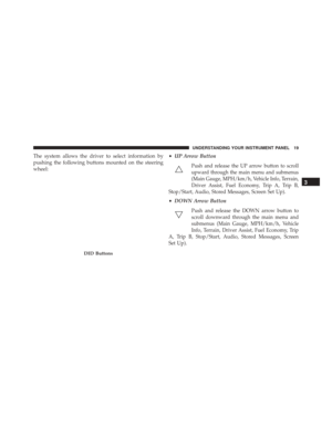 21
21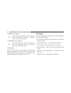 22
22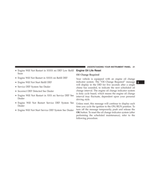 23
23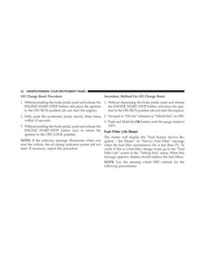 24
24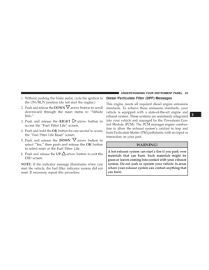 25
25 26
26 27
27 28
28 29
29 30
30 31
31 32
32 33
33 34
34 35
35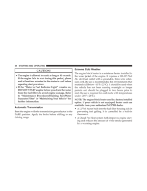 36
36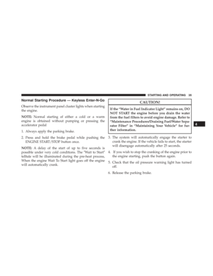 37
37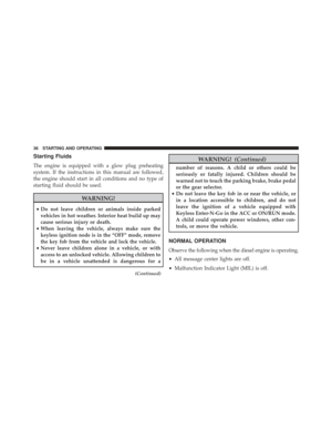 38
38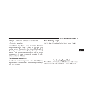 39
39 40
40 41
41 42
42 43
43 44
44 45
45 46
46 47
47 48
48 49
49 50
50 51
51 52
52 53
53 54
54 55
55 56
56 57
57 58
58 59
59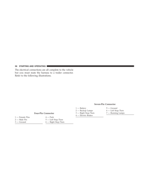 60
60 61
61 62
62 63
63 64
64 65
65 66
66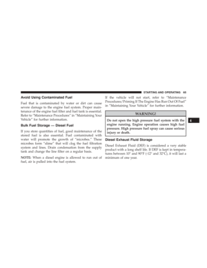 67
67 68
68 69
69 70
70 71
71 72
72 73
73 74
74 75
75 76
76 77
77 78
78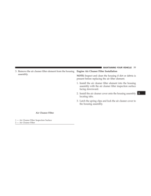 79
79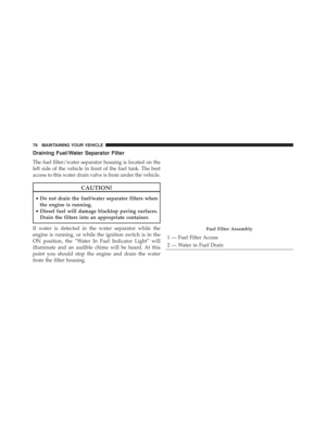 80
80 81
81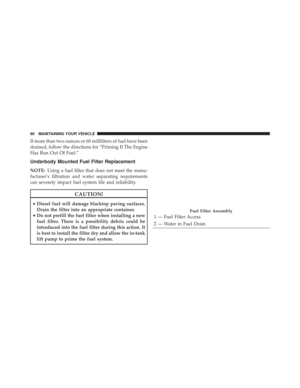 82
82 83
83 84
84 85
85 86
86 87
87 88
88 89
89 90
90 91
91 92
92 93
93 94
94 95
95 96
96 97
97 98
98 99
99 100
100 101
101 102
102 103
103 104
104 105
105 106
106 107
107 108
108 109
109 110
110 111
111 112
112 113
113 114
114 115
115 116
116
.
2. Open the fuel filler door.
1 — Fuel Fill Location
2 — Diesel Exhaust Fluid Fill Location
NOTE: There")