2016 HYUNDAI IX35 ABS
[x] Cancel search: ABSPage 418 of 550
Driving your vehicle70
5Parking on hills Generally, if you have a trailer attached to
your vehicle, you should not park your
vehicle on a hill. People can be seriously
or fatally injured, and both your vehicle
and the trailer can be damaged if unex-
pectedly roll down hill. However, if you ever have to park your
trailer on a hill, here's how to do it:
1. Pull the vehicle into the parking space.
Turn the steering wheel in the direction
of the kerb (left if headed down hill,
right if headed up hill).
2. If the vehicle has a manual transaxle, place the car in neutral. If the vehicle
has an automatic transaxle, place the
car in P (Park).
3. Set the parking brake and shut off the vehicle.
4. Place chocks under the trailer wheels on the down hill side of the wheels.
5. Start the vehicle, hold the brakes, shift to neutral, release the parking brake
and slowly release the brakes until the
trailer chocks absorb the load.
6. Reapply the brakes, reapply the park- ing brake and shift the vehicle to R
(Reverse) for manual transaxle or P
(Park) for automatic transaxle.
7. Shut off the vehicle and release the vehicle brakes but leave the parking
brake set.
WARNING
- Parking on ahill
Parking your vehicle on a hill with a
trailer attached could cause seri-
ous injury or death, should the trail-
er break loose.
WARNING
- Parking brake
It can be dangerous to get out of
your vehicle if the parking brake is
not firmly set.
If you have left the engine running,
the vehicle can move suddenly. You
or others could be seriously or
fatally injured.
EL(FL) UK 5.QXP 12/16/2014 8:10 PM Page 70
Page 428 of 550
What to do in an emergency66Jump starting procedure
1. Make sure the booster battery is 12-voltand that its negative terminal is grounded.
2. If the booster battery is in another vehicle, do not allow the vehicles to touch.
3. Turn off all unnecessary electrical loads.4. Connect the jumper cables in the exact sequence shown in the illustration. First
connect one end of a jumper cable to
the positive terminal of the discharged
battery (1), then connect the other end
to the positive terminal on the booster
battery (2). Proceed to connect one end
of the other jumper cable to the negative
terminal of the booster battery (3), then
the other end to a solid, stationary,
metallic point (for example, the engine
lifting bracket) away from the battery (4).
Do not connect it to or near any part that
moves when the engine is cranked.
Do not allow the jumper cables to con-
tact anything except the correct battery
terminals or the correct ground. Do not
lean over the battery when making con-
nections. 5. Start the engine of the vehicle with the
booster battery and let it run at 2,000
rpm, then start the engine of the vehi-
cle with the discharged battery.
If the cause of your battery discharging isnot apparent, we recommend that the system be checked by a HYUNDAIauthorised repairer.Push-starting Your manual transaxle-equipped vehicle
should not be push-started because it
might damage the emission control sys-
tem.
Vehicles equipped with automatic
transaxle cannot be push-started.
Follow the directions in this section for
jump-starting.
WARNING
Never tow a vehicle to start it
because the sudden surge forward
when the engine starts could cause
a collision with the tow vehicle.
CAUTION
- Battery cables
Do not connect the jumper cablefrom the negative terminal of thebooster battery to the negative ter-minal of the discharged battery.This can cause the discharged bat-tery to overheat and crack, releas-ing battery acid.
CAUTION
-AGM battery
(if equipped)
AAbsorbent Glass Matt (AGM)
batteries are maintenance-freeand we recommend that the sys-tem be serviced by a HYUNDAIauthorised repairer. For chargingyour AGM battery, use only fully automatic battery chargers thatare specially developed for AGM batteries.
When replacing the AGM battery, we recommend that you use partsfor replacement from a HYUNDAIauthorised repairer.
Do not open or remove the cap on top of the battery. This may causeleaks of internal electrolyte thatcould result in severe injury.
If the AGM battery is reconnected or replaced, ISG function will notoperate immediately.
If you want to use the ISG func-tion, the battery sensor needs to be calibrated for approximately 4hours with the ignition off.
EL(FL) UK 6.QXP 12/16/2014 8:12 PM Page 6
Page 444 of 550
What to do in an emergency22
67. Place the jack at the front or rear
jacking position closest to the tyre
you are changing. Place the jack
at the designated locations under
the frame. The jacking positions
are plates welded to the frame
with two tabs and a raised dot to
index with the jack. 8. Insert the jack handle into the jack
and turn it clockwise, raising the
vehicle until the tyre just clears the
ground. This measurement is
approximately 1.2 in (30 mm).
Before removing the wheel lug
nuts, make sure the vehicle is sta-
ble and that there is no chance for
movement or slippage. 9. Loosen the wheel nuts and
remove them with your fingers.
Slide the wheel off the studs and
lay it flat so it cannot roll away. To
put the wheel on the hub, pick up
the spare tyre, line up the holes
with the studs and slide the wheel
onto them. If this is difficult, tip the
wheel slightly and get the top hole
in the wheel lined up with the top
stud. Then jiggle the wheel back
and forth until the wheel can be
slid over the other studs.
WARNING
- Jack location
To reduce the possibility of
injury, be sure to use only the
jack provided with the vehicle
and in the correct jack position;
never use any other part of the
vehicle for jack support.
OCM049013N
OCM054012
EL(FL) UK 6.QXP 12/16/2014 8:12 PM Page 22
Page 498 of 550
Maintenance38
7
Compact spare tyre replacement
(if equipped)A compact spare tyre has a shorter
tread life than a regular size tyre.
Replace it when you can see the
tread wear indicator bars on the tyre.
The replacement compact spare tyre
should be the same size and design
tyre as the one provided with your
new vehicle and should be mounted
on the same compact spare tyre
wheel. The compact spare tyre is not
designed to be mounted on a regular
size wheel, and the compact spare
tyre wheel is not designed for mount-
ing a regular size tyre.
(Continued)
The use of any other tyre size or type may seriously affect
ride, handling, ground clear-
ance, stopping distance, body
to tyre clearance, snow tyre
clearance, and speedometer
reliability.
It is best to replace all four tyres at the same time. If that
is not possible, or necessary,
then replace the two front or
two rear tyres as a pair.
Replacing just one tyre can
seriously affect your vehicle’s
handling.
The ABS works by comparing the speed of the wheels. Tyre
size can affect wheel speed.
When replacing tyres, all 4
tyres must use the same size
originally supplied with the
vehicle. Using tyres of a dif-
ferent size can cause the ABS
(Anti-lock Brake System)
and ESC (Electronic Stability
Control) (if equipped) to work
irregularly.
WARNING
- Replacingtyres
Driving on worn-out tyres is very hazardous and will
reduce braking effectiveness,
steering accuracy, and trac-
tion.
Your vehicle is equipped with tyres designed to provide for
safe ride and handling capa-
bility. Do not use a size and
type of tyre and wheel that is
different from the one that is
originally installed on your
vehicle. It can affect the safety
and performance of your vehi-
cle, which could lead to han-
dling failure or rollover and
serious injury. When replacing
the tyres, be sure to equip all
four tyres with the tyre and
wheel of the same size, type,
tread, brand and load-carrying
capacity.
(Continued)
EL(FL) UK 7.QXP 3/4/2015 9:05 PM Page 38
Page 513 of 550
753
Maintenance
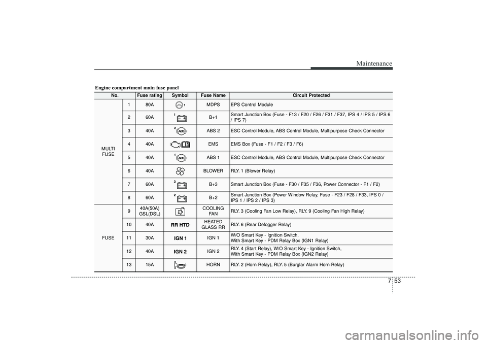
Engine compartment main fuse panel
No.
Fuse rating
Symbol
Fuse Name
Circuit Protected
MULTIFUSE
1
80A
MDPS
EPS Control Module
2
60A
B+1
Smart Junction Box (Fuse - F13 / F20 / F26 / F31 / F37, IPS 4 / IPS 5 / IPS 6
/ IPS 7)
3
40A
ABS 2
ESC Control Module, ABS Control Module, Multipurpose Check Connector
4
40A
EMS
EMS Box (Fuse - F1 / F2 / F3 / F6)
5
40A
ABS 1
ESC Control Module, ABS Control Module, Multipurpose Check Connector
6
40A
BLOWER
RLY. 1 (Blower Relay)
7
60A
B+3
Smart Junction Box (Fuse - F30 / F35 / F36, Power Connector - F1 / F2)
8
60A
B+2
Smart Junction Box (Power Window Relay, Fuse - F23 / F28 / F33, IPS 0 /
IPS 1 / IPS 2 / IPS 3)
FUSE
9
40A(50A)
GSL(DSL)
COOLING FA N
RLY. 3 (Cooling Fan Low Relay), RLY. 9 (Cooling Fan High Relay)
10
40A
HEATED
GLASS RR
RLY. 6 (Rear Defogger Relay)
11
30A
IGN 1
W/O Smart Key - Ignition Switch,
With Smart Key - PDM Relay Box (IGN1 Relay)
12
40A
IGN 2
RLY. 4 (Start Relay), W/O Smart Key - Ignition Switch,
With Smart Key - PDM Relay Box (IGN2 Relay)
13
15A
HORN
RLY. 2 (Horn Relay), RLY. 5 (Burglar Alarm Horn Relay)
EL(FL) UK 7.QXP 3/4/2015 9:07 PM Page 53
Page 514 of 550
Maintenance54
7
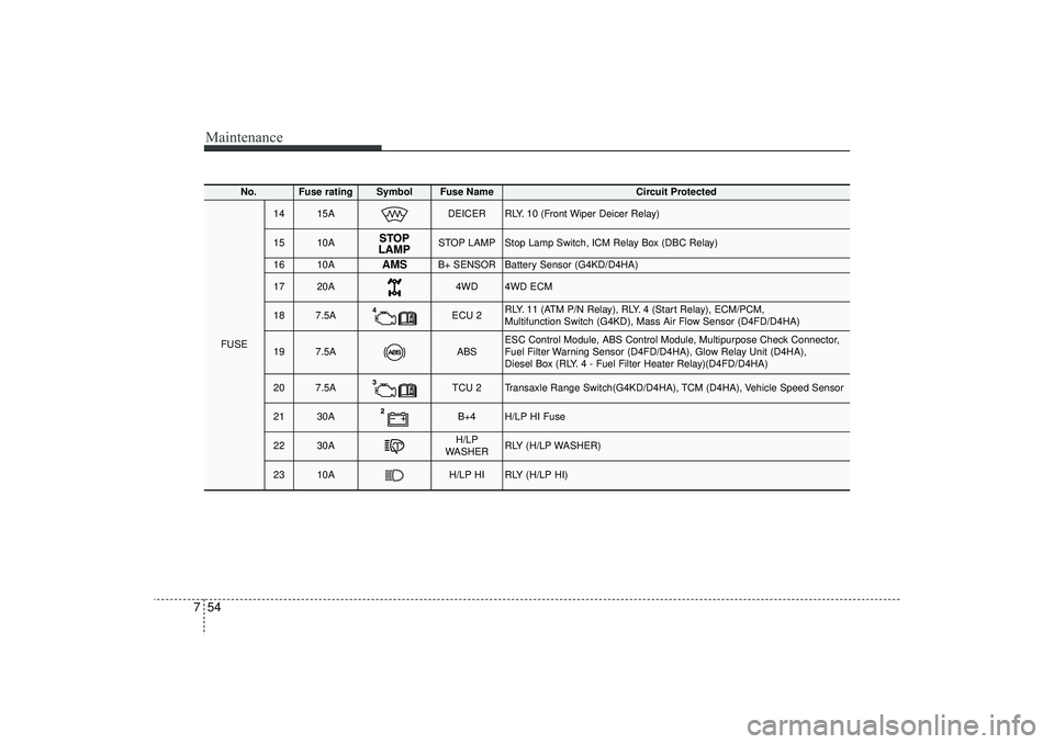
No.
Fuse rating
Symbol
Fuse Name
Circuit Protected
FUSE
14
15A
DEICER
RLY. 10 (Front Wiper Deicer Relay)
15
10A
STOP LAMP
Stop Lamp Switch, ICM Relay Box (DBC Relay)
16
10A
AMS
B+ SENSOR
Battery Sensor (G4KD/D4HA)
17
20A
4WD
4WD ECM
18
7.5A
ECU 2
RLY. 11 (ATM P/N Relay), RLY. 4 (Start Relay), ECM/PCM,
Multifunction Switch (G4KD), Mass Air Flow Sensor (D4FD/D4HA)
19
7.5A
ABS
ESC Control Module, ABS Control Module, Multipurpose Check Connector,
Fuel Filter Warning Sensor (D4FD/D4HA), Glow Relay Unit (D4HA),
Diesel Box (RLY. 4 - Fuel Filter Heater Relay)(D4FD/D4HA)
20
7.5A
TCU 2
Transaxle Range Switch(G4KD/D4HA), TCM (D4HA), Vehicle Speed Sensor
21
30A
B+4
H/LP HI Fuse
22
30A
H/LP
WASHER
RLY (H/LP WASHER)
23
10A
H/LP HI
RLY (H/LP HI)
EL(FL) UK 7.QXP 3/4/2015 9:07 PM Page 54
Page 519 of 550

759
Maintenance
Turn signal light/Position lightTurn signal light
1. Turn off the engine and open the bon-net.
2. Remove the socket from the assembly by turning the socket counterclockwise
until the tabs on the socket align with
the slots on the assembly.
3. Remove the bulb from the socket by pressing it in and rotating it counter-
clockwise until the tabs on the bulb
align with the slots in the socket. Pull
the bulb out of the socket.
4. Insert a new bulb by inserting it into the socket and rotating it until it locks
into place.
5. Install the socket in the assembly by aligning the tabs on the socket with the
slots in the assembly. Push the socket
into the assembly and turn the socket
clockwise.
Position light
If the light bulb does not operate, we rec-
ommend that the system be checked by
a HYUNDAI authorised repairer.
(Continued)
If a bulb becomes damaged or cracked, replace it immediately
and carefully dispose of it.
Wear eye protection when chang- ing a bulb. Allow the bulb to cool
down before handling it.
WARNING
- Halogen bulbs
Halogen bulbs contain pressur-ized gas that will produce flying
pieces of glass if broken.
Always handle them carefully, and avoid scratches and abra-
sions. If the bulbs are lit, avoid
contact with liquids. Never touch
the glass with bare hands.
Residual oil may cause the bulb
to overheat and burst when lit. A
bulb should be operated only
when installed in a headlight.
(Continued)
OHD076046
EL(FL) UK 7.QXP 3/4/2015 9:07 PM Page 59
Page 520 of 550

Maintenance60
7Front fog light bulbs (if equipped)1. Remove the front bumper under cover.
2. Reach your hand into the back of the
front bumper.
3. Disconnect the power connector from the socket.
4. Remove the bulb-socket from the housing by turning the socket counter
clockwise until the tabs on the socket
align with the slots on the housing.
5. Install the new bulb-socket into the housing by aligning the tabs on the
socket with the slots in the housing.
Push the socket into the housing and
turn the socket clockwise.
6. Connect the power connector to the socket.
7. Reinstall the front bumper under cover.
Headlight and front fog light aim-
ing (for Europe)Headlight aiming1. Inflate the tyres to the specified pres- sure and remove any loads from the
vehicle except the driver, spare tyre,
and tools.
2. The vehicle should be placed on a flat floor.
3. Draw vertical lines (Vertical lines pass- ing through respective head lamp cen-
tres) and a horizontal line (Horizontal
line passing through centre of head
lamps) on the screen. 4. With the head lamp and battery in nor-
mal condition, aim the head lamps so
the brightest portion falls on the hori-
zontal and vertical lines.
5. To aim the low/high beam left or right, turn the driver (2) clockwise or coun-
terclockwise. To aim the low/high beam
up or down, turn the driver (1) clock-
wise or counterclockwise.
OEL073257
EL(FL) UK 7.QXP 3/4/2015 9:07 PM Page 60