Page 57 of 80
*
Can alert you when a potential frontal collision with a vehicle or pedes\
trian is
det")
106 ||‚Äā‚Äā‚Äā‚Äā107
DRIVING
DRIVING
*if‚Äāequipped
Collision Mitigation Braking System‚ĄĘ (CMBS‚ĄĘ)*
Can alert you when a potential frontal collision with a vehicle or pedes\
trian is
determined‚Äāand‚Äāreduce‚Äāyour‚Äāvehicle‚Äāspeed‚Äāwhen‚Äāa‚Äācollision‚Äāis‚Äādeemed‚Äāunavoidable‚Äā
to‚Äāhelp‚Äāminimize‚Äācollision‚Äāseverity.
The‚Äāsystem‚Äāprovides‚Äāvisual‚Äāand‚Äāaudible‚Äāalerts‚Äāif‚Äāyou‚Äā
do not take appropriate action to avoid a collision.
Alert Stages
The‚Äāsystem‚Äāhas‚Äāthree‚Äāalert‚Äāstages‚Äāfor‚Äāa‚Äāpossible‚Äā
collision.‚ÄāDepending‚Äāon‚Äāthe‚Äācircumstances‚Äāor‚Äā
CMBS settings, CMBS may not go through all of
the‚Äāstages‚Äābefore‚Äāinitiating‚Äāthe‚Äālast‚Äāstage.
Stage 1:‚Äā‚ÄāVisual‚Äāwarnings‚Äāand‚Äāaudible‚Äāwarning
Stage 2:‚Äā‚ÄāVisual‚Äāwarnings,‚Äāaudible‚Äāwarning,‚Äāand‚Äālight‚Äābrake‚Äāapplication
Stage 3:‚Äā‚ÄāVisual‚Äāwarnings,‚Äāaudible‚Äāwarning,‚Äāand‚Äāstrong‚Äābrake‚Äāapplication
Beep
LaneWatch‚ĄĘ*
Check the passenger-side rear areas in the upper display when the right turn signal
is activated.
LaneWatch display
Activating LaneWatch
Activate the right turn signal. The LaneWatch
display‚Äāappears.‚ÄāCheck‚Äāthe‚Äādisplay‚Äāfor‚Äāblind‚Äāspots,‚Äā
and visually confirm that it is safe to change lanes.
You‚Äācan‚Äāalso‚Äāpress‚Äāthe‚ÄāLaneWatch‚Äābutton‚Äāon‚Äāthe‚Äā
end of the turn signal switch to view a constant
real-time display. Press it again to turn the display
off.
*if‚Äāequipped
Turning CMBS On or Off
Press‚Äāand‚Äāhold‚Äāthe‚ÄāCMBS‚ÄāOFF‚Äābutton.‚ÄāA‚Äābeep‚Äāsounds‚Äā
and‚Äāa‚Äāmessage‚Äāappears‚Äāin‚Äāthe‚ÄāMID.‚ÄāThe‚ÄāCMBS‚Äā
indicator appears when the system is off.
Changing Settings
Change‚Äāthe‚Äāalert‚Äādistance.‚ÄāUse‚Äāthe‚Äāsteering‚Äāwheel‚Äābuttons‚Äāto‚Äāmake‚Äāand‚Äāenter‚Äā
selections‚Äāin‚Äāthe‚ÄāMID‚Äā(see‚Äāpage‚Äā30).
1. Select‚Äāthe‚ÄāCustomize‚ÄāSettings‚Äādisplay.
2. Select Change Settings.
3. Select‚ÄāDriver‚ÄāAssist‚ÄāSystem‚ÄāSetup.
4.‚ÄāSelect‚ÄāForward‚ÄāCollision‚ÄāWarning‚ÄāDistance.‚ÄāSelect‚ÄāLong,‚ÄāNormal,‚Äāor‚ÄāShort.
5. Exit‚Äāthe‚Äāmenu.
Important Safety Reminder
CMBS‚Äāis‚Äādesigned‚Äāto‚Äāreduce‚Äāthe‚Äāseverity‚Äāof‚Äāan‚Äāunavoidable‚Äācollision.‚ÄāIt‚Äādoes‚Äānot‚Äā
prevent‚Äācollision‚Äānor‚Äāstop‚Äāthe‚Äāvehicle‚Äāautomatically.‚ÄāIt‚Äāis‚Äāstill‚Äāyour‚Äāresponsibility‚Äāto‚Äā
operate‚Äāthe‚Äābrake‚Äāpedal‚Äāand‚Äāsteering‚Äāwheel‚Äāappropriately‚Äāaccording‚Äāto‚Äāthe‚Äādriving‚Äā
conditions.
Failure‚Äāto‚Äāvisually‚Äāconfirm‚Äāthat‚Äāit‚Äāis‚Äāsafe‚Äāto‚Äāchange‚Äālanes‚Äābefore‚Äādoing‚Äāso‚Äāmay‚Äā
result in a crash and serious injury or death.
Do‚Äānot‚Äārely‚Äāonly‚Äāon‚ÄāLaneWatch‚Äāwhile‚Äādriving.‚ÄāAlways‚Äālook‚Äāin‚Äāyour‚Äāmirrors,‚Äāto‚Äā
either‚Äāside‚Äāof‚Äāyour‚Äāvehicle,‚Äāand‚Äābehind‚Äāyou‚Äāfor‚Äāother‚Äāvehicles‚Äābefore‚Äāchanging‚Äā
lanes.
WARNING
Changing Settings
Customize‚Äāthe‚Äādisplay‚Äāand‚Äāhow‚Äāand‚Äāwhen‚Äāthe‚Äādisplay‚Äāappears.
1. From‚Äāthe‚ÄāHOME‚Äāscreen,‚Äāselect‚ÄāSettings.
2. Select Camera.
3. Select LaneWatch.
4.‚ÄāSelect an option and make the preferred changes.
5. Press‚Äāthe‚ÄāBACK‚Äābutton‚Äāto‚Äāexit‚Äāthe‚Äāmenu.
Important Safety Reminder
Like all assistance systems, LaneWatch has limitations. Over-reliance on the system
may result in a collision.
Page 58 of 80
,‚Äāa‚Äāreal-time‚Äāimage‚Äāof‚Äāthe‚Äāarea‚Äābehind‚Äāyour‚Äāvehicle‚Äāis‚Äā
shown‚Äāin‚Äāthe‚Ä")
108 || 109
DRIVING
DRIVING
Multi-View Rear Camera
When‚Äāyou‚Äāshift‚Äāinto‚ÄāReverse‚Äā(R),‚Äāa‚Äāreal-time‚Äāimage‚Äāof‚Äāthe‚Äāarea‚Äābehind‚Äāyour‚Äāvehicle‚Äāis‚Äā
shown‚Äāin‚Äāthe‚Äāi-MID‚Äāor‚Äātouchscreen,‚Äāalong‚Äāwith‚Äāhelpful‚Äāparking‚Äāguidelines.
Models with one display
Wide view Normal viewTop down view
Press the selector‚Äāknob‚Äāto change
views.
The‚Äārear‚Äācamera‚Äāview‚Äāis‚Äārestricted.‚ÄāYou‚Äācannot‚Äāsee‚Äāthe‚Äācorner‚Äāends‚Äāof‚Äāthe‚Äābumper‚Äāor‚Äāwhat‚Äāis‚Äāunderneath‚Äāthe‚Äābumper.‚ÄāIts‚Äāunique‚Äālens‚Äāalso‚Äāmakes‚Äāobjects‚Äāappear‚Äācloser‚Äāor‚Äāfarther‚Äāthan‚Äāthey‚Äāactually‚Äāare.
Visually‚Äāconfirm‚Äāthat‚Äāit‚Äāis‚Äāsafe‚Äāto‚Äādrive‚Äābefore‚Äābacking‚Äāup.‚ÄāCertain‚Äāconditions‚Äā(such‚Äāas‚Äāweather,‚Äālighting,‚Äāand‚Äāhigh‚Äātemperatures)‚Äāmay‚Äāalso‚Äārestrict‚Äāthe‚Äārear‚Äāview.‚ÄāDo‚Äānot‚Äārely‚Äāon‚Äāthe‚Äārearview‚Äādisplay,‚Äāwhich‚Äādoes‚Äānot‚Äāgive‚Äāyou‚Äāall‚Äāinformation‚Äāabout‚Äāconditions‚Äāat‚Äāthe‚Äārear‚Äāof‚Äāyour‚Äāvehicle.
Changing Camera Settings
Turn the guidelines on or off.
1. From‚Äāthe‚ÄāHOME‚Äāscreen,‚Äāselect‚ÄāSettings.
2. Select Camera.
3. Select Rear Wide Camera.
4.‚ÄāSelect one of the options.
Fixed‚ÄāGuideline: Guidelines appear when you
shift into Reverse. Select On or Off.
Dynamic‚ÄāGuideline: Guidelines move as you turn
the steering wheel. Select On or Off.
5. Press‚Äāthe‚ÄāBACK‚Äābutton‚Äāto‚Äāexit‚Äāthe‚Äāmenu.
Models with touchscreen
Wide view Normal viewTop down view
Press the icons on the touchscreen to change views.
Page 59 of 80

110 || 111
HANDLING THE UNEXPECTED
DRIVING
Refueling
Use‚Äāthe‚Äāproper‚Äāfuel‚Äāand‚Äārefueling‚Äāprocedure‚Äāto‚Äāensure‚Äāthe‚Äābest‚Äāperformance‚Äāand‚Äā
safety of your vehicle.
Fuel Information
Use of unleaded gasoline of 87 octane or higher is recommended.
‚ÄĘ‚Äā
Honda‚Äārecommends‚ÄāTOP‚ÄāTIER‚ÄāDetergent‚ÄāGasoline‚Äāwhere‚Äāavailable.
‚ÄĘ‚ÄāDo‚ÄāNOT‚Äāuse‚Äāgasoline‚Äācontaining‚Äāmore‚Äāthan‚Äā15%‚Äāethanol.
‚ÄĘ‚ÄāDo‚ÄāNOT‚Äāuse‚Äāgasoline‚Äācontaining‚Äāmethanol.
‚ÄĘ‚ÄāDo‚ÄāNOT‚Äāuse‚Äāgasoline‚Äācontaining‚ÄāMMT.
Learn‚Äāabout‚Äāwhat‚Äāto‚Äādo‚Äāin‚Äācritical‚Äāor‚Äāemergency‚Äāsituations.
Smart Entry Remote Battery Strength*
If‚Äāthe‚Äābattery‚Äālife‚Äāin‚Äāyour‚Äāremote‚Äātransmitter‚Äāis‚Äāweak,‚Äāa‚Äāmessage‚Äāappears‚Äāin‚Äāthe‚Äā
display with information on how to start the engine.
1. Touch‚Äāthe‚Äāback‚Äāof‚Äāthe‚Äāremote‚Äātransmitter‚Äāto‚Äāthe‚Äā
ENGINE‚ÄāSTART/STOP‚Äābutton‚Äāwhile‚Äāthe‚Äāindicator‚Äāis‚Äā
flashing.
2. With‚Äāthe‚Äābrake‚Äāpedal‚Äāpressed,‚Äāpress‚Äāthe‚ÄāENGINE‚Äā
START/STOP‚Äābutton‚Äāwithin‚Äā10‚Äāseconds.
HANDLING THE UNEXPECTED
*if‚Äāequipped
We‚Äārecommend‚Äāquality‚Äāgasoline‚Äācontaining‚Äādetergent‚Äāadditives‚Äāthat‚Äāhelp‚Äā
prevent‚Äāfuel‚Äāsystem‚Äāand‚Äāengine‚Äādeposits.‚ÄāIn‚Äāaddition,‚Äāin‚Äāorder‚Äāto‚Äāmaintain‚Äāgood‚Äā
performance, fuel economy, and emissions control, we strongly recommend the
use‚Äāof‚Äāgasoline‚Äāthat‚Äādoes‚ÄāNOT‚Äācontain‚Äāharmful‚Äāmanganese-based‚Äāfuel‚Äāadditives‚Äā
such‚Äāas‚ÄāMMT,‚Äāif‚Äāsuch‚Äāgasoline‚Äāis‚Äāavailable.‚Äā
NOTICE
Gasoline‚Äāis‚Äāhighly‚Äāflammable‚Äāand‚Äāexplosive.‚ÄāYou‚Äācan‚Äābe‚Äāburned‚Äāor‚Äāseriously‚Äā
injured when handling fuel.
‚ÄĘ‚Äā Stop the engine, and keep heat, sparks, and flame away.
‚ÄĘ‚Äā Handle fuel only outdoors.
‚ÄĘ‚Äā Wipe up spills immediately.
WARNING
How to Refuel
1. The fuel fill door is located at the left rear of the
vehicle. Park next to the service pump that is
most‚Äāaccessible.
2. Turn off the engine.
3. Pull the fuel fill door release handle near the
parking‚Äābrake.‚ÄāThe‚Äāfuel‚Äāfill‚Äādoor‚Äāopens.
4.‚ÄāTurn the fuel fill cap slowly to open. Place the fuel
fill cap in the holder.
5. Insert‚Äāthe‚Äāfiller‚Äānozzle‚Äāfully.‚ÄāWhen‚Äāthe‚Äātank‚Äāis‚Äāfull,‚Äā
the‚Äāfuel‚Äānozzle‚Äāclicks‚Äāoff‚Äāautomatically.
6. Replace the fuel fill cap. Tighten it until you hear
at least one click. Close the fuel fill door.
Pull
Shift Lever Does Not Move
Follow‚Äāthe‚Äāprocedure‚Äābelow‚Äāif‚Äāyou‚Äācannot‚Äāmove‚Äāthe‚Äāshift‚Äālever‚Äāout‚Äāof‚ÄāPark‚Äā(P).
1. Set‚Äāthe‚Äāparking‚Äābrake.
2. Remove the key from the ignition, or remove the
built-in‚Äākey‚Äāfrom‚Äāthe‚Äāremote‚Äātransmitter.
3. Wrap a cloth around the tip of a small flat-tip
screwdriver to remove the cover of the shift lock
release slot. Put the tip of the flat-tip screwdriver
into the slot and remove it as shown in the image.
4.‚ÄāInsert‚Äāthe‚Äākey‚Äāinto‚Äāthe‚Äāshift‚Äālock‚Äārelease‚Äāslot.
5. While pushing the key down, press the shift lever
release‚Äābutton‚Äāand‚Äāplace‚Äāthe‚Äāshift‚Äālever‚Äāinto‚ÄāNeutral‚Äā‚Äā
(N). The lock is now released. Have the shift lever
checked‚Äāby‚Äāa‚Äādealer‚Äāas‚Äāsoon‚Äāas‚Äāpossible.
Slot
Release
button
Shift lock
release slot
Page 60 of 80

112 || 113
HANDLING THE UNEXPECTED
HANDLING THE UNEXPECTED
After the Engine Starts
Once‚Äāyour‚Äāvehicle‚Äôs‚Äāengine‚Äāhas‚Äāstarted,‚Äāremove‚Äāthe‚Äājumper‚Äācables‚Äāin‚Äāthe‚Äāfollowing‚Äā
order:
1. Disconnect‚Äāthe‚Äājumper‚Äācable‚Äāfrom‚Äāyour‚Äāvehicle‚Äôs‚Äāground.
2. Disconnect‚Äāthe‚Äāother‚Äāend‚Äāof‚Äāthe‚Äājumper‚Äācable‚Äāfrom‚Äāthe‚Äāassisting‚Äāvehicle‚Äôs‚Äā(-)‚Äā
terminal.
3. Disconnect‚Äāthe‚Äājumper‚Äācable‚Äāfrom‚Äāyour‚Äāvehicle‚Äôs‚Äā(+)‚Äāterminal.
4.‚ÄāDisconnect‚Äāthe‚Äāother‚Äāend‚Äāof‚Äāthe‚Äājumper‚Äācable‚Äāfrom‚Äāthe‚Äāassisting‚Äāvehicle‚Äôs‚Äā(+)‚Äā
terminal.
5. Have‚Äāyour‚Äāvehicle‚Äāinspected‚Äāby‚Äāa‚Äānearby‚Äāservice‚Äāstation‚Äāor‚Äāa‚Äādealer.
Overheating
If‚Äāthe‚Äātemperature‚Äāgauge‚Äāneedle‚Äāis‚Äāat‚Äāthe‚ÄāH‚Äāmark,‚Äāthe‚Äāengine‚Äāsuddenly‚Äāloses‚Äāpower,‚Äā
or steam or spray comes out from under the hood, your engine is overheat\
ing.
1. Immediately‚Äāpark‚Äāthe‚Äāvehicle‚Äāin‚Äāa‚Äāsafe‚Äāplace.‚ÄāTurn‚Äā
off‚Äāall‚Äāaccessories‚Äāand‚Äāturn‚Äāon‚Äāthe‚Äāhazard‚Äāwarning‚Äā
lights.
2. If‚Äāsteam‚Äāor‚Äāspray‚Äāis‚Äānot‚Äāpresent: Keep the engine
running and open the hood.
‚ÄāIf‚Äāsteam‚Äāor‚Äāspray‚Äāis‚Äāpresent: Turn off the engine and
wait‚Äāuntil‚Äāit‚Äāsubsides.‚ÄāThen,‚Äāopen‚Äāthe‚Äāhood.
3. Check that the cooling fan is operating and stop the engine once the tem\
perature
gauge‚Äāneedle‚Äācomes‚Äādown.‚ÄāIf‚Äāthe‚Äācooling‚Äāfan‚Äāis‚Äānot‚Äāoperating,‚Äāimmediately‚Äāstop‚Äā
the engine.
4.‚ÄāOnce‚Äāthe‚Äāengine‚Äāhas‚Äācooled‚Äādown,‚Äāinspect‚Äāthe‚Äācoolant‚Äālevel‚Äāand‚Äācheck‚Äāthe‚Äā
cooling‚Äāsystem‚Äācomponents‚Äāfor‚Äāleaks.‚ÄāIf‚Äāthe‚Äācoolant‚Äālevel‚Äāin‚Äāthe‚Äāreserve‚Äātank‚Äā
is‚Äālow,‚Äāadd‚Äācoolant‚Äāuntil‚Äāit‚Äāreaches‚Äāthe‚ÄāMAX‚Äāmark.‚ÄāIf‚Äāthere‚Äāis‚Äāno‚Äācoolant‚Äāin‚Äāthe‚Äā
reserve tank, make sure the radiator is cool, then cover the radiator ca\
p with a
heavy‚Äācloth‚Äāand‚Äāopen‚Äāthe‚Äācap.‚ÄāIf‚Äānecessary,‚Äāadd‚Äācoolant‚Äāup‚Äāto‚Äāthe‚Äābase‚Äāof‚Äāthe‚Äā
filler‚Äāneck,‚Äāand‚Äāput‚Äāthe‚Äācap‚Äāback‚Äāon.
Once the engine has cooled sufficiently, restart it and check the temperature gauge.
If‚Äāthe‚Äātemperature‚Äāneedle‚Äāhas‚Äāgone‚Äādown,‚Äāresume‚Äādriving.‚ÄāIf‚Äāit‚Äāhas‚Äānot‚Äāgone‚Äādown,‚Äā
contact a dealer for repairs.
Reserve
tank MAX
MIN
A‚Äābattery‚Äācan‚Äāexplode‚Äāif‚Äāyou‚Äādo‚Äānot‚Äāfollow‚Äāthe‚Äācorrect‚Äāprocedure,‚Äāseriously‚Äā
injuring‚Äāanyone‚Äānearby.
Keep‚Äāall‚Äāsparks,‚Äāopen‚Äāflames,‚Äāand‚Äāsmoking‚Äāmaterials‚Äāaway‚Äāfrom‚Äāthe‚Äābattery.
WARNING
Jump Starting
Turn off the power to electric devices, such as audio and lights. Turn off the engine,
then open the hood.
1. Connect‚Äāthe‚Äāfirst‚Äājumper‚Äācable‚Äāto‚Äāyour‚Äāvehicle‚Äôs‚Äā
battery‚Äā(+)‚Äāterminal.
2. Connect‚Äāthe‚Äāother‚Äāend‚Äāof‚Äāthe‚Äāfirst‚Äājumper‚Äācable‚Äā
to‚Äāthe‚Äābooster‚Äābattery‚Äā(+)‚Äāterminal.‚ÄāUse‚Äāa‚Äā12-volt‚Äā
booster‚Äābattery‚Äāonly.
3. Connect‚Äāthe‚Äāsecond‚Äājumper‚Äācable‚Äāto‚Äāthe‚Äābooster‚Äā
battery‚Äā(-)‚Äāterminal.
4.‚ÄāConnect‚Äāthe‚Äāother‚Äāend‚Äāof‚Äāthe‚Äāsecond‚Äājumper‚Äācable‚Äā
to‚Äāthe‚Äāengine‚Äāmounting‚Äābolt‚Äāas‚Äāshown.‚ÄāDo‚Äānot‚Äā
connect‚Äāthis‚Äājumper‚Äācable‚Äāto‚Äāany‚Äāother‚Äāpart.
5. If‚Äāyour‚Äāvehicle‚Äāis‚Äāconnected‚Äāto‚Äāanother‚Äāvehicle,‚Äā
start the assisting vehicle’s engine and increase its
rpm slightly.
6. Attempt‚Äāto‚Äāstart‚Äāyour‚Äāvehicle‚Äôs‚Äāengine.‚ÄāIf‚Äāit‚Äāturns‚Äāover‚Äāslowly,‚Äāmake‚Äāsure‚Äāthat‚Äāthe‚Äā
jumper‚Äācables‚Äāhave‚Äāgood‚Äāmetal-to-metal‚Äācontact.
WARNING: Battery posts, terminals, and related accessories contain lead and lead\
compounds. Wash your hands after handling.
Booster‚Äābattery
Steam and spray from an overheated engine can seriously scald you.
Do‚Äānot‚Äāopen‚Äāthe‚Äāhood‚Äāif‚Äāsteam‚Äāis‚Äācoming‚Äāout.
WARNING
Removing the radiator cap while the engine is hot can cause the coolant \
to
spray out, seriously scalding you.
Always‚Äālet‚Äāthe‚Äāengine‚Äāand‚Äāradiator‚Äācool‚Äādown‚Äābefore‚Äāremoving‚Äāthe‚Äāradiator‚Äācap.
WARNING
Continuing to drive with the temperature gauge needle at the H mark may \
damage
the engine.
NOTICE
Page 61 of 80

114‚Äā‚Äā‚Äā‚Äā|| 115
HANDLING THE UNEXPECTED
HANDLING THE UNEXPECTED
Emergency Engine Stop*
The‚ÄāENGINE‚ÄāSTART/STOP‚Äābutton‚Äāmay‚Äābe‚Äāused‚Äāto‚Äāstop‚Äāthe‚Äāengine‚Äādue‚Äāto‚Äāan‚Äā
emergency‚Äāsituation‚Äāeven‚Äāwhile‚Äādriving.‚ÄāIf‚Äāyou‚Äāmust‚Äāstop‚Äāthe‚Äāengine,‚Äāchoose‚Äāone‚Äāof‚Äā
the following operations:
‚ÄĘ‚Äā
Press‚Äāand‚Äāhold‚Äāthe‚ÄāENGINE‚ÄāSTART/STOP‚Äābutton‚Äāfor‚Äā
two seconds, or
‚ÄĘ‚Äā
Firmly‚Äāpress‚Äāthe‚ÄāENGINE‚ÄāSTART/STOP‚Äābutton‚Äātwo‚Äā
times.
The‚Äāsteering‚Äāwheel‚Äāwill‚Äānot‚Äālock.‚ÄāThe‚Äāpower‚Äāmode‚Äāchanges‚Äāto‚ÄāACCESSORY,‚Äāunless‚Äā
the‚Äāshift‚Äālever‚Äāis‚Äāin‚ÄāPark‚Äā(P),‚Äāin‚Äāwhich‚Äācase‚Äāthe‚Äāpower‚Äāmode‚Äāchanges‚Äāto‚ÄāVEHICLE‚ÄāOFF.
Because‚Äāturning‚Äāoff‚Äāthe‚Äāengine‚Äāalso‚Äādisables‚Äāthe‚Äāpower‚Äāassist‚Äāthe‚Äāengine‚Äāprovides‚Äā
to‚Äāthe‚Äāsteering‚Äāand‚Äābraking‚Äāsystems,‚Äāit‚Äāwill‚Äārequire‚Äāsignificantly‚Äāmore‚Äāphysical‚Äāeffort‚Äā
and‚Äātime‚Äāto‚Äāsteer‚Äāand‚Äāslow‚Äāthe‚Äāvehicle.‚ÄāDownshift‚Äāgears‚Äāand‚Äāuse‚Äāboth‚Äāfeet‚Äāon‚Äāthe‚Äā
brake‚Äāpedal,‚Äāif‚Äānecessary,‚Äāto‚Äāslow‚Äāthe‚Äāvehicle‚Äāand‚Äāstop‚Äāimmediately‚Äāin‚Äāa‚Äāsafe‚Äāplace.
Do‚Äānot‚Äāpress‚Äāthe‚Äābutton‚Äāwhile‚Äādriving‚Äāunless‚Äāit‚Äāis‚Äāabsolutely‚Äānecessary‚Äāfor‚Äāthe‚Äāengine‚Äā
to‚Äābe‚Äāswitched‚Äāoff.
*if‚Äāequipped
Trying‚Äāto‚Äālift‚Äāor‚Äātow‚Äāyour‚Äāvehicle‚Äāby‚Äāthe‚Äābumpers‚Äāwill‚Äācause‚Äāserious‚Äādamage.‚ÄāThe‚Äā
bumpers‚Äāare‚Äānot‚Äādesigned‚Äāto‚Äāsupport‚Äāthe‚Äāvehicle‚Äôs‚Äāweight.
Improper‚Äātowing‚Äāsuch‚Äāas‚Äātowing‚Äābehind‚Äāa‚Äāmotorhome‚Äāor‚Äāother‚Äāmotor‚Äāvehicle‚Äācan‚Äā
damage the transmission.
NOTICE
Tire Pressure Monitoring System (TPMS)
Monitors the tire pressure while you are driving.
If‚Äāyour‚Äāvehicle‚Äôs‚Äātire‚Äāpressure‚Äābecomes‚Äāsignificantly‚Äālow,‚Äā
the low tire pressure indicator comes on and a message
appears on the multi-information display.
What to Do Stop your vehicle in a safe place. Check the tire
pressure and adjust the pressure to the specified
level.‚ÄāThe‚Äāspecified‚Äātire‚Äāpressure‚Äāis‚Äāon‚Äāa‚Äālabel‚Äāon‚Äāthe‚Äā
driver‚Äôs‚Äādoorjamb.
Emergency Towing
Call a professional towing service if you need to tow your vehicle.
2WD models
Flat‚Äābed‚Äāequipment:‚ÄāThe‚Äāoperator‚Äāloads‚Äāyour‚Äāvehicle‚Äāon‚Äāthe‚Äāback‚Äāof‚Äāa‚Äātruck.‚ÄāThis is
the best way to transport your vehicle.
Wheel‚Äālift‚Äāequipment:‚ÄāThe‚Äātow‚Äātruck‚Äāuses‚Äātwo‚Äāpivoting‚Äāarms‚Äāthat‚Äāgo‚Äāunder‚Äāthe‚Äāfront‚Äā
tires and lift them off the ground. The rear tires remain on the ground.\
This is an
acceptable way to tow your vehicle.
AWD models
Flat‚Äābed‚Äāequipment:‚ÄāThe‚Äāoperator‚Äāloads‚Äāyour‚Äāvehicle‚Äāon‚Äāthe‚Äāback‚Äāof‚Äāa‚Äātruck.‚ÄāThis is
the ONLY way to transport your vehicle.
Driving‚Äāon‚Äāan‚Äāextremely‚Äāunderinflated‚Äātire‚Äācan‚Äācause‚Äāit‚Äāto‚Äāoverheat.‚ÄāAn‚Äāoverheated‚Äā
tire can fail. Always inflate your tires to the specified pressure.
NOTICE
TPMS Calibration
Any time you inflate, change, or rotate one of more of the tires, you \
need to
recalibrate‚Äāthe‚Äāsystem.
On vehicles with information display
Press‚Äāand‚Äāhold‚Äāthe‚ÄāTPMS‚Äābutton‚Äāon‚Äāthe‚Äādashboard.‚Äā
The‚ÄāTPMS‚Äāindicator‚Äāblinks,‚Äāand‚Äācalibration‚Äābegins.
On vehicles with multi-information display (MID)
Use‚Äāthe‚Äābuttons‚Äāon‚Äāthe‚Äāsteering‚Äāwheel‚Äāto‚Äāenter‚Äāand‚Äāoperate‚Äāthe‚ÄāVehicle‚ÄāSettings‚Äā
menu (see page 30).
1. Scroll to the Vehicle Settings screen and enter the menu.
2. Select‚ÄāTPMS‚ÄāCalibration.
3. Select‚ÄāCalibrate.‚ÄāCalibration‚Äābegins.
4.‚ÄāExit‚Äāthe‚Äāmenu.
Page 62 of 80
 ‚ÄĒ Required Federal Explanatio\
n
U.S. models only
Each‚Äātire,‚Äāincluding‚Äāt")
116 ||‚Äā‚Äā‚Äā‚Äā117
HANDLING THE UNEXPECTED
HANDLING THE UNEXPECTED
Tire Pressure Monitoring System (TPMS) ‚ÄĒ Required Federal Explanatio\
n
U.S. models only
Each‚Äātire,‚Äāincluding‚Äāthe‚Äāspare‚Äā(if‚Äāprovided),‚Äāshould‚Äābe‚Äāchecked‚Äāmonthly‚Äā
when‚Äācold‚Äāand‚Äāinflated‚Äāto‚Äāthe‚Äāinflation‚Äāpressure‚Äārecommended‚Äāby‚Äāthe‚Äā
vehicle manufacturer on the vehicle placard or tire inflation pressure\
label.
(If‚Äāyour‚Äāvehicle‚Äāhas‚Äātires‚Äāof‚Äāa‚Äādifferent‚Äāsize‚Äāthan‚Äāthe‚Äāsize‚Äāindicated‚Äāon‚Äāthe‚Äā
vehicle‚Äāplacard‚Äāor‚Äātire‚Äāinflation‚Äāpressure‚Äālabel,‚Äāyou‚Äāshould‚Äādetermine‚Äāthe‚Äā
proper tire inflation pressure for those tires.)
As‚Äāan‚Äāadded‚Äāsafety‚Äāfeature,‚Äāyour‚Äāvehicle‚Äāhas‚Äābeen‚Äāequipped‚Äā
with a tire pressure monitoring system (TPMS) that illuminates
a low tire pressure telltale when one or more of your tires is
significantly under-inflated.
Accordingly, when the low tire pressure telltale illuminates, you should
stop‚Äāand‚Äācheck‚Äāyour‚Äātires‚Äāas‚Äāsoon‚Äāas‚Äāpossible,‚Äāand‚Äāinflate‚Äāthem‚Äāto‚Äāthe‚Äā
proper pressure.
Driving‚Äāon‚Äāa‚Äāsignificantly‚Äāunder-inflated‚Äātire‚Äācauses‚Äāthe‚Äātire‚Äāto‚Äāoverheat‚Äā
and can lead to tire failure. Under-inflation also reduces fuel efficiency
and tire tread life, and may affect the vehicle’s handling and stopping
ability.
Please‚Äānote‚Äāthat‚Äāthe‚ÄāTPMS‚Äāis‚Äānot‚Äāa‚Äāsubstitute‚Äāfor‚Äāproper‚Äātire‚Äāmaintenance,‚Äā
and‚Äāit‚Äāis‚Äāthe‚Äādriver‚Äôs‚Äāresponsibility‚Äāto‚Äāmaintain‚Äācorrect‚Äātire‚Äāpressure,‚Äāeven‚Äā
if under-inflation has not reached the level to trigger illumination of the
TPMS low tire pressure telltale.
Your‚Äāvehicle‚Äāhas‚Äāalso‚Äābeen‚Äāequipped‚Äāwith‚Äāa‚ÄāTPMS‚Äāmalfunction‚Äāindicator‚Äā
to indicate when the system is not operating properly. The TPMS
malfunction‚Äāindicator‚Äāis‚Äācombined‚Äāwith‚Äāthe‚Äālow‚Äātire‚Äāpressure‚Äātelltale.‚Äā
When the system detects a malfunction, the telltale will flash for
approximately one minute and then remain continuously illuminated. This \
sequence‚Äāwill‚Äācontinue‚Äāupon‚Äāsubsequent‚Äāvehicle‚Äāstart-ups‚Äāas‚Äālong‚Äāas‚Äāthe‚Äā
malfunction exists.
When‚Äāthe‚Äāmalfunction‚Äāindicator‚Äāis‚Äāilluminated,‚Äāthe‚Äāsystem‚Äāmay‚Äānot‚Äābe‚Äāable‚Äā
to detect or signal low tire pressure as intended.
TPMS malfunctions may occur for a variety of reasons, including the
installation of replacement or alternate tires or wheels on the vehicle \
that
prevent the TPMS from functioning properly.
Always check the TPMS malfunction telltale after replacing one or
more tires or wheels on your vehicle to ensure that the replacement
or alternate tires and wheels allow the TPMS to continue to function
properly.
Changing a Flat Tire
If‚Äāa‚Äātire‚Äāgoes‚Äāflat‚Äāwhile‚Äādriving,‚Äāgrasp‚Äāthe‚Äāsteering‚Äāwheel‚Äāfirmly,‚Äāand‚Äābrake‚Äāgradually‚Äā
to reduce speed. Then, stop in a safe place. Replace the flat tire wit\
h the compact
spare‚Äātire.‚ÄāGo‚Äāto‚Äāa‚Äādealer‚Äāas‚Äāsoon‚Äāas‚Äāpossible‚Äāto‚Äāhave‚Äāthe‚Äāfull-size‚Äātire‚Äārepaired‚Äāor‚Äā
replaced.
Getting Ready to Change the Tire
Park‚Äāthe‚Äāvehicle‚Äāon‚Äāa‚Äāfirm,‚Äālevel,‚Äānon-slippery‚Äāsurface.‚ÄāApply‚Äāthe‚Äāparking‚Äābrake,‚Äā
shift‚Äāto‚ÄāPark‚Äā(P),‚Äāand‚Äāturn‚Äāthe‚Äāvehicle‚Äāoff.‚ÄāTurn‚Äāon‚Äāthe‚Äāhazard‚Äāwarning‚Äālights.
1. Open the tailgate. Turn on the cargo lights if
necessary (see page 39).
2. Open the cargo area floor lid.
3. Take‚Äāthe‚Äātool‚Äābag‚Äāout‚Äāof‚Äāthe‚Äācargo‚Äāarea.‚ÄāTake‚Äāthe‚Äā
jack‚Äāhandle‚Äābar‚Äāand‚Äāwheel‚Äānut‚Äāwrench‚Äāout‚Äāof‚Äāthe‚Äā
tool‚Äābag.
4.‚ÄāTake the jack out of the spare tire area.
5. Unscrew‚Äāthe‚Äāwing‚Äābolt‚Äāand‚Äāremove‚Äāthe‚Äāspacer‚Äā
cone. Then remove the spare tire.
6. Place‚Äāa‚Äāwheel‚Äāblock‚Äāor‚Äārock‚Äāin‚Äāfront‚Äāand‚Äārear‚Äāof‚Äā
the wheel diagonal to the flat tire.
7.‚ÄāPlace the compact spare tire (wheel side up)
under‚Äāthe‚Äāvehicle‚Äābody,‚Äānear‚Äāthe‚Äātire‚Äāthat‚Äāneeds‚Äā
to‚Äābe‚Äāreplaced.
8. Loosen‚Äāeach‚Äāwheel‚Äānut‚Äāabout‚Äāone‚Äāturn‚Äāusing‚Äāthe‚Äā
wheel nut wrench.
Tool‚ÄābagSpare tire
Page 63 of 80

118 || 119
HANDLING THE UNEXPECTED
HANDLING THE UNEXPECTED
Setting Up the Jack
1. Place the jack under the jacking point closest to
the‚Äātire‚Äāto‚Äābe‚Äāchanged.
2. Turn‚Äāthe‚Äāend‚Äābracket‚Äāclockwise‚Äā(as‚Äāshown‚Äāin‚Äā
the image) until the top of the jack contacts the
jacking point. Make sure that the jacking point
tab‚Äāis‚Äāresting‚Äāin‚Äāthe‚Äājack‚Äānotch.
3. Raise‚Äāthe‚Äāvehicle,‚Äāusing‚Äāthe‚Äājack‚Äāhandle‚Äābar‚Äāand‚Äā
the jack handle, until the tire is off the ground.
The vehicle can easily roll off the jack, seriously injuring anyone unde\
rneath.
Follow the directions for changing a tire exactly, and never get under the
vehicle‚Äāwhen‚Äāit‚Äāis‚Äāsupported‚Äāonly‚Äāby‚Äāthe‚Äājack.
WARNING
Jack
handle
bar Wheel nut
Wrench as jack handle
The‚Äāfollowing‚Äāinstructions‚Äāmust‚Äābe‚Äāfollowed‚Äāto‚Äāuse‚Äāthe‚Äājack‚Äāsafely:
‚ÄĘ‚ÄāDo‚Äānot‚Äāuse‚Äāthe‚Äājack‚Äāwith‚Äāpeople‚Äāor‚Äāluggage‚Äāin‚Äāthe‚Äāvehicle.
‚ÄĘ‚Äā Use the jack provided in your vehicle. Other jacks may not support the w\
eight
(‚Äúload‚ÄĚ) or fit the jacking point.
‚ÄĘ‚Äā
Do‚Äānot‚Äāuse‚Äāwhile‚Äāthe‚Äāengine‚Äāis‚Äārunning.
‚ÄĘ‚Äā Use only where the ground is firm and level.
‚ÄĘ‚Äā Use only at the jacking points.
‚ÄĘ‚Äā
Do‚Äānot‚Äāget‚Äāin‚Äāthe‚Äāvehicle‚Äāwhile‚Äāusing‚Äāthe‚Äājack.
‚ÄĘ‚ÄāDo‚Äānot‚Äāput‚Äāanything‚Äāon‚Äātop‚Äāof‚Äāor‚Äāunderneath‚Äāthe‚Äājack.
Replacing the Flat Tire
1. Remove the wheel nuts and flat tire.
2. Mount the compact spare tire. Replace the
wheel nuts, and lightly tighten them.
3. Lower the vehicle and remove the jack. Tighten
the wheel nuts in the order indicated in the
image. Go around, tightening the nuts, two to
three‚Äātimes‚Äāin‚Äāthis‚Äāorder.‚ÄāDo‚Äānot‚Äāovertighten‚Äāthe‚Äā
wheel nuts.
If‚Äāyou‚Äādrive‚Äāwith‚Äāthe‚Äāspare‚Äātire‚Äāinstalled,‚Äāthe‚Äā
low‚Äātire‚Äāpressure/TPMS‚Äāindicator‚Äāappears.‚ÄāThe‚Äā
indicator stays on until a regular tire is installed.
Loose items can fly around the interior in a crash and can seriously i\
njure the
occupants.
Store‚Äāthe‚Äāwheel,‚Äājack,‚Äāand‚Äātools‚Äāsecurely‚Äābefore‚Äādriving.
WARNING
Storing the Flat Tire
1. Remove the center cap.
2. Place the flat tire face down in the spare tire
well.
3. Remove‚Äāthe‚Äāspacer‚Äācone‚Äāfrom‚Äāthe‚Äāwing‚Äābolt,‚Äāflip‚Äā
it‚Äāover,‚Äāand‚Äāinsert‚Äāit‚Äāback‚Äāon‚Äāthe‚Äābolt.‚ÄāSecure‚Äāthe‚Äā
flat‚Äātire‚Äāwith‚Äāthe‚Äāwing‚Äābolt.
4.‚ÄāSecurely store the wheel nut wrench and jack
handle‚Äābar‚Äāback‚Äāin‚Äāthe‚Äātool‚Äābag.‚ÄāStore‚Äāthe‚Äābag‚Äāin‚Äā
the cargo area.
5. Store‚Äāthe‚Äājack‚Äāin‚Äāits‚Äāholder.‚ÄāTurn‚Äāthe‚Äājack‚Äôs‚Äāend‚Äābracket‚Äāto‚Äālock‚Äāit‚Äāin‚Äāplace.
Wing‚Äābolt
Spacer
cone For compact
spare tireFor‚Äāfull-size‚Äātire
Page 64 of 80

120 || 121
HANDLING THE UNEXPECTED
HANDLING THE UNEXPECTED
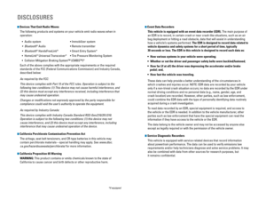
Fuse Locations
If‚Äāany‚Äāelectrical‚Äādevices‚Äāare‚Äānot‚Äāworking,‚Äāturn‚Äāthe‚Äāvehicle‚Äāoff‚Äāand‚Äācheck‚Äāto‚Äāsee‚Äāif‚Äāany‚Äā
applicable‚Äāfuse‚Äāis‚Äāblown.‚ÄāFuse‚Äālocations‚Äāare‚Äāshown‚Äāon‚Äāthe‚Äāfuse‚Äābox‚Äācover.‚ÄāLocate‚Äāthe‚Äā
fuse‚Äāin‚Äāquestion‚Äāby‚Äāthe‚Äāfuse‚Äānumber‚Äāand‚Äābox‚Äācover‚Äānumber.‚Äā
Engine Compartment Fuse Box
Located‚Äāunder‚Äāthe‚Äāhood‚Äānear‚Äāthe‚Äābrake‚Äāfluid‚Äāreservoir.‚ÄāPush‚Äāthe‚Äātabs‚Äāto‚Äāopen‚Äāthe‚Äā
box.
89VSA ECU7.5 A
10 (7.5 A)
11STRLD7.5 A
12 20 A
13Premium Amp*(20 A)
14
15Hazard10 A
16
17IG Coil15 A
18
19Daytime Running Lights(10 A)
20 Passenger’s Power Seat
Reclining (20 A)
21Deicer(15 A)
22
23IGP15 A
24
25Right Headlight Low Beam10 A
26
27MG Clutch7.5 A
28
29Backu p10A
Circuit Protecte dAmps7.5 A
10 A
10 A
15 A
15 A
10 A
20 A
7.5 A
Sub Fan Rly CL
HornStop
IGP2
DBW
Left Headlight Low Beam SMALL
Interior Lights
Heated Door Mirror
*
Injector
Circuit ProtectedAmps
1
EPS70
APower Tailgate(40 A)ABS/VSA FSR20 AABS/VSA Motor40 AE-DPS*(30 A)Main Fuse120 A
2
Main50A
Fuse Box Main
Fuse Box Main 260A
Headlight High Beam Main
ST Magnetic Switch(30 A)
Rear Defogger �
Heater Motor
Front Wiper Main Sub Fan Moto r
Main Fan Motor
3
DC/DC1(30 A)DC/DC2(30 A)IG MAIN(30 A)IG MAIN2(30 A)
4
5��
6
7��
60 A
30 A
30 A
40 A
30 A
20 A
20 A
�
�
�
� (30 A)
*if‚Äāequipped
Ta b
Circuit ProtectedAmps1��2ACG10
A3SRS10A4Fuel Pump15A
5Meter10A6Power Window7.5 A7VB SOL7.5 A
8Passenger’s Side Door Lock
Motor 2 (Unlock)15 A
9Driver’s Side Door Lock
Motor 1 (Unlock )15A
10 (7.5 A)
11Moonroof*(20 A)
12 Accessory Power Socket
(Center Console )20
A
13Washer Main*(15 A)
14 (20A )
15Driver’s Door Lock Motor
(Unlock)10 A
16 (20 A)
17Driver's Power Seat
Reclining*(20 A)
18
19ACC7. 5A
Driver's Power Seat Sliding*
Seat Heaters*
Trailer*
Front Passenger’s Seat
Sliding*(20 A)
2021Daytime Running Lights7.5 A
22
23Wipe r10 A
24
25Audio10 A
26 (20 A)
27Accessory Power Socket
(Front)20A
28 15A
29OPDS7.5A
30 Driver’s Door Lock Motor
(Lock) 10
A
31Smart*(10 A)
32 Passenger’s Side Door
Lock
Motor 2 (Lock )15
A
33Driver’s Side Door Lock
Motor 1 (Lock)15 A
34
35Illumination7.5 A
36 (10 A)
37Front Fog Lights*(20 A)
38
3910 A
40
41Door Loc k20 A
42 Driver’s Side Power
Window 20
A
43Rear Passenger’s Side
Power Window20 A
44 Front Passenger’s Side
Power Window 20
A
45Rear Driver’s Side Power
Window20 A
46
Circuit ProtectedAmps
Washer*
Power Tailgate*
7. 5A
ABS/VSA 7.
5A
A/C 7.5
A
ACC Key Lock
Right Headlight High Beam
��
10 A
Left Headlight High Beam Rear Wiper Main
*
10 A
Small Lights
�
�
Interior Fuse Box
Located‚Äāunder‚Äāthe‚Äādashboard.
*if‚Äāequipped
Fuse‚Äālabel
Fuse‚Äābox