2016 FORD F450 SUPER DUTY clock
[x] Cancel search: clockPage 239 of 507

Only use oils certified for gasoline enginesby the American Petroleum Institute (API).An oil with this trademark symbolconforms to the current engine andemission system protection standards andfuel economy requirements of theInternational Lubricants SpecificationAdvisory Council (ILSAC), comprised ofU.S. and Japanese automobilemanufacturers.
1. Check the engine oil level.
2. If the engine oil level is not within thenormal range, add engine oil thatmeets Ford specifications. SeeCapacities and Specifications for moreinformation.
3. Remove the engine oil filler cap anduse a funnel to pour the engine oil intothe opening.
4.Recheck the engine oil level. Make surethe oil level is not above the normaloperating range on the engine oil leveldipstick.
5. Install the engine oil level dipstick andensure it is fully seated.
6. Fully install the engine oil filler cap byturning the filler cap clockwise untilthree clicks are heard or until the capis fully seated.
OIL CHANGE INDICATOR
RESET
Resetting the Oil Life MonitoringSystem
Only reset the oil life monitoring systemafter changing the engine oil and oil filter.
1.Switch the ignition on. Do not start theengine. For vehicles with push-buttonstart, press and hold the start buttonfor two seconds without pressing thebrake pedal. Do not start the engine.
2.Press the accelerator and brake pedalsat the same time.
3.Keep the accelerator and brake pedalsfully pressed.
4. After three seconds, a messageconfirming that the reset is in progresswill be displayed.
5. After 25 seconds, a messageconfirming that the reset is completewill be displayed.
6. Release the accelerator and brakepedals.
7.The message confirming that the resetis complete will no longer be displayed.
8.Switch the ignition off. For vehicles withpush-button start, press the startbutton to switch the ignition off.
ENGINE COOLANT CHECK
WARNINGS
Do not add engine coolant when theengine is hot. Steam and scaldingliquids released from a hot coolingsystem can burn you badly. Also, you canbe burned if you spill coolant on hot engineparts.
236
Super Duty (TFA) Canada/United States of America, enUSA, First Printing
MaintenanceE142732
Page 249 of 507

6. Release the parking brake. With yourfoot on the brake pedal and with theA/C on, put the vehicle in D and allowthe engine to idle for at least oneminute.
•If you do not allow the engine torelearn its idle trim, the idle qualityof your vehicle may be adverselyaffected until the idle trim iseventually relearned.
7. Drive the vehicle to complete therelearning process
•The vehicle may need to be driven10 mi (16 km) or more to relearn theidle and fuel trim strategy alongwith the ethanol content for flexiblefuel vehicles.
•For flexible fuel vehicles, if you areoperating on E85, you mayexperience poor starts or aninability to start the engine anddriveability problems until the fueltrim and ethanol content have beenrelearned.
If the battery has been disconnected or anew battery has been installed, the clockand radio settings must be reset once thebattery is reconnected.
Always dispose of automotivebatteries in a responsible manner.Follow your local authorized standardsfor disposal. Call your local authorizedrecycling center to find out more aboutrecycling automotive batteries.
Battery Management System (IfEquipped)
The battery management system (BMS)monitors battery conditions and takesactions to extend battery life. If excessivebattery drain is detected, the system maytemporarily disable certain electricalfeatures to protect the battery. Thoseelectrical accessories affected include therear defrost, heated/cooled seats, climate
control fan, heated steering wheel, audioand navigation system. A message may beshown in the information displays to alertthe driver that battery protection actionsare active. These messages are only fornotification that an action is taking place,and not intended to indicate an electricalproblem or that the battery requiresreplacement.
Electrical accessory installation
To ensure proper operation of the BMS,any electrical devices that are added tothe vehicle should not have their groundconnection made directly at the negativebattery post. A connection at the negativebattery post can cause inaccuratemeasurements of the battery conditionand potential incorrect system operation.
Note:Electrical or electronic accessoriesadded to the vehicle by the dealer or theowner may adversely affect batteryperformance and durability, and may alsoaffect the performance of other electricalsystems in the vehicle.
When a battery replacement is required,the battery should only be replaced witha Ford recommended replacement batterywhich matches the electrical requirementsof the vehicle. After battery replacement,or in some cases after charging the batterywith the external charger, the BMS requireseight hours of vehicle sleep time (key offwith doors closed) to relearn the newbattery state of charge. Prior to relearningthe state of charge, the BMS may disableelectrical features (to protect the battery)earlier than normal.
246
Super Duty (TFA) Canada/United States of America, enUSA, First Printing
Maintenance
Page 251 of 507
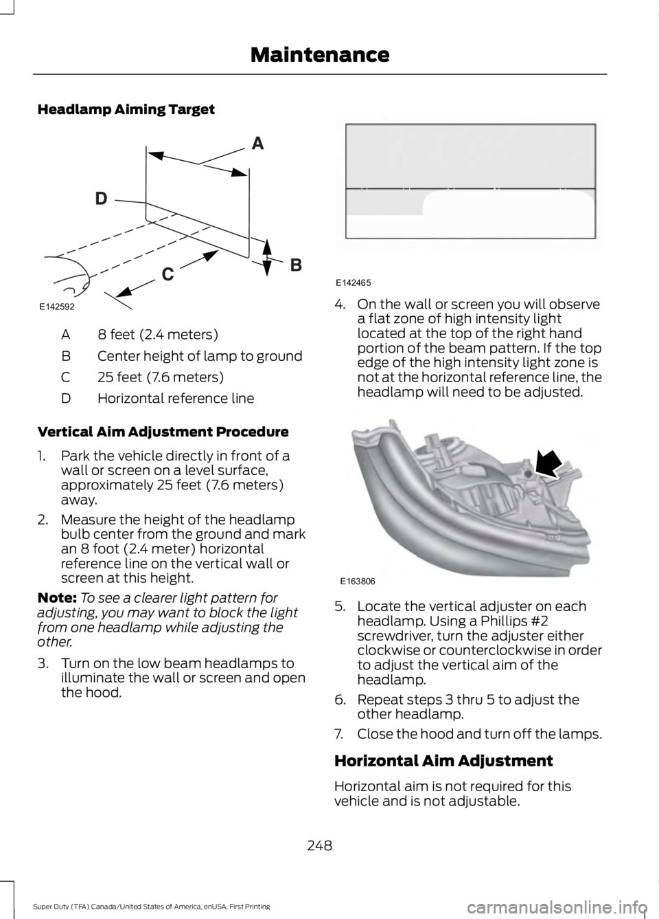
Headlamp Aiming Target
8 feet (2.4 meters)A
Center height of lamp to groundB
25 feet (7.6 meters)C
Horizontal reference lineD
Vertical Aim Adjustment Procedure
1. Park the vehicle directly in front of awall or screen on a level surface,approximately 25 feet (7.6 meters)away.
2. Measure the height of the headlampbulb center from the ground and markan 8 foot (2.4 meter) horizontalreference line on the vertical wall orscreen at this height.
Note:To see a clearer light pattern foradjusting, you may want to block the lightfrom one headlamp while adjusting theother.
3. Turn on the low beam headlamps toilluminate the wall or screen and openthe hood.
4. On the wall or screen you will observea flat zone of high intensity lightlocated at the top of the right handportion of the beam pattern. If the topedge of the high intensity light zone isnot at the horizontal reference line, theheadlamp will need to be adjusted.
5. Locate the vertical adjuster on eachheadlamp. Using a Phillips #2screwdriver, turn the adjuster eitherclockwise or counterclockwise in orderto adjust the vertical aim of theheadlamp.
6. Repeat steps 3 thru 5 to adjust theother headlamp.
7.Close the hood and turn off the lamps.
Horizontal Aim Adjustment
Horizontal aim is not required for thisvehicle and is not adjustable.
248
Super Duty (TFA) Canada/United States of America, enUSA, First Printing
MaintenanceE142592 E142465 E163806
Page 253 of 507
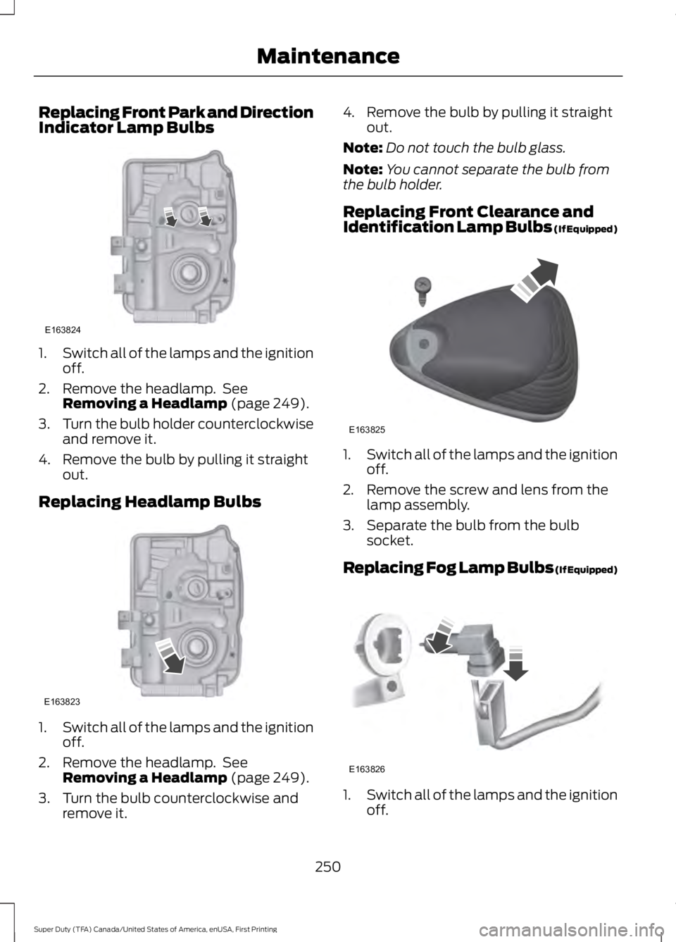
Replacing Front Park and DirectionIndicator Lamp Bulbs
1.Switch all of the lamps and the ignitionoff.
2. Remove the headlamp. SeeRemoving a Headlamp (page 249).
3.Turn the bulb holder counterclockwiseand remove it.
4. Remove the bulb by pulling it straightout.
Replacing Headlamp Bulbs
1.Switch all of the lamps and the ignitionoff.
2. Remove the headlamp. SeeRemoving a Headlamp (page 249).
3. Turn the bulb counterclockwise andremove it.
4. Remove the bulb by pulling it straightout.
Note:Do not touch the bulb glass.
Note:You cannot separate the bulb fromthe bulb holder.
Replacing Front Clearance andIdentification Lamp Bulbs (If Equipped)
1.Switch all of the lamps and the ignitionoff.
2. Remove the screw and lens from thelamp assembly.
3. Separate the bulb from the bulbsocket.
Replacing Fog Lamp Bulbs (If Equipped)
1.Switch all of the lamps and the ignitionoff.
250
Super Duty (TFA) Canada/United States of America, enUSA, First Printing
MaintenanceE163824 E163823 E163825 E163826
Page 254 of 507
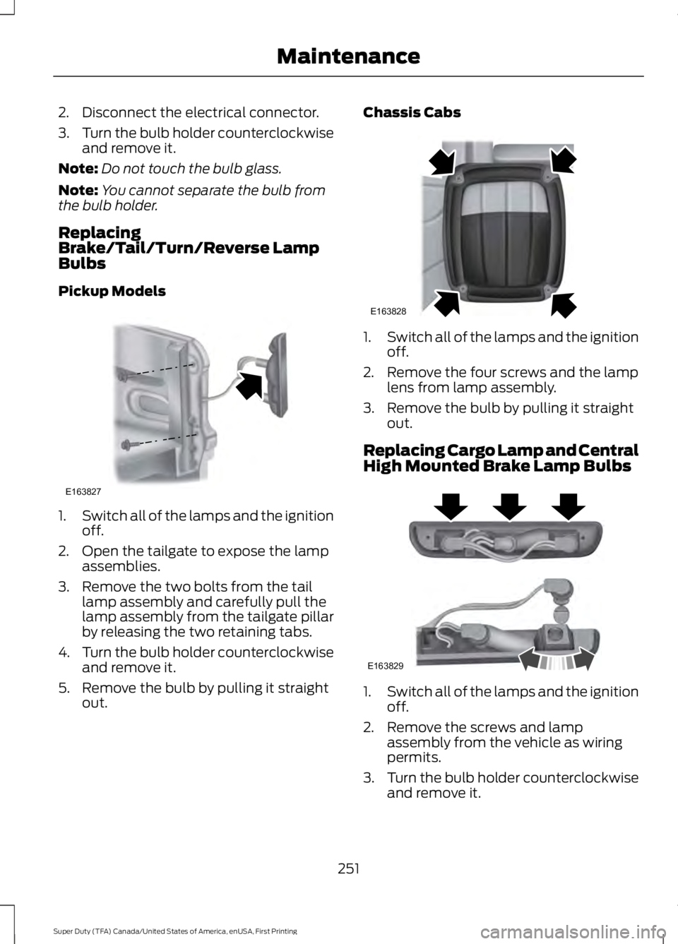
2. Disconnect the electrical connector.
3.Turn the bulb holder counterclockwiseand remove it.
Note:Do not touch the bulb glass.
Note:You cannot separate the bulb fromthe bulb holder.
ReplacingBrake/Tail/Turn/Reverse LampBulbs
Pickup Models
1.Switch all of the lamps and the ignitionoff.
2. Open the tailgate to expose the lampassemblies.
3. Remove the two bolts from the taillamp assembly and carefully pull thelamp assembly from the tailgate pillarby releasing the two retaining tabs.
4.Turn the bulb holder counterclockwiseand remove it.
5. Remove the bulb by pulling it straightout.
Chassis Cabs
1.Switch all of the lamps and the ignitionoff.
2. Remove the four screws and the lamplens from lamp assembly.
3. Remove the bulb by pulling it straightout.
Replacing Cargo Lamp and CentralHigh Mounted Brake Lamp Bulbs
1.Switch all of the lamps and the ignitionoff.
2. Remove the screws and lampassembly from the vehicle as wiringpermits.
3.Turn the bulb holder counterclockwiseand remove it.
251
Super Duty (TFA) Canada/United States of America, enUSA, First Printing
MaintenanceE163827 E163828 E163829
Page 255 of 507
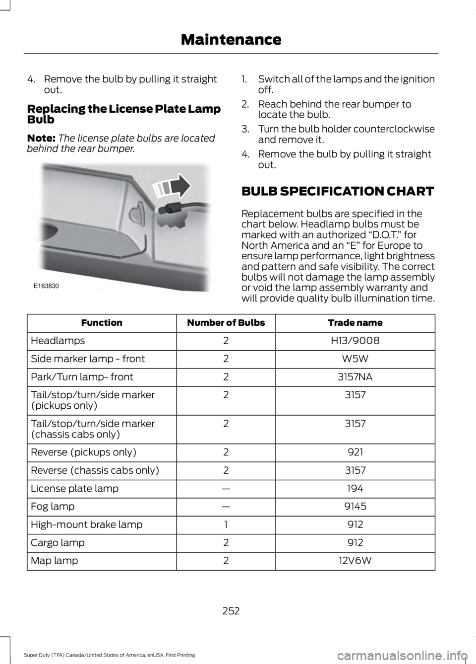
4. Remove the bulb by pulling it straightout.
Replacing the License Plate LampBulb
Note:The license plate bulbs are locatedbehind the rear bumper.
1.Switch all of the lamps and the ignitionoff.
2. Reach behind the rear bumper tolocate the bulb.
3.Turn the bulb holder counterclockwiseand remove it.
4. Remove the bulb by pulling it straightout.
BULB SPECIFICATION CHART
Replacement bulbs are specified in thechart below. Headlamp bulbs must bemarked with an authorized “D.O.T.” forNorth America and an “E” for Europe toensure lamp performance, light brightnessand pattern and safe visibility. The correctbulbs will not damage the lamp assemblyor void the lamp assembly warranty andwill provide quality bulb illumination time.
Trade nameNumber of BulbsFunction
H13/90082Headlamps
W5W2Side marker lamp - front
3157NA2Park/Turn lamp- front
31572Tail/stop/turn/side marker(pickups only)
31572Tail/stop/turn/side marker(chassis cabs only)
9212Reverse (pickups only)
31572Reverse (chassis cabs only)
194—License plate lamp
9145—Fog lamp
9121High-mount brake lamp
9122Cargo lamp
12V6W2Map lamp
252
Super Duty (TFA) Canada/United States of America, enUSA, First Printing
MaintenanceE163830
Page 292 of 507

•To reduce the chances of interferencefrom another vehicle, perform thesystem reset procedure at least threefeet (one meter) away from anotherFord Motor Company vehicleundergoing the system reset procedureat the same time.
•Do not wait more than two minutesbetween resetting each tire sensor orthe system will time-out and the entireprocedure will have to be repeated onall four wheels.
•A double horn will sound indicating theneed to repeat the procedure.
Performing the System Reset Procedure
Read the entire procedure beforeattempting.
1. Drive the vehicle above 20 mph (32km/h) for at least two minutes, thenpark in a safe location where you caneasily get to all four tires and haveaccess to an air pump.
2.Place the ignition in the off position andkeep the key in the ignition.
3. Cycle the ignition to the on positionwith the engine off.
4. Turn the hazard flashers on then offthree times. You must accomplish thiswithin 10 seconds. If the reset modehas been entered successfully, the hornwill sound once, the system indicatorwill flash and a message is shown inthe information display. If this does notoccur, please try again starting at Step2. If after repeated attempts to enterthe reset mode, the horn does notsound, the system indicator does notflash and no message is shown in theinformation display, seek service fromyour authorized dealer.
5. Train the tire pressure monitoringsystem sensors in the tires using thefollowing system reset sequencestarting with the left front tire in thefollowing clockwise order: Left front(driver's side front tire), Right front(passenger's side front tire), Right rear(passenger's side rear tire), Left rear(driver's side rear tire).
6. Remove the valve cap from the valvestem on the left front tire. Decrease theair pressure until the horn sounds.Note: The single horn chirp confirmsthat the sensor identification code hasbeen learned by the module for thisposition. If a double horn is heard, thereset procedure was unsuccessful, andyou must repeat it.
7. Remove the valve cap from the valvestem on the right front tire. Decreasethe air pressure until the horn sounds.
8. Remove the valve cap from the valvestem on the right rear tire. Decrease theair pressure until the horn sounds.
9. Remove the valve cap from the valvestem on the left rear tire. Decrease theair pressure until the horn sounds.Training is complete after the hornsounds for the last tire trained (driver'sside rear tire), the system indicatorstops flashing, and a message is shownin the information display.
10.Turn the ignition off. If two short hornbeeps are heard, the reset procedurewas unsuccessful and you mustrepeat it. If after repeating theprocedure and two short beeps areheard when the ignition is turned tooff, seek assistance from yourauthorized dealer.
289
Super Duty (TFA) Canada/United States of America, enUSA, First Printing
Wheels and Tires
Page 296 of 507
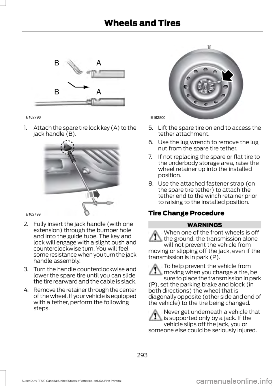
1.Attach the spare tire lock key (A) to thejack handle (B).
2. Fully insert the jack handle (with oneextension) through the bumper holeand into the guide tube. The key andlock will engage with a slight push andcounterclockwise turn. You will feelsome resistance when you turn the jackhandle assembly.
3.Turn the handle counterclockwise andlower the spare tire until you can slidethe tire rearward and the cable is slack.
4.Remove the retainer through the centerof the wheel. If your vehicle is equippedwith a tether, perform the followingsteps.
5.Lift the spare tire on end to access thetether attachment.
6. Use the lug wrench to remove the lugnut from the spare tire tether.
7. If not replacing the spare or flat tire tothe underbody storage area, raise thewheel retainer up into the installedposition.
8. Use the attached fastener strap (onthe spare tire tether) to attach thetether end to the winch retainer priorto raising to the installed position.
Tire Change Procedure
WARNINGS
When one of the front wheels is offthe ground, the transmission alonewill not prevent the vehicle frommoving or slipping off the jack, even if thetransmission is in park (P).
To help prevent the vehicle frommoving when you change a tire, besure to place the transmission in park(P), set the parking brake and block (inboth directions) the wheel that isdiagonally opposite (other side and end ofthe vehicle) to the tire being changed.
Never get underneath a vehicle thatis supported only by a jack. If thevehicle slips off the jack, you orsomeone else could be seriously injured.
293
Super Duty (TFA) Canada/United States of America, enUSA, First Printing
Wheels and TiresE162798
AB
AB E162799 E162800