2016 FORD F450 SUPER DUTY warning
[x] Cancel search: warningPage 192 of 507
GCW (Gross Combined Weight)- is the Gross Vehicle Weight plusthe weight of the fully loadedtrailer.
GCWR (Gross CombinedWeight Rating) - is the maximumallowable weight of the vehicleand the loaded trailer, includingall cargo and passengers, that thevehicle can handle without riskingdamage. (Important: The towingvehicle’s braking system is ratedfor operation at Gross VehicleWeight Rating, not at GrossCombined Weight Rating.)Separate functional brakes shouldbe used for safe control of towedvehicles and for trailers where theGross Combined Weight of thetowing vehicle plus the trailerexceed the Gross Vehicle WeightRating of the towing vehicle.TheGross Combined Weight mustnever exceed the GrossCombined Weight Rating.
Maximum Loaded TrailerWeight - is the highest possibleweight of a fully loaded trailer thevehicle can tow. It assumes avehicle with mandatory options,driver and front passenger weight(150 pounds [68 kilograms]each), no cargo weight (internalor external) and a tongue load of10–15% (conventional trailer) orking pin weight of 15–25% (fifthwheel trailer). Consult anauthorized dealer (or the RV andTrailer Towing Guide available at
an authorized dealer) for moredetailed information.
Tongue Load or Fifth WheelKing Pin Weight - refers to theamount of the weight that a trailerpushes down on a trailer hitch.
Examples: For a 5000 pound(2268 kilogram) conventionaltrailer, multiply 5000 by 0.10 and0.15 to obtain a proper tongueload range of 500 to 750 pounds(227 to 340 kilograms). For an11500 pound (5216 kilogram) fifthwheel trailer, multiply by 0.15 and0.25 to obtain a proper king pinload range of 1725 to 2875 pounds(782 to 1304 kilograms).
WARNINGS
Do not exceed the GVWR orthe GAWR specified on theSafety Compliance CertificationLabel.
Do not use replacement tireswith lower load carryingcapacities than the original tiresbecause they may lower thevehicle’s GVWR and GAWRlimitations. Replacement tireswith a higher limit than the originaltires do not increase the GVWRand GAWR limitations.
Exceeding any vehicle weightrating limitation could resultin serious damage to the vehicleand/or personal injury.
Steps for determining thecorrect load limit:
189
Super Duty (TFA) Canada/United States of America, enUSA, First Printing
Load Carrying
Page 194 of 507
be: 635 kilograms - (2 x 99kilograms) - (12 x 45 kilograms) =635 - 198 - 540 = -103 kilograms.You will need to reduce the loadweight by at least 240 pounds(104 kilograms). If you removethree 100-pound (45-kilogram)cement bags, then the loadcalculation would be: 1400 - (2 x220) - (9 x 100) = 1400 - 440 -900 = 60 pounds. Now you havethe load capacity to transport thecement and your friend home. Inmetric units, the calculation wouldbe: 635 kilograms - (2 x 99kilograms) - (9 x 45 kilograms) =635 - 198 - 405 = 32 kilograms.
The above calculations alsoassume that the loads arepositioned in your vehicle in amanner that does not overloadthe Front or the Rear Gross AxleWeight Rating specified for yourvehicle on the Safety ComplianceCertification Label. The label shallbe affixed to either the door hingepillar, door-latch post, or the dooredge that meets the door-latchpost, next to the driver seatingposition.
Special Loading Instructionsfor Owners of Pick-up Trucksand Utility-type Vehicles
WARNING
Loaded vehicles may handledifferently than unloadedvehicles. Extra precautions, suchas slower speeds and increasedstopping distance, should betaken when driving a heavilyloaded vehicle.
Your vehicle can haul more cargoand people than most passengercars. Depending upon the typeand placement of the load,hauling cargo and people mayraise the center of gravity of thevehicle.
191
Super Duty (TFA) Canada/United States of America, enUSA, First Printing
Load Carrying
Page 195 of 507
TOWING A TRAILER
WARNINGS
Do not exceed the GVWR orthe GAWR specified on thecertification label.
Towing trailers beyond themaximum recommendedgross trailer weight exceeds thelimit of the vehicle and couldresult in engine damage,transmission damage, structuraldamage, loss of vehicle control,vehicle rollover and personalinjury.
Your vehicle may have electricalitems, such as fuses or relays,related to towing. See the Fuseschapter.
Your vehicle's load capacitydesignation is by weight, not byvolume, so you cannot necessarilyuse all available space whenloading a vehicle or trailer.
Towing a trailer places an extraload on your vehicle's engine,transmission, axle, brakes, tiresand suspension. Inspect thesecomponents periodically during,and after, any towing operation.
Load Placement
To help minimize how trailermovement affects your vehiclewhen driving:
•Load the heaviest items closestto the trailer floor.
•Load the heaviest itemscentered between the left andright side trailer tires.
•Load the heaviest items abovethe trailer axles or just slightlyforward toward the trailertongue. Do not allow the finaltrailer tongue weight to goabove or below 10-15% of theloaded trailer weight.
•Select a tow bar with thecorrect rise or drop. When boththe loaded vehicle and trailerare connected, the trailer frameshould be level, or slightlyangled down toward yourvehicle, when viewed from theside.
When driving with a trailer orpayload, a slight takeoff vibrationor shudder may be present due tothe increased payload weight.Additional information regardingproper trailer loading and settingyour vehicle up for towing islocated in another chapter of thismanual. See Load Limit (page185).
You can also find information inthe RV & Trailer Towing Guideavailable at your authorizeddealer, or online.
192
Super Duty (TFA) Canada/United States of America, enUSA, First Printing
Towing
Page 196 of 507
RV & Trailer Towing Guide Online
http://www.fleet.ford.com/towing-guides/Website
TRAILER SWAY CONTROL (If
Equipped)
WARNING
Turning off trailer sway controlincreases the risk of loss of vehiclecontrol, serious injury or death. Forddoes not recommend disabling this featureexcept in situations where speed reductionmay be detrimental (such as hill climbing),the driver has significant trailer towingexperience, and can control trailer swayand maintain safe operation.
Note:This feature does not prevent trailersway, but reduces it once it begins.
Note:This feature cannot stop all trailersfrom swaying.
Note:In some cases, if vehicle speed is toohigh, the system may activate multipletimes, gradually reducing vehicle speed.
This feature applies your vehicle brakes atindividual wheels and, if necessary, reducesengine power. If the trailer begins to sway,the stability control light flashes and themessage TRAILER SWAY REDUCESPEED appears in the information display.The first thing to do is slow your vehicledown, then pull safely to the side of theroad and check for proper tongue load andtrailer load distribution. See LoadCarrying (page 185).
RECOMMENDED TOWING
WEIGHTS
Note:Make sure to take intoconsideration trailer frontal area.Do not exceed 60 feet2 (5.6
meters2) trailer frontal area for
conventional trailers. Do notexceed 75 feet2 (6.9 meters2) trailer
frontal area for 5th wheel andgooseneck trailers.
Note:Exceeding this limitationmay significantly reduce theperformance of your towingvehicle. Selecting a trailer with alow aerodynamic drag and roundedfront design helps optimizeperformance and fuel economy.
Note:For high altitude operation,reduce the gross combined weightby 2% per 1000 feet (300 meters)starting at the 1000 foot (300meter) elevation point.
Note:Certain states requireelectric trailer brakes for trailersover a specified weight. Be sure tocheck state regulations for thisspecified weight. The maximumtrailer weights listed may be limitedto this specified weight, as yourvehicle's electrical system may notinclude the wiring connector
needed to use electric trailerbrakes.
193
Super Duty (TFA) Canada/United States of America, enUSA, First Printing
Towing
Page 201 of 507
Fixed guidelines are always shown in thedisplay, but the active guidelines onlydisplay when the steering wheel is turned.To use active guidelines, turn the steeringwheel to point the guidelines toward anintended path. If the steering wheelposition is changed while reversing, yourvehicle might deviate from the originalintended path.
The active guidelines fade in and outdepending on the steering wheel position.The active guidelines are not shown whenthe steering wheel position is straight.
Always use caution while reversing.Objects in the red zone are closest to yourvehicle and objects in the green zone arefarther away. Objects are getting closer toyour vehicle as they move from the greenzone to the yellow or red zones. Use theside view mirrors and rear view mirror toget better coverage on both sides and rearof your vehicle.
Refer to the Rear View Camera section foradditional information. See Rear ViewCamera (page 180).
Hitches
WARNING
On pick-up trucks, the trailer hitchprovided on this vehicle enhancescrash protection for the fuel system.Do not remove!
Do not use a hitch that either clamps ontothe bumper or attaches to the axle. Youmust distribute the load in your trailer sothat 10-15% for conventional towing or15-25% for fifth wheel towing of the totalweight of the trailer is on the tongue.
Weight-distributing Hitches
WARNING
Do not adjust a weight-distributinghitch to any position where the rearbumper of the vehicle is higher thanit was before attaching the trailer. Doingso will defeat the function of theweight-distributing hitch, which may causeunpredictable handling, and could resultin serious personal injury.
When hooking-up a trailer using aweight-distributing hitch, always use thefollowing procedure:
1. Park the loaded vehicle, without thetrailer, on a level surface.
2. Measure the height to the top of yourvehicle's front wheel opening on thefender. This is H1.
3.Attach the loaded trailer to your vehiclewithout the weight-distributing barsconnected.
4. Measure the height to the top of yourvehicle's front wheel opening on thefender a second time. This is H2.
5. Install and adjust the tension in theweight-distributing bars so that theheight of your vehicle's front wheelopening on the fender is approximatelyhalfway between H1 and H2.
6.Check that the trailer is level or slightlynose down toward your vehicle. If not,adjust the ball height accordingly andrepeat Steps 2-6.
Once the trailer is level or slightly nosedown toward the vehicle:
•Lock the bar tension adjuster in place.
•Check that the trailer tongue securelyattaches and locks onto the hitch.
•Install safety chains, lighting, and trailerbrake controls as required by law or thetrailer manufacturer.
198
Super Duty (TFA) Canada/United States of America, enUSA, First Printing
Towing
Page 202 of 507
Fifth-wheel Trailer Hitch (If Equipped)
WARNINGS
The mounting pads in the bed arespecifically designed for certainfifth-wheel trailer hitches andgooseneck ball hitches. Do not use thesemounting pads for other purposes. Doingso could result in vehicle structuraldamage, loss of vehicle control, andpersonal injury. Contact an authorizeddealer to purchase gooseneck andfifth-wheel hitches that are compatiblewith your vehicle.
Towing trailers beyond the maximumlimit of the towing system couldresult in vehicle structural damage,loss of vehicle control and personal injury.
The hitch rating listed on the trailerhitch label is the maximum possibletrailer rating. To find the maximumtrailer weight allowed for your specificvehicle, consult an authorized dealer or theRV & Trailer Towing Guide provided by anauthorized dealer.
Your vehicle may be equipped with afifth-wheel prep package. This packageenables your vehicle to accept certainfifth-wheel trailer hitches and gooseneckball hitches. The fifth-wheel trailer hitchattaches to the four mounting pads in thepick-up bed. An optional 7-pin trailer wiringconnector may be in the bed as well. Thegooseneck ball hitch is a separatemounting pad from the fifth-wheel hitch,located in the center of the bed.
Shorter pick-up boxes, such as the 6½-footbox on the F-250 and F-350, provide lessclearance between the cab and thefifth-wheel and gooseneck trailercompared to longer box pick-ups, such asan 8-foot box on the F-250 or F-350. Whenselecting a trailer and tow vehicle, it iscritical to check that this combinationprovides clearance between the front of
the trailer and tow vehicle for turns up to90 degrees. Failure to follow thisrecommendation could result in the trailercontacting the cab of the tow vehicleduring tight turns that are typical duringlow-speed parking and turning maneuvers.This contact could result in damage to thetrailer and tow vehicle.
Safety Chains
Note:Do not attach safety chains to thebumper.
Always connect the safety chains to theframe or hook retainers of your vehiclehitch.
To connect the safety chains, cross thechains under the trailer tongue and allowenough slack for turning tight corners. Donot allow the chains to drag on the ground.
Trailer Brakes
WARNING
Do not connect a trailer's hydraulicbrake system directly to yourvehicle's brake system. Your vehiclemay not have enough braking power andyour chances of having a collision greatlyincrease.
Electric brakes and manual, automatic orsurge-type trailer brakes are safe if youinstall them properly and adjust them tothe manufacturer's specifications. Thetrailer brakes must meet local and federalregulations.
The rating for the tow vehicle's brakingsystem operation is at the gross vehicleweight rating, not the gross combinedweight rating.
Separate functioning brake systemsare required for safe control of towedvehicles and trailers weighing morethan 1500 pounds (680 kilograms)when loaded.
199
Super Duty (TFA) Canada/United States of America, enUSA, First Printing
Towing
Page 203 of 507
Integrated Trailer Brake Controller
(If Equipped)
WARNING
The Ford trailer brake controller hasbeen verified to be compatible withtrailers having electric-actuateddrum brakes (one to four axles) and someelectric-over-hydraulic brakes. It will notactivate hydraulic surge-style trailerbrakes. It is the responsibility of thecustomer to ensure that the trailer brakesare adjusted appropriately, functioningnormally and all electric connections areproperly made. Failure to do so may resultin loss of vehicle control, crash or seriousinjury.
When used properly, the trailer brakecontroller assists in smooth and effectivetrailer braking by powering the trailer’selectric or electric-over-hydraulic brakeswith a proportional output based on thetowing vehicle’s brake pressure.
You can adjust the amount of initial trailerbrake output by selecting one of threesettings through the message center.
Ford has tested the trailer brake controllerto be compatible with several majorbrands of electric-over-hydraulic trailerbrakes. Contact an authorized dealer forinformation on which brands you can use.
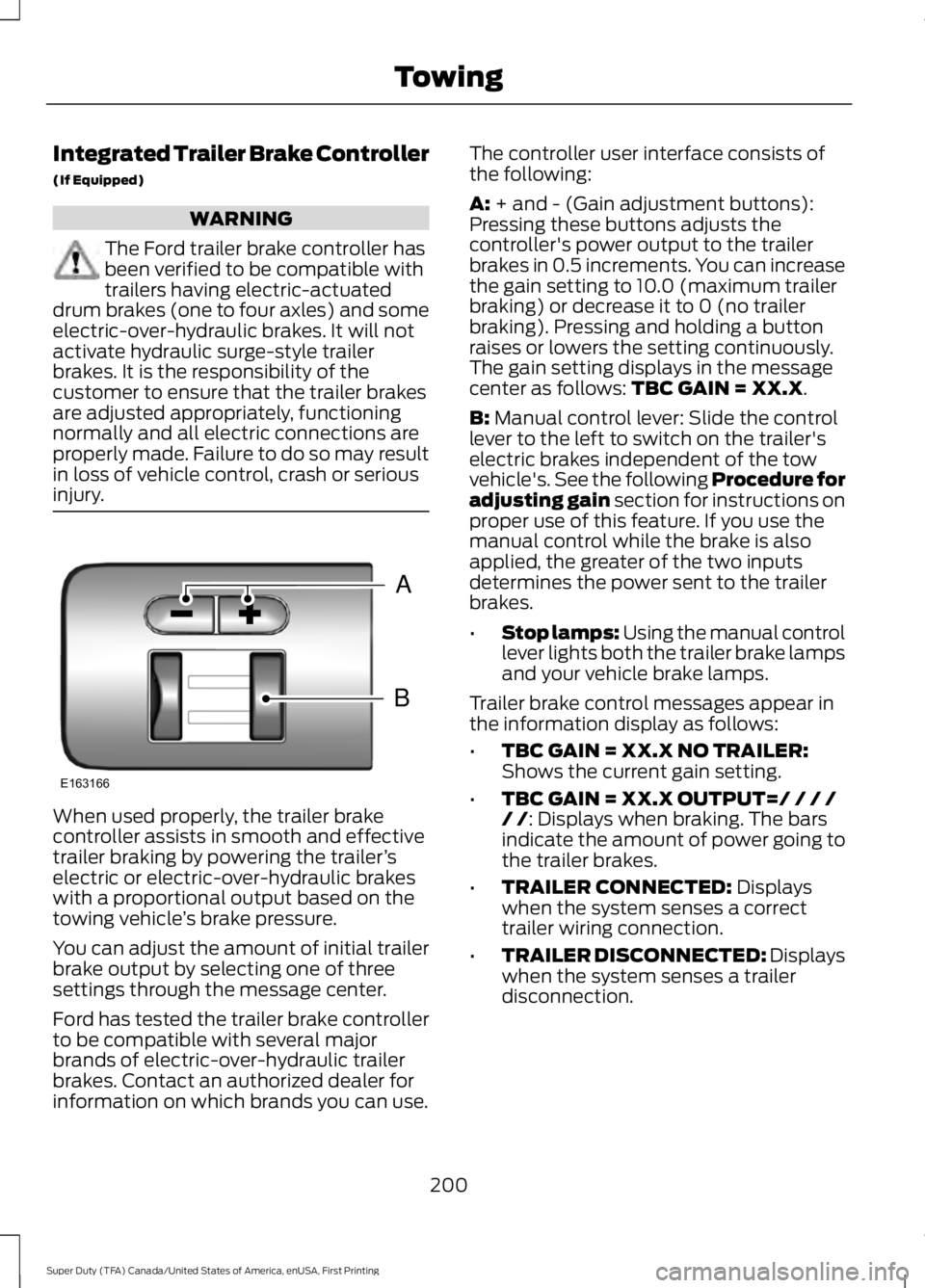
The controller user interface consists ofthe following:
A: + and - (Gain adjustment buttons):Pressing these buttons adjusts thecontroller's power output to the trailerbrakes in 0.5 increments. You can increasethe gain setting to 10.0 (maximum trailerbraking) or decrease it to 0 (no trailerbraking). Pressing and holding a buttonraises or lowers the setting continuously.The gain setting displays in the messagecenter as follows: TBC GAIN = XX.X.
B: Manual control lever: Slide the controllever to the left to switch on the trailer'selectric brakes independent of the towvehicle's. See the following Procedure foradjusting gain section for instructions onproper use of this feature. If you use themanual control while the brake is alsoapplied, the greater of the two inputsdetermines the power sent to the trailerbrakes.
•Stop lamps: Using the manual controllever lights both the trailer brake lampsand your vehicle brake lamps.
Trailer brake control messages appear inthe information display as follows:
•TBC GAIN = XX.X NO TRAILER:Shows the current gain setting.
•TBC GAIN = XX.X OUTPUT=/ / / // /: Displays when braking. The barsindicate the amount of power going tothe trailer brakes.
•TRAILER CONNECTED: Displayswhen the system senses a correcttrailer wiring connection.
•TRAILER DISCONNECTED: Displayswhen the system senses a trailerdisconnection.
200
Super Duty (TFA) Canada/United States of America, enUSA, First Printing
TowingB
A
E163166
Page 204 of 507
Trailer Brake Effort Setting
The trailer brake controller allows the userto customize how aggressively the trailerbrakes engage. The default value is "Low"and is the recommended setting for mosttrailers. If your trailer's brakes require moreinitial voltage, or if you prefer moreaggressive trailer braking, then select eitherthe "Medium" or the "High" setting. SeeInformation Displays (page 89).
Procedure for Adjusting Gain
Note:Only perform this procedure in atraffic-free environment at speeds ofapproximately 20-25 mph (30-40 km/h).
The gain setting adjusts the trailer brakecontroller for the specific towing condition.You should change the setting as towingconditions change. Changes to towingconditions include trailer load, vehicle load,road conditions and weather.
The gain should be set to provide themaximum trailer braking assistance whilemaking sure the trailer wheels do not lockwhen using the brakes. Locked trailerwheels may lead to trailer instability.
1.Make sure the trailer brakes are in goodworking condition, functioning normallyand properly adjusted. See your trailerdealer if necessary.
2. Hook up the trailer and make theelectrical connections according to thetrailer manufacturer's instructions.
3. When you plug in a trailer with electricor electric-over-hydraulic brakes,TRAILER CONNECTED appears inthe information display.
4. Use the gain adjustment (+ and -)buttons to increase or decrease thegain setting to the desired startingpoint. A gain setting of 6.0 is a goodstarting point for heavier loads.
5. In a traffic-free environment, tow thetrailer on a dry, level surface at a speedof 20-25 mph (30-40 km/h) andsqueeze the manual control levercompletely.
6. If the trailer wheels lock up, indicatedby squealing tires, reduce the gainsetting. If the trailer wheels turn freely,increase the gain setting. Repeat Steps5 and 6 until the gain setting is at apoint just below trailer wheel lock-up.If towing a heavier trailer, trailer wheellock-up may not be attainable evenwith the maximum gain setting of 10.
Information Display Warning Messages
Note:An authorized dealer can diagnosethe trailer brake controller to determineexactly which trailer fault has occurred.However, your Ford warranty does not coverthis diagnosis if the fault is with the trailer.
TRAILER BRAKE MODULE FAULT
Displays in response to faults sensed bythe trailer brake controller, accompaniedby a single tone. If this message appears,contact an authorized dealer as soon aspossible for diagnosis and repair. Thecontroller may still function, but withdegraded performance.
WIRING FAULT ON TRAILER
Displays when there is a short circuit onthe electric brake output wire.
If this message displays, with no trailerconnected, the problem is with your vehiclewiring or trailer brake controller. Contactan authorized dealer.
201
Super Duty (TFA) Canada/United States of America, enUSA, First Printing
Towing