2016 FORD F450 SUPER DUTY light
[x] Cancel search: lightPage 236 of 507
2. Go to the front of the vehicle andlocate the secondary release lever,which is located under the front of thehood, to your right of the center of thevehicle (driver's side), toward theheadlight.
3. Release the hood latch by pushing thesecondary release lever to your left,toward the center of the vehicle.
4. Raise the hood.
5.To close the hood, lower the hood andallow it to drop the last 8 to 11 inches(20 to 30 centimeters).
Note:Make sure that the hood is closedproperly.
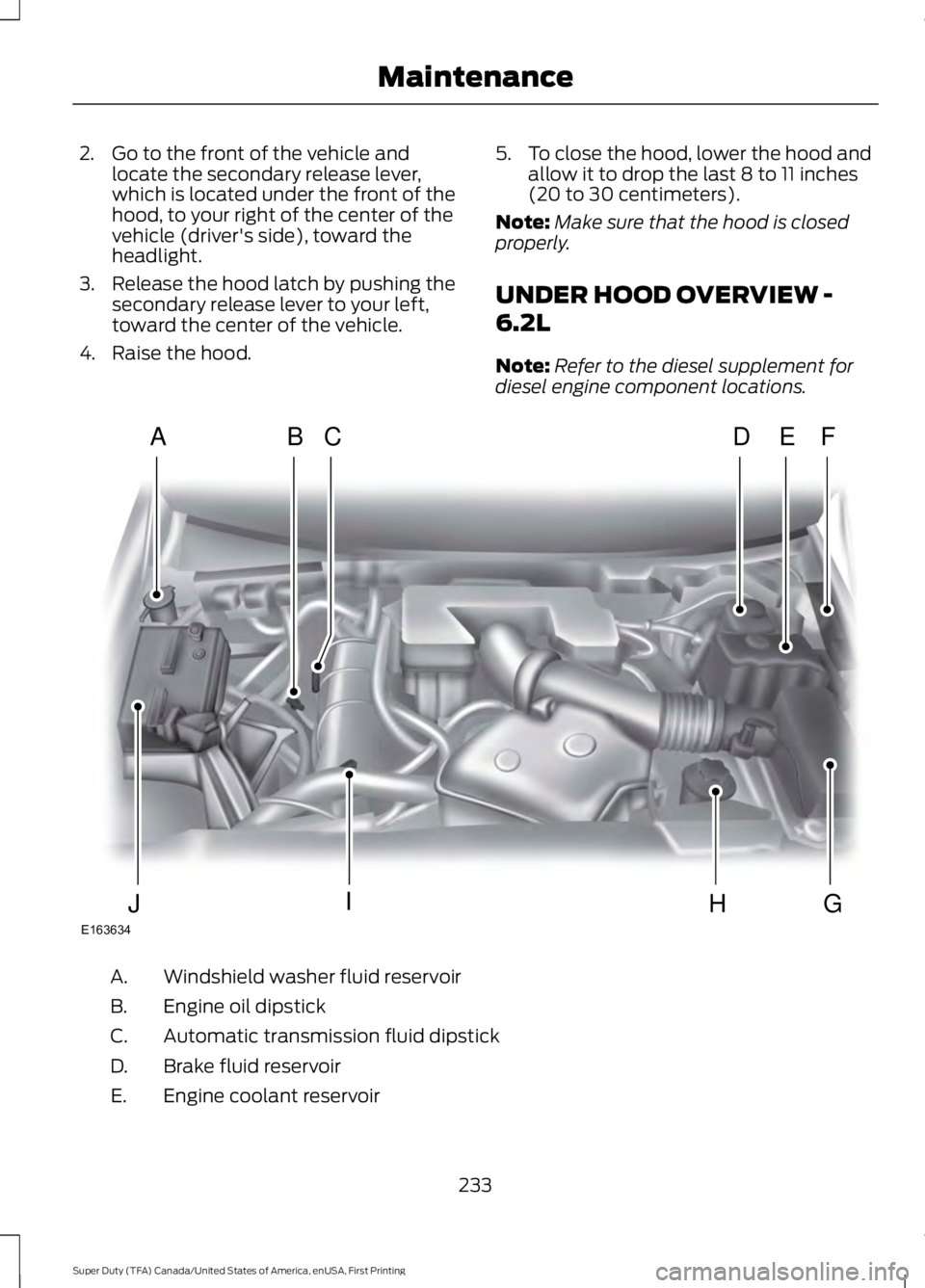
UNDER HOOD OVERVIEW -
6.2L
Note:Refer to the diesel supplement fordiesel engine component locations.
Windshield washer fluid reservoirA.
Engine oil dipstickB.
Automatic transmission fluid dipstickC.
Brake fluid reservoirD.
Engine coolant reservoirE.
233
Super Duty (TFA) Canada/United States of America, enUSA, First Printing
MaintenanceE163634
ADFEBC
GHIJ
Page 240 of 507
WARNINGS
Do not put engine coolant in thewindshield washer fluid container. Ifsprayed on the windshield, enginecoolant could make it difficult to seethrough the windshield.
To reduce the risk of personal injury,make sure the engine is cool beforeunscrewing the coolant pressurerelief cap. The cooling system is underpressure; steam and hot liquid can comeout forcefully when the cap is loosenedslightly.
Do not add coolant further than theMAX mark.
Note:If your vehicle is equipped with adiesel engine, refer to the DieselSupplement.
When the engine is cold, check theconcentration and level of the enginecoolant at the intervals listed in thescheduled maintenance information. SeeScheduled Maintenance (page 453).
Note:Make sure that the level is betweenthe MIN and MAX marks on the coolantreservoir.
Note:Coolant expands when it is hot. Thelevel may extend beyond the MAX mark.
Note:If the level is at the MIN mark, belowthe MIN mark, or empty, add coolantimmediately. See Adding Engine Coolantin this chapter.
The coolant concentration should bemaintained within 48% to 50%, whichequates to a freeze point between -30°F(-34°C) and -34°F (-37°C).
Note:For best results, coolantconcentration should be tested with arefractometer such as Robinair® Coolantand Battery Refractometer 75240. We donot recommend the use of hydrometers orcoolant test strips for measuring coolantconcentrations.
Note:Automotive fluids are notinterchangeable. Do not use engine coolantor antifreeze or windshield washer fluidoutside of its specified function and vehiclelocation.
Adding Engine Coolant
Note:Do not use stop leak pellets, coolingsystem sealants, or additives as they cancause damage to the engine cooling orheating systems. This damage would notbe covered under your vehicle’s warranty.
Note:During normal vehicle operation, theengine coolant may change color fromorange to pink or light red. As long as theengine coolant is clear and uncontaminated,this color change does not indicate theengine coolant has degraded nor does itrequire the engine coolant to be drained, thesystem to be flushed, or the engine coolantto be replaced.
237
Super Duty (TFA) Canada/United States of America, enUSA, First Printing
Maintenance
Page 242 of 507
What You Should Know About Fail-Safe Cooling
If the engine coolant supply is depleted,this feature allows the vehicle to be driventemporarily before incremental componentdamage is incurred. The “fail-safe”distance depends on ambienttemperatures, vehicle load and terrain.
How Fail-Safe Cooling Works
If the engine begins to overheat, the enginecoolant temperature gauge will move tothe red (hot) area and:
The coolant temperaturewarning light will illuminate.
The service engine soonindicator will illuminate.
If the engine reaches a presetover-temperature condition, the enginewill automatically switch to alternatingcylinder operation. Each disabled cylinderacts as an air pump and cools the engine.
When this occurs the vehicle will stilloperate. However:
•The engine power will be limited.
•The air conditioning system will bedisabled.
Continued operation will increase theengine temperature and the engine willcompletely shut down, causing steeringand braking effort to increase.
Once the engine temperature cools, theengine can be re-started. Take your vehicleto an authorized dealer as soon as possibleto minimize engine damage.
When Fail-Safe Mode Is Activated
WARNINGS
Fail-safe mode is for use duringemergencies only. Operate thevehicle in fail-safe mode only as longas necessary to bring the vehicle to rest ina safe location and seek immediate repairs.When in fail-safe mode, the vehicle willhave limited power, will not be able tomaintain high-speed operation, and maycompletely shut down without warning,potentially losing engine power, powersteering assist, and power brake assist,which may increase the possibility of acrash resulting in serious injury.
Never remove the coolant reservoircap while the engine is running or hot.
You have limited engine power when in thefail-safe mode, so drive the vehicle withcaution. The vehicle will not be able tomaintain high-speed operation and theengine will run rough. Remember that theengine is capable of completely shuttingdown automatically to prevent enginedamage, therefore:
1. Pull off the road as soon as safelypossible and turn off the engine.
2. Arrange for the vehicle to be taken toan authorized dealer.
3. If this is not possible, wait a shortperiod for the engine to cool.
4. Check the coolant level and replenishif low.
5. Re-start the engine and take yourvehicle to an authorized dealer.
Note:Driving the vehicle without repairingthe engine problem increases the chance ofengine damage. Take your vehicle to anauthorized dealer as soon as possible.
239
Super Duty (TFA) Canada/United States of America, enUSA, First Printing
Maintenance
Page 248 of 507
CHANGING THE 12V BATTERY
WARNINGS
This vehicle may be equipped withmore than one battery, removal ofcable from only one battery does notdisconnect the vehicle electrical system.Be sure to disconnect cables from allbatteries when disconnecting power.Failure to do so may cause seriouspersonal injury or property damage.
Batteries normally produce explosivegases which can cause personalinjury. Therefore, do not allowflames, sparks or lighted substances tocome near the battery. When working nearthe battery, always shield your face andprotect your eyes. Always provide properventilation.
When lifting a plastic-cased battery,excessive pressure on the end wallscould cause acid to flow through thevent caps, resulting in personal injury anddamage to the vehicle or battery. Lift thebattery with a battery carrier or with yourhands on opposite corners.
Keep batteries out of reach ofchildren. Batteries contain sulfuricacid. Avoid contact with skin, eyes orclothing. Shield your eyes when workingnear the battery to protect against possiblesplashing of acid solution. In case of acidcontact with skin or eyes, flushimmediately with water for a minimum of15 minutes and get prompt medicalattention. If acid is swallowed, call aphysician immediately.
Note:If your battery has a cover/shield,make sure it is reinstalled after the batteryhas been cleaned or replaced.
Note:Battery posts, terminals and relatedaccessories contain lead and leadcompounds. Wash hands after handling.
Note:Electrical or electronic accessoriesor components added to the vehicle by thedealer or the owner may adversely affectbattery performance and durability.
Your vehicle is equipped with a Motorcraftmaintenance-free battery which normallydoes not require additional water duringits life of service.
For longer, trouble-free operation, keep thetop of the battery clean and dry. Also,make certain the battery cables are alwaystightly fastened to the battery terminals.
If you see any corrosion on the battery orterminals, remove the cables from theterminals and clean with a wire brush. Youcan neutralize the acid with a solution ofbaking soda and water.
It is recommended that the negativebattery cable terminal be disconnectedfrom the battery if you plan to store yourvehicle for an extended period of time.
Because your vehicle’s engine iselectronically controlled by a computer,some control conditions are maintainedby power from the battery. When thebattery is disconnected or a new batteryis installed, the engine must relearn its idleand fuel trim strategy for optimumdriveability and performance. Flexible fuelvehicles (FFV) must also relearn theethanol content of the fuel for optimumdriveability and performance. To begin thisprocess
1. With the vehicle at a complete stop,set the parking brake.
2. Put the gearshift in P, turn off allaccessories.
3. Start the engine. Run the engine untilit reaches normal operatingtemperature.
4.Allow the engine to idle for at least oneminute.
5. Turn the A/C on and allow the engineto idle for at least one minute.
245
Super Duty (TFA) Canada/United States of America, enUSA, First Printing
Maintenance
Page 251 of 507
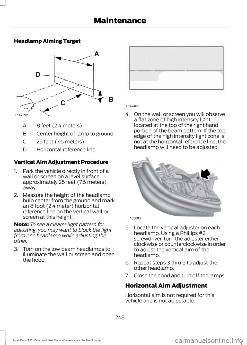
Headlamp Aiming Target
8 feet (2.4 meters)A
Center height of lamp to groundB
25 feet (7.6 meters)C
Horizontal reference lineD
Vertical Aim Adjustment Procedure
1. Park the vehicle directly in front of awall or screen on a level surface,approximately 25 feet (7.6 meters)away.
2. Measure the height of the headlampbulb center from the ground and markan 8 foot (2.4 meter) horizontalreference line on the vertical wall orscreen at this height.
Note:To see a clearer light pattern foradjusting, you may want to block the lightfrom one headlamp while adjusting theother.
3. Turn on the low beam headlamps toilluminate the wall or screen and openthe hood.
4. On the wall or screen you will observea flat zone of high intensity lightlocated at the top of the right handportion of the beam pattern. If the topedge of the high intensity light zone isnot at the horizontal reference line, theheadlamp will need to be adjusted.
5. Locate the vertical adjuster on eachheadlamp. Using a Phillips #2screwdriver, turn the adjuster eitherclockwise or counterclockwise in orderto adjust the vertical aim of theheadlamp.
6. Repeat steps 3 thru 5 to adjust theother headlamp.
7.Close the hood and turn off the lamps.
Horizontal Aim Adjustment
Horizontal aim is not required for thisvehicle and is not adjustable.
248
Super Duty (TFA) Canada/United States of America, enUSA, First Printing
MaintenanceE142592 E142465 E163806
Page 255 of 507
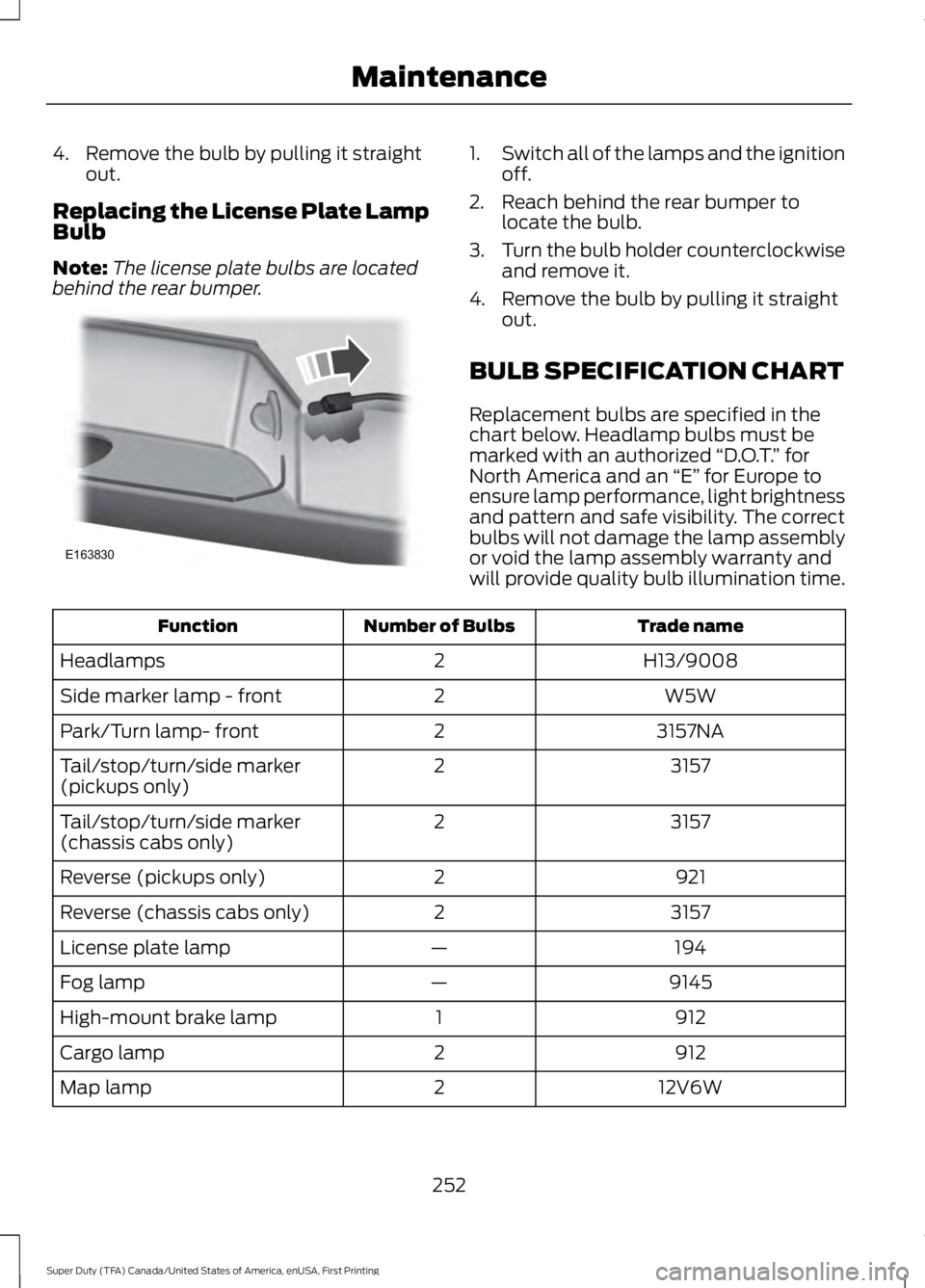
4. Remove the bulb by pulling it straightout.
Replacing the License Plate LampBulb
Note:The license plate bulbs are locatedbehind the rear bumper.
1.Switch all of the lamps and the ignitionoff.
2. Reach behind the rear bumper tolocate the bulb.
3.Turn the bulb holder counterclockwiseand remove it.
4. Remove the bulb by pulling it straightout.
BULB SPECIFICATION CHART
Replacement bulbs are specified in thechart below. Headlamp bulbs must bemarked with an authorized “D.O.T.” forNorth America and an “E” for Europe toensure lamp performance, light brightnessand pattern and safe visibility. The correctbulbs will not damage the lamp assemblyor void the lamp assembly warranty andwill provide quality bulb illumination time.
Trade nameNumber of BulbsFunction
H13/90082Headlamps
W5W2Side marker lamp - front
3157NA2Park/Turn lamp- front
31572Tail/stop/turn/side marker(pickups only)
31572Tail/stop/turn/side marker(chassis cabs only)
9212Reverse (pickups only)
31572Reverse (chassis cabs only)
194—License plate lamp
9145—Fog lamp
9121High-mount brake lamp
9122Cargo lamp
12V6W2Map lamp
252
Super Duty (TFA) Canada/United States of America, enUSA, First Printing
MaintenanceE163830
Page 256 of 507
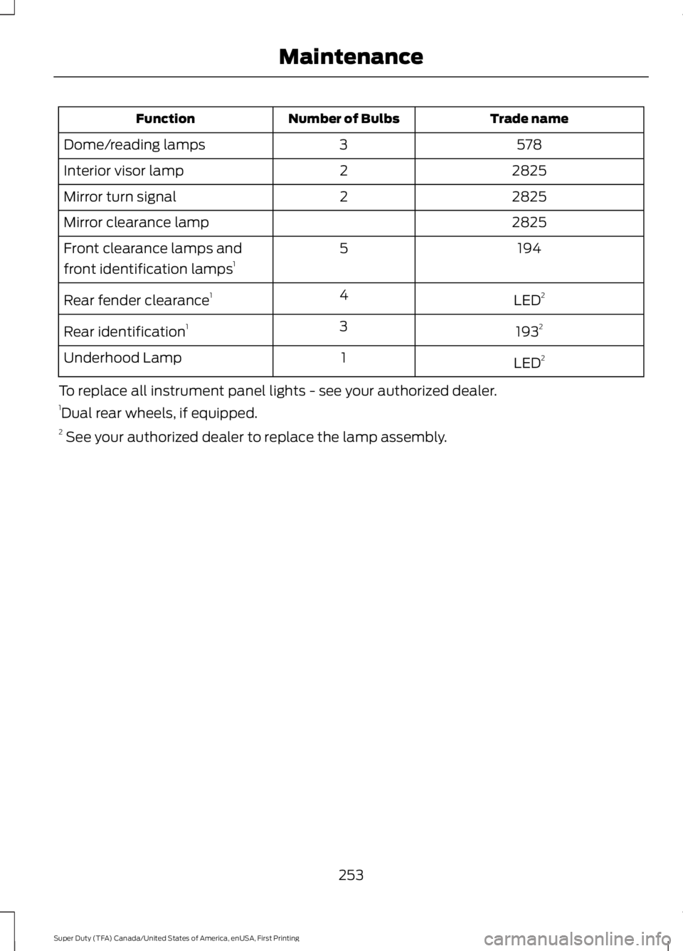
Trade nameNumber of BulbsFunction
5783Dome/reading lamps
28252Interior visor lamp
28252Mirror turn signal
2825Mirror clearance lamp
1945Front clearance lamps and
front identification lamps1
LED24Rear fender clearance1
19323Rear identification1
LED21Underhood Lamp
To replace all instrument panel lights - see your authorized dealer.1Dual rear wheels, if equipped.2 See your authorized dealer to replace the lamp assembly.
253
Super Duty (TFA) Canada/United States of America, enUSA, First Printing
Maintenance
Page 258 of 507
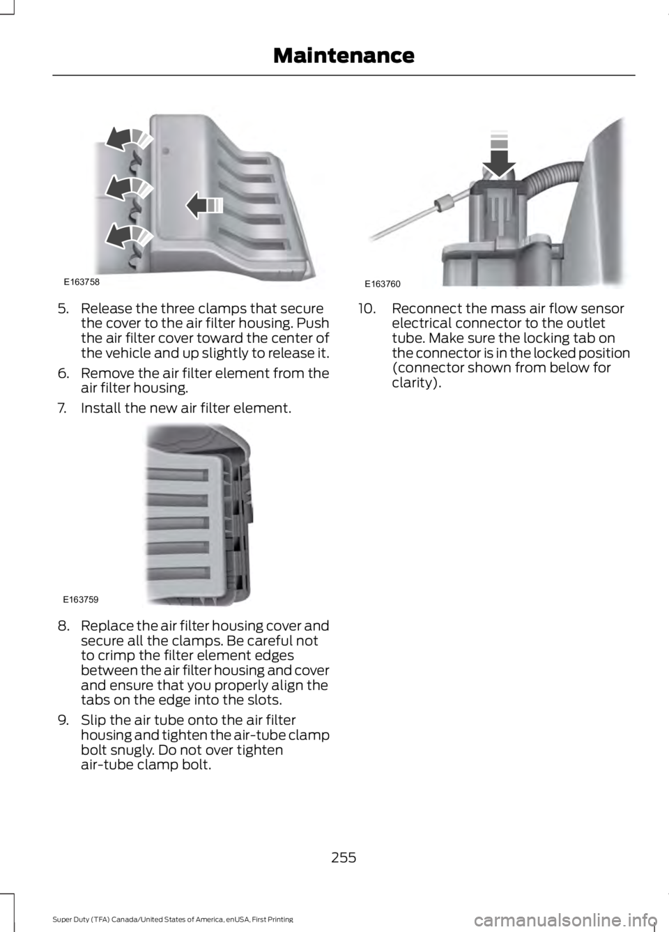
5. Release the three clamps that securethe cover to the air filter housing. Pushthe air filter cover toward the center ofthe vehicle and up slightly to release it.
6.Remove the air filter element from theair filter housing.
7. Install the new air filter element.
8.Replace the air filter housing cover andsecure all the clamps. Be careful notto crimp the filter element edgesbetween the air filter housing and coverand ensure that you properly align thetabs on the edge into the slots.
9. Slip the air tube onto the air filterhousing and tighten the air-tube clampbolt snugly. Do not over tightenair-tube clamp bolt.
10. Reconnect the mass air flow sensorelectrical connector to the outlettube. Make sure the locking tab onthe connector is in the locked position(connector shown from below forclarity).
255
Super Duty (TFA) Canada/United States of America, enUSA, First Printing
MaintenanceE163758 E163759 E163760