Page 24 of 587
INSTRUMENT PANEL
Instrument Panel
1 — Air Vents7 — Upper Switch Bank13 — Lower Switch Bank
2 — Multifunction Lever 8 — Upper Storage Compartment14 — Driver Side Knee Air Bag
3 — Instrument Cluster 9 — Passenger Front Air Bag15 — Ignition
4 — Speed Controls 10 — Air Vents16 — Driver Side Front Air Bag
5 — Windshield Wiper Lever 11 — Lower Storage/Glove Compartment 17 — EVIC Controls
6 — Audio System 12 — Climate Controls18 — Headlight Switch
22 GRAPHICAL TABLE OF CONTENTS
Page 25 of 587
INTERIOR
Interior Features
1 — Power Window Switches
2 — Headlight Switch
3 — Instrument Cluster
4 — Audio System
5 — Glove Compartment6 — Seats
7 — Switch Panel
8 — Transmission Shift Lever (Automatic/Manual Options)
9 — Electronic Speed Controls
10 — EVIC Controls
3
GRAPHICAL TABLE OF CONTENTS 23
Page 164 of 587
The display shows the following information, if
equipped:
•Zone (1)
– Date (Centered)
– Compass (Centered)
– Time (Centered)
– External Temp. (Centered)
• Zone (2)
– Actual Gear Indication (Centered)
– PRND (Centered)
• Zone (3)
– Date (Centered)
– Compass (Centered)
– Time (Centered)
– External Temp. (Centered) •
Zone (4)
– Audio Info (Centered)
– Title (Centered)
– Title Number (Centered)
• Zone (4A)
– Title (Centered)
– Browsing Arrows (Left)
– Title Number (Right)
• Zone (4B)
– Title (Centered)
• Zone (4C)
– Title (Centered)
– Browsing Arrows (Left)
– Title Number (Right)
162 GETTING TO KNOW YOUR INSTRUMENT CLUSTER
Page 168 of 587
•Drive Mode Selector
– Auto Mode
– Sport Mode
– Traction/All Weather Mode
• Vehicle Info
– Tire Pressure
– Oil Temperature
– Battery Voltage
• Driver Assist
– Lane Departure Warning
• Audio
• Navigation
• Messages
• Settings
– Display – Units
– Clock & Date
– Security
– Safety & Assistance
– Lights
– Doors & Locks
Trip
This EVIC menu item allows you to view and select
information about the
�Trip computer�:
• Speedometer
– View and change the speedometer scale from MPH to km/h (km/h to MPH).
• Instantaneous info
– View and change the distance (miles or km)
– View and change the instantaneous consumption (mpg, or l/ 100km or km/l)
166 GETTING TO KNOW YOUR INSTRUMENT CLUSTER
Page 170 of 587

Vehicle Info
Push and release the UP or DOWN arrow button until
�Vehicle Info�is highlighted in the EVIC. Push and
release the RIGHT arrow button and Coolant Temp will
be displayed. Push the RIGHT or LEFT arrow button to
scroll through the following information displays:
• Tire pressure
– View the information relating to the TPMS system (if equipped).
• Oil Temperature
– View the engine oil temperature.
• Battery Voltage
– View the voltage value (state of charge) of the battery.
Driver Assist
This menu item allows you to change the settings ( �No-
tice LaneSense� and�Intensity LaneSense�) relating to the
LaneSense system (if equipped).
• Notice LaneSense
• By selecting this function, you can select the �readi-
ness� of LaneSense, choosing between the options
�Near,�� Medium,� or�Far.�
• Intensity LaneSense
• Using this function, you can select the force applied to
the steering wheel to keep the car in the roadway
through the electrical drive system due to LaneSense.
Audio
This menu item allows you to view the instrument
cluster display and the information present on the dis-
play of the Uconnect system.
168 GETTING TO KNOW YOUR INSTRUMENT CLUSTER
Page 330 of 587

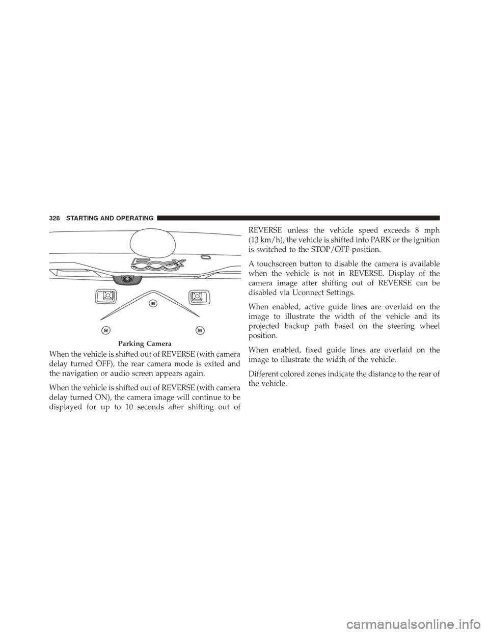
When the vehicle is shifted out of REVERSE (with camera
delay turned OFF), the rear camera mode is exited and
the navigation or audio screen appears again.
When the vehicle is shifted out of REVERSE (with camera
delay turned ON), the camera image will continue to be
displayed for up to 10 seconds after shifting out ofREVERSE unless the vehicle speed exceeds 8 mph
(13 km/h), the vehicle is shifted into PARK or the ignition
is switched to the STOP/OFF position.
A touchscreen button to disable the camera is available
when the vehicle is not in REVERSE. Display of the
camera image after shifting out of REVERSE can be
disabled via Uconnect Settings.
When enabled, active guide lines are overlaid on the
image to illustrate the width of the vehicle and its
projected backup path based on the steering wheel
position.
When enabled, fixed guide lines are overlaid on the
image to illustrate the width of the vehicle.
Different colored zones indicate the distance to the rear of
the vehicle.
Parking Camera
328 STARTING AND OPERATING
Page 391 of 587
Push on the left side of the access door to unhinge and
remove.
CavityMini Fuse Description
F2 20 Amp Yellow Audio System
F3 20 Amp Yellow Electric Sunroof
F5 30 Amp Green Power Seat (driver side)
Rear Cargo Fuse Cavities8
IN CASE OF EMERGENCY 389
Page 515 of 587
MULTIMEDIA
CONTENTS
�UCONNECT SETTINGS ..................515
▫ Buttons On The Faceplate ................516
▫ Buttons On The Touchscreen ..............517
▫ Customer Programmable Features — Uconnect 5.0
Settings ........................... .517
▫ Customer Programmable Features — Uconnect
6.5AN Settings ...................... .531
� UCONNECT RADIOS ...................548
� USB/MEDIA PLAYER CONTROL — IF
EQUIPPED .......................... .548
� STEERING WHEEL AUDIO CONTROLS ......549▫
Radio Operation ..................... .550
▫ Media Mode ........................ .551
� RADIO OPERATION AND MOBILE DEVICES . .551
▫ Regulatory And Safety Information .........551
� UCONNECT VOICE RECOGNITION
QUICK TIPS ......................... .553
▫ Introducing Uconnect ...................553
▫ Get Started ......................... .554
▫ Basic Voice Commands ..................556
▫ Radio ............................. .557
11