Page 112 of 587

The Manual Climate Controls consist of a series of rotary
dials with inner push buttons.
1. Blower Control
Rotate this control to regulate the amount of air forced
through the ventilation system in any mode. The blower
speed increases as you move the control clockwise from
the “0” (OFF) position.
2. Temperature Control
Rotate this control to regulate the temperature of the air
inside the passenger compartment. Rotating the dial
counter-clockwise into the blue area of the scale indicates
cooler temperatures, while rotating clockwise into the red
area indicates warmer temperatures. Rotating the Tem-
perature Control all the way counter-clockwise results in
turning on the MAX A/C feature.3. Mode Control
Rotate this control to change the system between Modes
(Panel, Bi-Level, Floor, Mix, Defrost).
•Panel
Air is directed through the outlets in the
instrument panel. These outlets can be ad-
justed to direct airflow.
NOTE: The center instrument panel outlets can be ad-
justed so that they are directed toward the rear seat
passengers for maximum airflow to the rear.
•Bi-Level
Air is directed through the panel and floor
outlets.
• Floor
Air is directed through the floor outlets with a
small amount flowing through the defrost and
side window demister outlets.
110 GETTING TO KNOW YOUR VEHICLE
Page 187 of 587
Front Fog Lights•What Does It Mean
The light comes on by activating the fog
lights.
Left/Right Turn Signals •What Does It Mean
The indicator lights flash when the multi-
function lever is moved up/down to
show proper operation of the front and
rear turn signal lights (down (left signal)
up (right signal). It is also used along with
the right arrow when the Hazard Warning
flashers are turned on. Headlights On
•What Does It Mean
The indicator light comes on by turning on
the headlights.
Cruise SET Indicator — If Equipped •What Does It Mean
This light will turn on when the electronic
speed control is SET.
Glow Plug Icon •What Does It Mean
This icon blinking indicates that the engine
cranking is inhibited in order to prevent
possible engine damage while starting at
low temperatures.
Green
Warning Light
Green
Direction
Indicators
Blue
Warning Light
5
GETTING TO KNOW YOUR INSTRUMENT CLUSTER 185
Page 384 of 587
Cavity Maxi FuseCartage FuseMini FuseDescription
F01 70 Amp Tan ––Module Body Com-
puter
F02 60 Amp Blue ––Module Body Com-
puter, Rear Distribution
Units
F03 – 20 Amp Blue–Controller Power Sup-
ply Body Computer
F04 – 30 Amp Pink–Brake Control Electron-
ics Module
F05 70 Amp Tan ––Electric Power-Assisted
Steering
F06 20 Amp Yellow – –Engine Cooling fan
F07 50 Amp Red ––Engine Cooling fan
F08 – 30 Amp Pink–Automatic Transmis-
sion, GSM
F09 – –5 Amp TanControl Module Engine
382 IN CASE OF EMERGENCY
Page 385 of 587
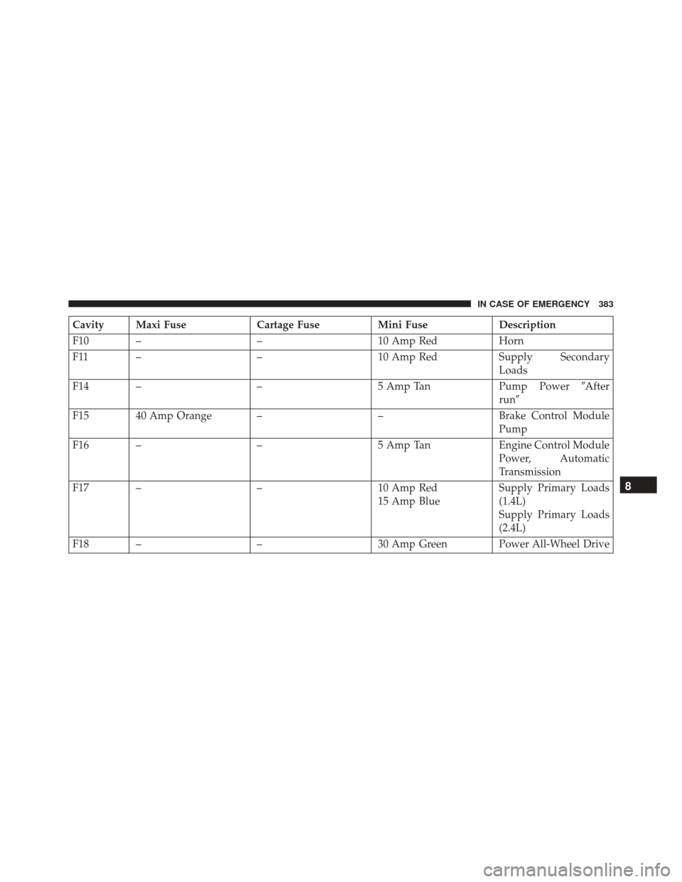
Cavity Maxi FuseCartage FuseMini FuseDescription
F10 – –10 Amp RedHorn
F11 – –10 Amp RedSupply Secondary
Loads
F14 – –5 Amp TanPump Power�After
run �
F15 40 Amp Orange – –Brake Control Module
Pump
F16 – –5 Amp TanEngine Control Module
Power, Automatic
Transmission
F17 – –10 Amp Red
15 Amp Blue Supply Primary Loads
(1.4L)
Supply Primary Loads
(2.4L)
F18 – –30 Amp Green Power All-Wheel Drive
8
IN CASE OF EMERGENCY 383
Page 386 of 587
Cavity Maxi FuseCartage FuseMini FuseDescription
F19 – –7.5 Amp Brown Air Conditioner Com-
pressor
F20 – –5 Amp TanElectronic Power Four-
Wheel Drive
F21 – –15 Amp BlueFuel Pump
F22 – –20 Amp Yelow Power Control Module
Engine
F23 – –20 Amp Yellow (Cus-
tomer Installed) Power Outlet (Battery
Powered)
F24 – –15 Amp BlueElectronic Unit Supply
Automatic Transmis-
sion
F30 – –30 Amp Green Heated Windshield – If
Equipped
F83 – 40 Amp Green – Air Conditioning Fan
384 IN CASE OF EMERGENCY
Page 389 of 587
Cavity Mini FuseDescription
F31 7.5 Amp Brown Fan Air Conditioning, Power Socket
F33 20 Amp Yellow Power Window Front (Passenger Side)
F34 20 Amp Yellow Power Window Front (Drivers Side)
F36 15 Amp Blue Supply Uconnect System, Air Conditioning, USB Port, Rear lateral ceiling light in case of open roof, EOBD port
F37 10 Amp Red System Power Forward Collision Warning Plus, All Wheel Drive (AWD), IPC, Central stack switches, Brake Pedal Switch (NC)
F38 20 Amp Yellow Central Locking
F42 7.5 Amp Brown BSM - Brake Control Module, EPS - Electric Power-Assisted Steering
F43 20 Amp Yellow Bi-directional Pump Washer
F47 20 Amp Yellow Power Rear Window (Driver Side)
F48 20 Amp Yellow Power Rear Window (Passenger Side)
F49 7.5 Amp Brown Supply ParkSense, Spot Lights Front Dome, Internal Electocromic Mirror, Heated Front Seats
F50 7.5 Amp Brown Supply Air Bag
8
IN CASE OF EMERGENCY 387
Page 519 of 587

Buttons On The Touchscreen
Buttons on the touchscreen are accessible on the
Uconnect touchscreen.
Customer Programmable Features — Uconnect
5.0 Settings
Push the Settingsbutton on the faceplate, to display
the settings menu screen. In this mode the Uconnect
system allows you to access programmable features
that may be equipped such as Display, Units, Voice,
Clock & Date, Safety/Assistance, Lights, Doors &
Locks, Engine Off Options, Audio, Phone/Bluetooth,
Radio Setup, Restore Settings and Clear Personal Data.
NOTE: Only one touchscreen area may be selected at a
time.
When making a selection, press the button on the touch-
screen to enter the desired mode. Once in the desired
mode, press and release the preferred setting and make your selection. Once the setting is complete, either press
the Back Arrow button on the touchscreen or the Back
button on the faceplate to return to the previous menu or
press the “X” button on the touchscreen to close out of
the settings screen. Pressing the Up or Down Arrow
buttons on the right side of the screen will allow you to
toggle up or down through the available settings.
NOTE:
All settings should be changed with the ignition
in the “ AVV/START ” position.
Display
After pressing the “Display” button on the touchscreen
the following settings will be available.
• Display Mode
When in this display you may select the “Auto” or
“Manual” display settings. To change Mode status, press
and release the “Auto” or “Manual” button on the
touchscreen.
11
MULTIMEDIA 517
Page 531 of 587

•Loudness — If Equipped
Loudness improves sound quality at lower volumes. To
make your selection, press the “Loudness” button on the
touchscreen, then choose “Yes” or “No.” The button will
highlight indicating that the setting has been selected.
• AUX Volume Offset — If Equipped
This feature provides the ability to tune the audio level
for portable devices connected through the AUX input.
To make your selection, press the “AUX Volume Offset”
button on the touchscreen, select “On” or “Off”.
• Auto-On Radio
The Radio automatically turns on when vehicle is in run
or will recall whether it was on or off at last ignition off.
To make your selection, press the “Loudness” button on
the touchscreen, select “On,” “Off” or “Recall Last”.Phone/Bluetooth
After pressing the “Phone/Bluetooth” button on the
touchscreen the following settings will be available:
• Paired Phones
This feature shows which phones are paired to the
Phone/Bluetooth system. For further information, refer
to the Uconnect Supplement Manual.
SiriusXM Setup — If Equipped
After pressing the “SiriusXM Setup” button on the touch-
screen, the following settings will be available:
• Channel Skip
SiriusXM can be programmed to designate a group of
channels that are the most desirable to listen to or to
exclude undesirable channels while scanning. To make
your selection, press the “Channel Skip” button on the
touchscreen, select the channels you would like to skip.
11
MULTIMEDIA 529


F34 20 Amp Yellow Power Window Front (Drivers Side)
F36 15 Amp Bl")