Page 358 of 587
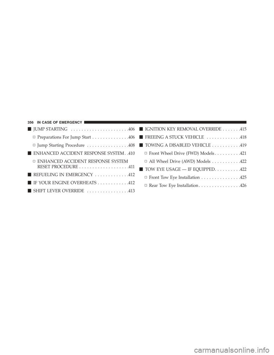
�JUMP STARTING ..................... .406
▫ Preparations For Jump Start ..............406
▫ Jump Starting Procedure ................408
� ENHANCED ACCIDENT RESPONSE SYSTEM . .410
▫ ENHANCED ACCIDENT RESPONSE SYSTEM
RESET PROCEDURE ...................411
� REFUELING IN EMERGENCY .............412
� IF YOUR ENGINE OVERHEATS ............412
� SHIFT LEVER OVERRIDE ................413�
IGNITION KEY REMOVAL OVERRIDE .......415
� FREEING A STUCK VEHICLE .............418
� TOWING A DISABLED VEHICLE ...........419
▫ Front Wheel Drive (FWD) Models ..........421
▫ All Wheel Drive (AWD) Models ...........422
� TOW EYE USAGE — IF EQUIPPED ..........422
▫ Front Tow Eye Installation ...............425
▫ Rear Tow Eye Installation ................426
356 IN CASE OF EMERGENCY
Page 362 of 587
Replacing Exterior Bulbs
HeadlampsHi/Lo Beam Light Halogen
To replace the bulbs proceed as follows:
1. Open the engine compartment and remove the head-
lamp bulb cap.
Front Lamps1 — Headlamps
2 — Daytime Running Lamps
3 — Directional Indicators
4 — Fog Lamps — If Equipped
Headlamp Bulb Cap
360 IN CASE OF EMERGENCY
Page 364 of 587
WARNING!
Carry out the operation of replacing lamps only with
the engine off. Also make sure that the engine is cold,
to avoid the danger of burns.Position Lights/Daytime Running Lights/Fog Lights
To replace the bulbs proceed as follows:
1. Turn the front wheels completely.
2. Use a suitable tool to remove the access door.
Headlamp Bulb Connector
362 IN CASE OF EMERGENCY
Page 380 of 587
WARNING!(Continued)
•Before replacing a fuse, make sure that the ignition
is off and that all the other services are switched off
and/or disengaged.
• If the replaced fuse blows again, contact an autho-
rized dealer.
• If a general protection fuse for safety systems (air
bag system, braking system), power unit systems
(engine system, gearbox system) or steering system
blows, contact an authorized dealer.
General Information
The fuses protect electrical systems against excessive current.
When a device does not work you must check the
electrical circuit inside the fuse for a break/melt.
Also please be aware that when using power outlets for
extended periods of time with the engine off may result
in vehicle battery discharge.
Blade Fuses
1 — Electrical Circuit
2 — Blade Fuse With Good Electrical Circuit
3 — Blade Fuse With Bad Electrical Circuit
378 IN CASE OF EMERGENCY
Page 381 of 587
Fuse Removal
To replace a fuse use the extractor attached to the fuse
cover (located on the inside of the engine compartment
fuse cover.Access To The Fuses
The fuses are grouped into four controllers located in the
engine compartment, under the instrument panel and on
the inside of the left side cargo trim panel.
Engine Compartment Fuses/Distribution Unit
The engine compartment fuse panel is located on the left
side of the engine compartment.
Fuse Extractor Location
8
IN CASE OF EMERGENCY 379
Page 382 of 587
Engine Compartment Fuse CavitiesFuse Panel And Cover Location
1 — Mounting Screw
2 — Fuse Cover
380 IN CASE OF EMERGENCY
Page 384 of 587
Cavity Maxi FuseCartage FuseMini FuseDescription
F01 70 Amp Tan ––Module Body Com-
puter
F02 60 Amp Blue ––Module Body Com-
puter, Rear Distribution
Units
F03 – 20 Amp Blue–Controller Power Sup-
ply Body Computer
F04 – 30 Amp Pink–Brake Control Electron-
ics Module
F05 70 Amp Tan ––Electric Power-Assisted
Steering
F06 20 Amp Yellow – –Engine Cooling fan
F07 50 Amp Red ––Engine Cooling fan
F08 – 30 Amp Pink–Automatic Transmis-
sion, GSM
F09 – –5 Amp TanControl Module Engine
382 IN CASE OF EMERGENCY
Page 385 of 587
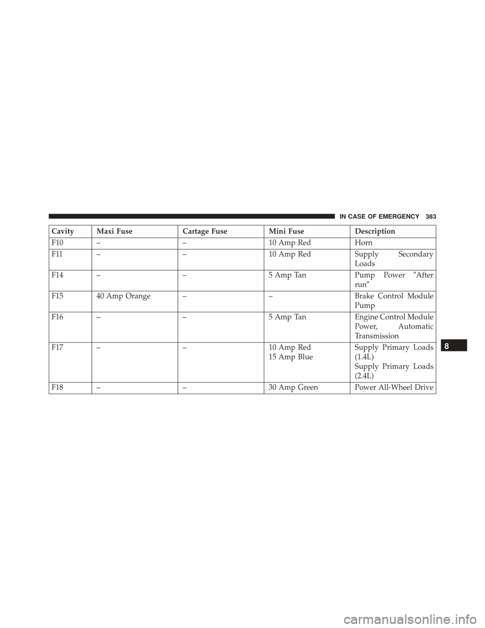
Cavity Maxi FuseCartage FuseMini FuseDescription
F10 – –10 Amp RedHorn
F11 – –10 Amp RedSupply Secondary
Loads
F14 – –5 Amp TanPump Power�After
run �
F15 40 Amp Orange – –Brake Control Module
Pump
F16 – –5 Amp TanEngine Control Module
Power, Automatic
Transmission
F17 – –10 Amp Red
15 Amp Blue Supply Primary Loads
(1.4L)
Supply Primary Loads
(2.4L)
F18 – –30 Amp Green Power All-Wheel Drive
8
IN CASE OF EMERGENCY 383


•Before replacing a fuse, make sure that the ignition
is off and that all the other services are switched off
and/or disengaged.
• If the replaced fuse blows again, contact an")