Page 386 of 587
Cavity Maxi FuseCartage FuseMini FuseDescription
F19 – –7.5 Amp Brown Air Conditioner Com-
pressor
F20 – –5 Amp TanElectronic Power Four-
Wheel Drive
F21 – –15 Amp BlueFuel Pump
F22 – –20 Amp Yelow Power Control Module
Engine
F23 – –20 Amp Yellow (Cus-
tomer Installed) Power Outlet (Battery
Powered)
F24 – –15 Amp BlueElectronic Unit Supply
Automatic Transmis-
sion
F30 – –30 Amp Green Heated Windshield – If
Equipped
F83 – 40 Amp Green – Air Conditioning Fan
384 IN CASE OF EMERGENCY
Page 392 of 587
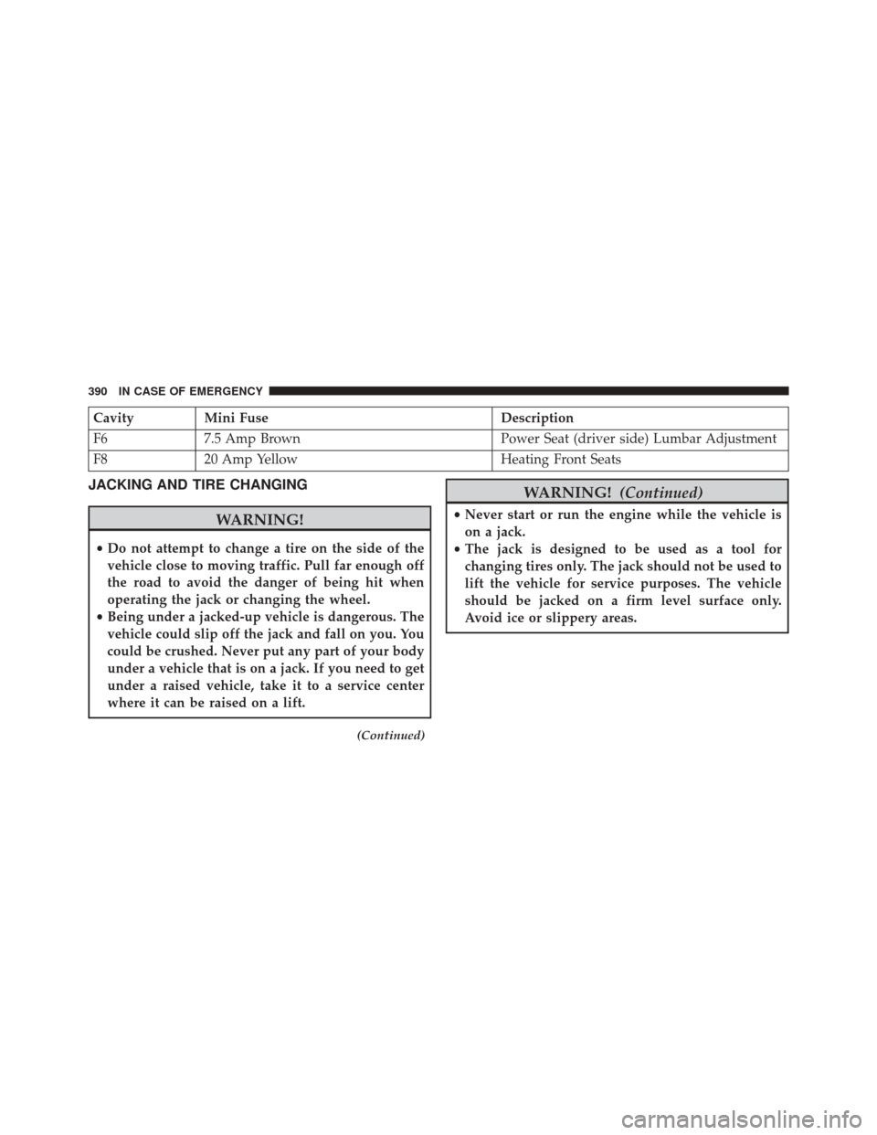
CavityMini Fuse Description
F6 7.5 Amp Brown Power Seat (driver side) Lumbar Adjustment
F8 20 Amp Yellow Heating Front Seats
JACKING AND TIRE CHANGING
WARNING!
•Do not attempt to change a tire on the side of the
vehicle close to moving traffic. Pull far enough off
the road to avoid the danger of being hit when
operating the jack or changing the wheel.
• Being under a jacked-up vehicle is dangerous. The
vehicle could slip off the jack and fall on you. You
could be crushed. Never put any part of your body
under a vehicle that is on a jack. If you need to get
under a raised vehicle, take it to a service center
where it can be raised on a lift.
(Continued)
WARNING! (Continued)
•Never start or run the engine while the vehicle is
on a jack.
• The jack is designed to be used as a tool for
changing tires only. The jack should not be used to
lift the vehicle for service purposes. The vehicle
should be jacked on a firm level surface only.
Avoid ice or slippery areas.
390 IN CASE OF EMERGENCY
Page 396 of 587
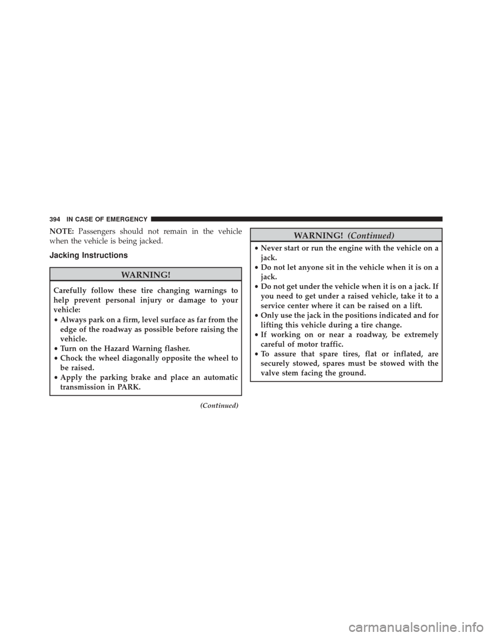
NOTE:Passengers should not remain in the vehicle
when the vehicle is being jacked.
Jacking Instructions
WARNING!
Carefully follow these tire changing warnings to
help prevent personal injury or damage to your
vehicle:
• Always park on a firm, level surface as far from the
edge of the roadway as possible before raising the
vehicle.
• Turn on the Hazard Warning flasher.
• Chock the wheel diagonally opposite the wheel to
be raised.
• Apply the parking brake and place an automatic
transmission in PARK.
(Continued)
WARNING! (Continued)
•Never start or run the engine with the vehicle on a
jack.
• Do not let anyone sit in the vehicle when it is on a
jack.
• Do not get under the vehicle when it is on a jack. If
you need to get under a raised vehicle, take it to a
service center where it can be raised on a lift.
• Only use the jack in the positions indicated and for
lifting this vehicle during a tire change.
• If working on or near a roadway, be extremely
careful of motor traffic.
• To assure that spare tires, flat or inflated, are
securely stowed, spares must be stowed with the
valve stem facing the ground.
394 IN CASE OF EMERGENCY
Page 406 of 587
WARNING!(Continued)
reach of children. If swallowed, rinse mouth imme-
diately with plenty of water and drink plenty of
water. Do not induce vomiting! Consult a physician
immediately.
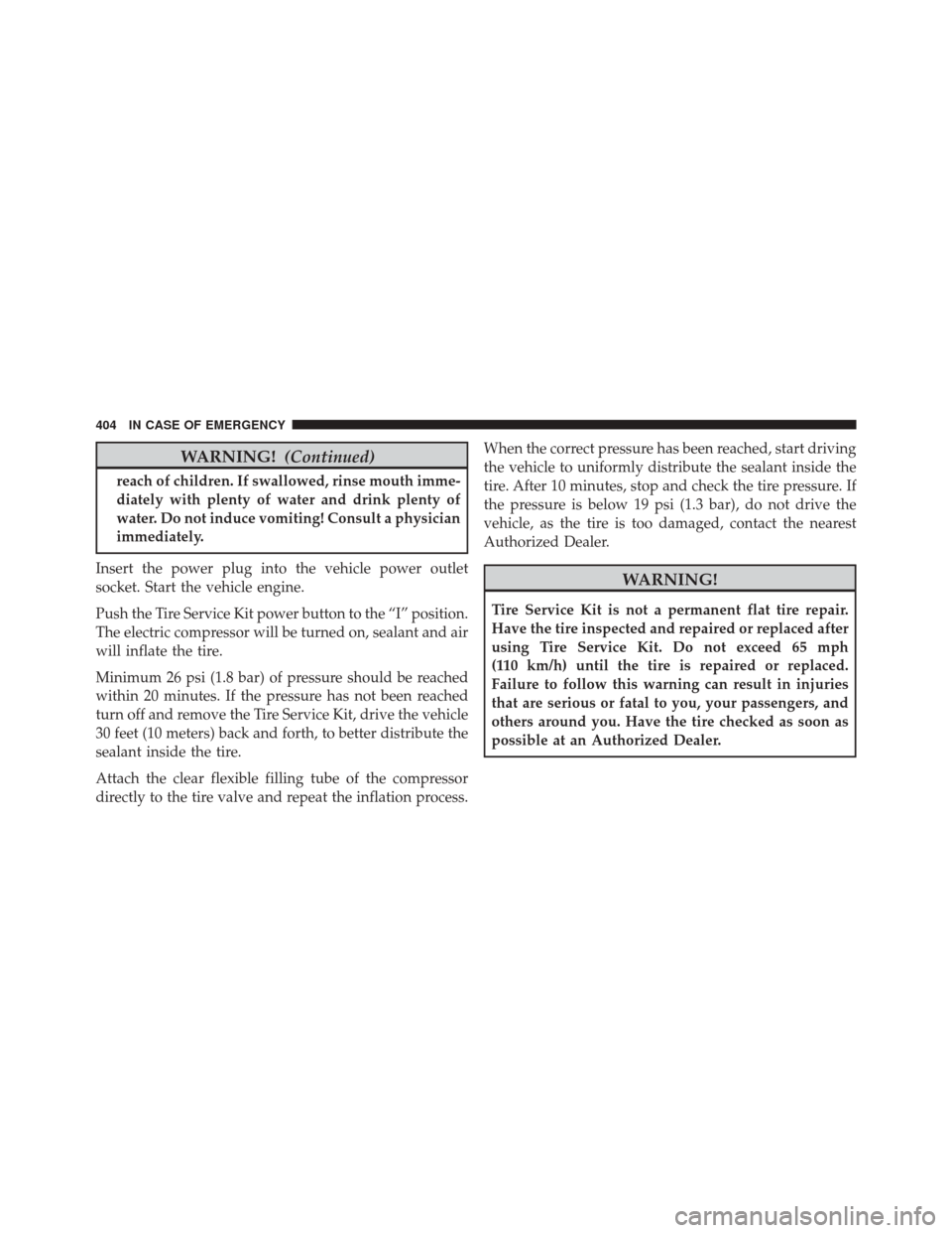
Insert the power plug into the vehicle power outlet
socket. Start the vehicle engine.
Push the Tire Service Kit power button to the “I” position.
The electric compressor will be turned on, sealant and air
will inflate the tire.
Minimum 26 psi (1.8 bar) of pressure should be reached
within 20 minutes. If the pressure has not been reached
turn off and remove the Tire Service Kit, drive the vehicle
30 feet (10 meters) back and forth, to better distribute the
sealant inside the tire.
Attach the clear flexible filling tube of the compressor
directly to the tire valve and repeat the inflation process. When the correct pressure has been reached, start driving
the vehicle to uniformly distribute the sealant inside the
tire. After 10 minutes, stop and check the tire pressure. If
the pressure is below 19 psi (1.3 bar), do not drive the
vehicle, as the tire is too damaged, contact the nearest
Authorized Dealer.
WARNING!
Tire Service Kit is not a permanent flat tire repair.
Have the tire inspected and repaired or replaced after
using Tire Service Kit. Do not exceed 65 mph
(110 km/h) until the tire is repaired or replaced.
Failure to follow this warning can result in injuries
that are serious or fatal to you, your passengers, and
others around you. Have the tire checked as soon as
possible at an Authorized Dealer.
404 IN CASE OF EMERGENCY
Page 408 of 587
JUMP STARTING
If your vehicle has a discharged battery it can be jump-
started using a set of jumper cables and a battery in
another vehicle or by using a portable battery booster
pack. Jump starting can be dangerous if done improperly
so please follow the procedures in this section carefully.
NOTE:When using a portable battery booster pack
follow the manufacturer ’s operating instructions and
precautions.
CAUTION!
Do not use a portable battery booster pack or any
other booster source with a system voltage greater
than 12 Volts or damage to the battery, starter motor,
alternator or electrical system may occur.
WARNING!
Do not attempt jump-starting if the battery is frozen.
It could rupture or explode and cause personal injury.
Preparations For Jump Start
The battery in your vehicle is located in the front of the
engine compartment, behind the left headlight assembly.
406 IN CASE OF EMERGENCY
Page 411 of 587
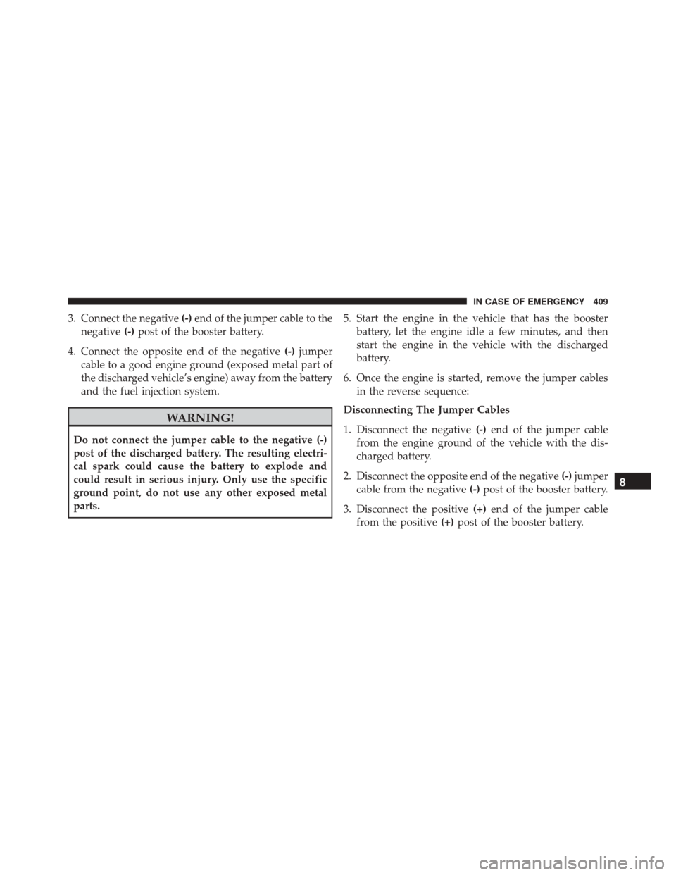
3. Connect the negative(-)end of the jumper cable to the
negative (-)post of the booster battery.
4. Connect the opposite end of the negative (-)jumper
cable to a good engine ground (exposed metal part of
the discharged vehicle’s engine) away from the battery
and the fuel injection system.
WARNING!
Do not connect the jumper cable to the negative (-)
post of the discharged battery. The resulting electri-
cal spark could cause the battery to explode and
could result in serious injury. Only use the specific
ground point, do not use any other exposed metal
parts. 5. Start the engine in the vehicle that has the booster
battery, let the engine idle a few minutes, and then
start the engine in the vehicle with the discharged
battery.
6. Once the engine is started, remove the jumper cables in the reverse sequence:
Disconnecting The Jumper Cables
1. Disconnect the negative (-)end of the jumper cable
from the engine ground of the vehicle with the dis-
charged battery.
2. Disconnect the opposite end of the negative (-)jumper
cable from the negative (-)post of the booster battery.
3. Disconnect the positive (+)end of the jumper cable
from the positive (+)post of the booster battery.
8
IN CASE OF EMERGENCY 409
Page 412 of 587
4. Disconnect the opposite end of the positive(+)jumper
cable from the positive (+)post of the vehicle with the
discharged battery.
If frequent jump starting is required to start your vehicle
you should have the battery and charging system in-
spected at your authorized dealer.
CAUTION!
Accessories plugged into the vehicle power outlets
draw power from the vehicle’s battery, even when not
in use (i.e., cellular devices, etc.). Eventually, if
plugged in long enough without engine operation,
the vehicle’s battery will discharge sufficiently to
degrade battery life and/or prevent the engine from
starting.
ENHANCED ACCIDENT RESPONSE SYSTEM
In the event of an impact, if the communication network
remains intact, and the power remains intact, depending
on the nature of the event, the ORC will determine
whether to have the Enhanced Accident Response Sys-
tem perform the following functions:
• Cut off fuel to the engine.
• Flash hazard lights as long as the battery has power or
until the hazard light button is pressed. The hazard
lights can be deactivated by pressing the hazard light
button.
• Turn on the interior lights, which remain on as long as
the battery has power or for 15 minutes from the
intervention of the Enhanced Accident Response Sys-
tem.
• Unlock the power door locks.
410 IN CASE OF EMERGENCY
Page 413 of 587
•Turn off the Fuel Pump Heater.
• Turn off the HVAC Blower Motor.
• Close the HVAC Circulation Door.
ENHANCED ACCIDENT RESPONSE SYSTEM
RESET PROCEDURE
After the event occurs, when the system is active, a
message regarding fuel cutoff is displayed. Turn the
ignition switch from ignition AVV/START or MAR/
ACC/ON/RUN to ignition STOP/OFF/LOCK. Care-
fully check the vehicle for fuel leaks in the engine
compartment and on the ground near the engine com-
partment and fuel tank before resetting the system and
starting the engine.
Depending on the nature of the event the left and right
turn signal lights, located in the instrument panel, may
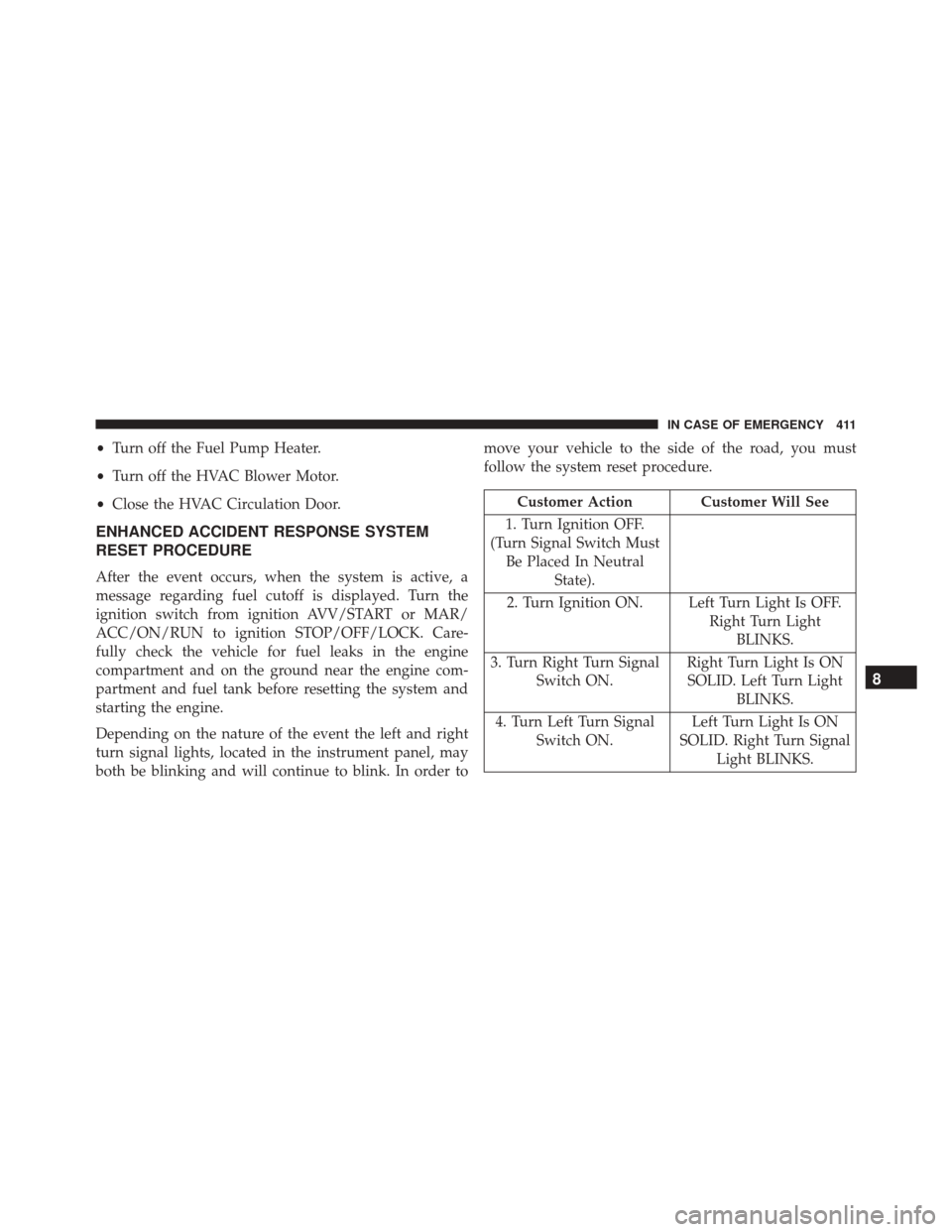
both be blinking and will continue to blink. In order to move your vehicle to the side of the road, you must
follow the system reset procedure.
Customer Action Customer Will See
1. Turn Ignition OFF.
(Turn Signal Switch Must Be Placed In Neutral State).
2. Turn Ignition ON. Left Turn Light Is OFF. Right Turn LightBLINKS.
3. Turn Right Turn Signal Switch ON. Right Turn Light Is ON
SOLID. Left Turn Light BLINKS.
4. Turn Left Turn Signal Switch ON. Left Turn Light Is ON
SOLID. Right Turn Signal Light BLINKS.
8
IN CASE OF EMERGENCY 411