Page 127 of 661
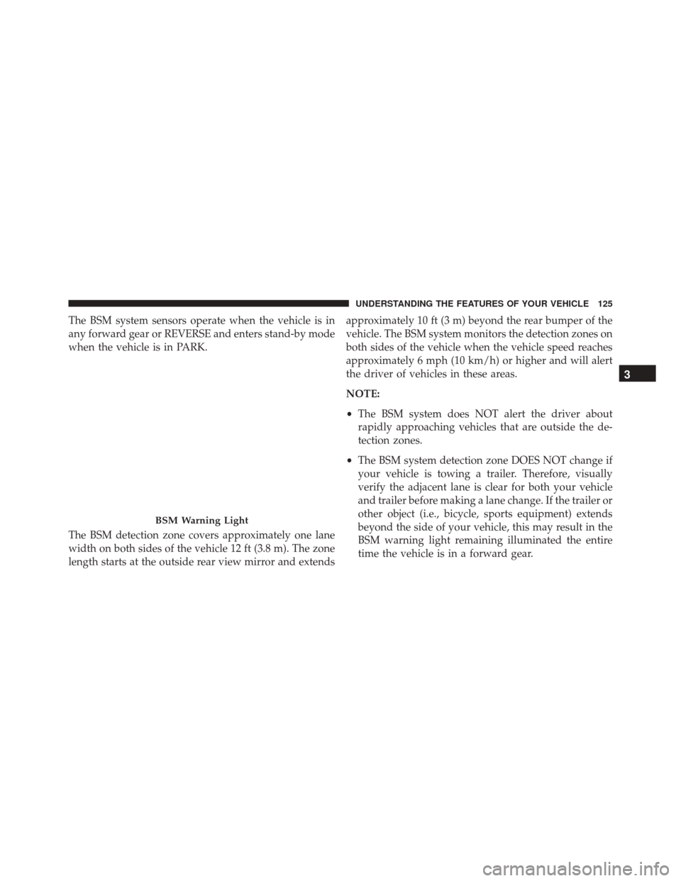
The BSM system sensors operate when the vehicle is in
any forward gear or REVERSE and enters stand-by mode
when the vehicle is in PARK.
The BSM detection zone covers approximately one lane
width on both sides of the vehicle 12 ft (3.8 m). The zone
length starts at the outside rear view mirror and extendsapproximately 10 ft (3 m) beyond the rear bumper of the
vehicle. The BSM system monitors the detection zones on
both sides of the vehicle when the vehicle speed reaches
approximately 6 mph (10 km/h) or higher and will alert
the driver of vehicles in these areas.
NOTE:
•
The BSM system does NOT alert the driver about
rapidly approaching vehicles that are outside the de-
tection zones.
• The BSM system detection zone DOES NOT change if
your vehicle is towing a trailer. Therefore, visually
verify the adjacent lane is clear for both your vehicle
and trailer before making a lane change. If the trailer or
other object (i.e., bicycle, sports equipment) extends
beyond the side of your vehicle, this may result in the
BSM warning light remaining illuminated the entire
time the vehicle is in a forward gear.
BSM Warning Light
3
UNDERSTANDING THE FEATURES OF YOUR VEHICLE 125
Page 184 of 661
WARNING!(Continued)
•The ACC system:
• Does not react to pedestrians, oncoming vehicles,
and stationary objects (e.g., a stopped vehicle in a
traffic jam or a disabled vehicle).
• Cannot take street, traffic, and weather condi-
tions into account, and may be limited upon
adverse sight distance conditions.
• Does not always fully recognize complex driving
conditions, which can result in wrong or missing
distance warnings.
• Will bring the vehicle to a complete stop while
following a target vehicle and hold the vehicle
for 2 seconds in the stop position. If the target
vehicle does not start moving within two seconds
the ACC system will display a message that the
system will release the brakes and that the
(Continued)
WARNING! (Continued)
brakes must be applied manually. An audible
chime will sound when the brakes are released.
You should switch off the ACC system:
• When driving in fog, heavy rain, heavy snow, sleet,
heavy traffic, and complex driving situations (i.e.,
in highway construction zones).
• When entering a turn lane or highway off ramp;
when driving on roads that are winding, icy, snow-
covered, slippery, or have steep uphill or downhill
slopes.
• When towing a trailer up or down steep slopes.
• When circumstances do not allow safe driving at a
constant speed.
Adaptive Cruise Control (ACC) Operation
The speed control buttons (located on the right side of the
steering wheel) operates the ACC system.
182 UNDERSTANDING THE FEATURES OF YOUR VEHICLE
Page 201 of 661
Precautions While Driving With ACC
In certain driving situations, ACC may have detection
issues. In these cases, ACC may brake late or unexpect-
edly. The driver needs to stay alert and may need to
intervene.
Towing A Trailer
Towing a trailer is not advised when using ACC.
Offset Driving
ACC may not detect a vehicle in the same lane that is
offset from your direct line of travel, or a vehicle merging
in from a side lane. There may not be sufficient distance
to the vehicle ahead. The offset vehicle may move in and
out of the line of travel, which can cause your vehicle to
brake or accelerate unexpectedly.
Turns And Bends
When driving on a curve with ACC engaged, the system
may decrease the vehicle speed and acceleration for
stability reasons, with no target vehicle detected. Once
Offset Driving Condition Example
3
UNDERSTANDING THE FEATURES OF YOUR VEHICLE 199
Page 264 of 661
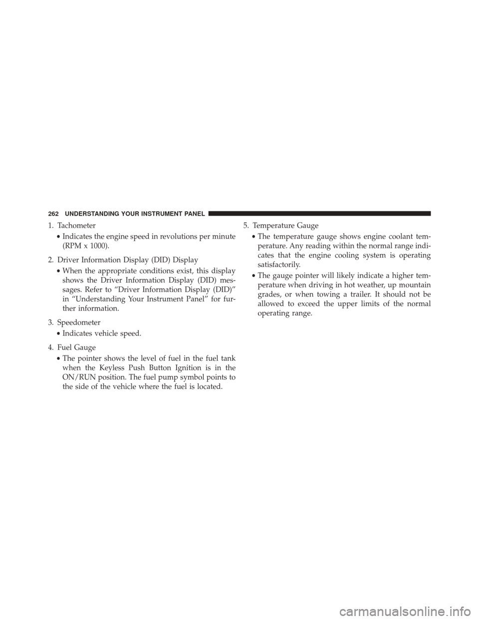
1. Tachometer•Indicates the engine speed in revolutions per minute
(RPM x 1000).
2. Driver Information Display (DID) Display •When the appropriate conditions exist, this display
shows the Driver Information Display (DID) mes-
sages. Refer to “Driver Information Display (DID)”
in “Understanding Your Instrument Panel” for fur-
ther information.
3. Speedometer •Indicates vehicle speed.
4. Fuel Gauge •The pointer shows the level of fuel in the fuel tank
when the Keyless Push Button Ignition is in the
ON/RUN position. The fuel pump symbol points to
the side of the vehicle where the fuel is located. 5. Temperature Gauge
•The temperature gauge shows engine coolant tem-
perature. Any reading within the normal range indi-
cates that the engine cooling system is operating
satisfactorily.
• The gauge pointer will likely indicate a higher tem-
perature when driving in hot weather, up mountain
grades, or when towing a trailer. It should not be
allowed to exceed the upper limits of the normal
operating range.
262 UNDERSTANDING YOUR INSTRUMENT PANEL
Page 267 of 661
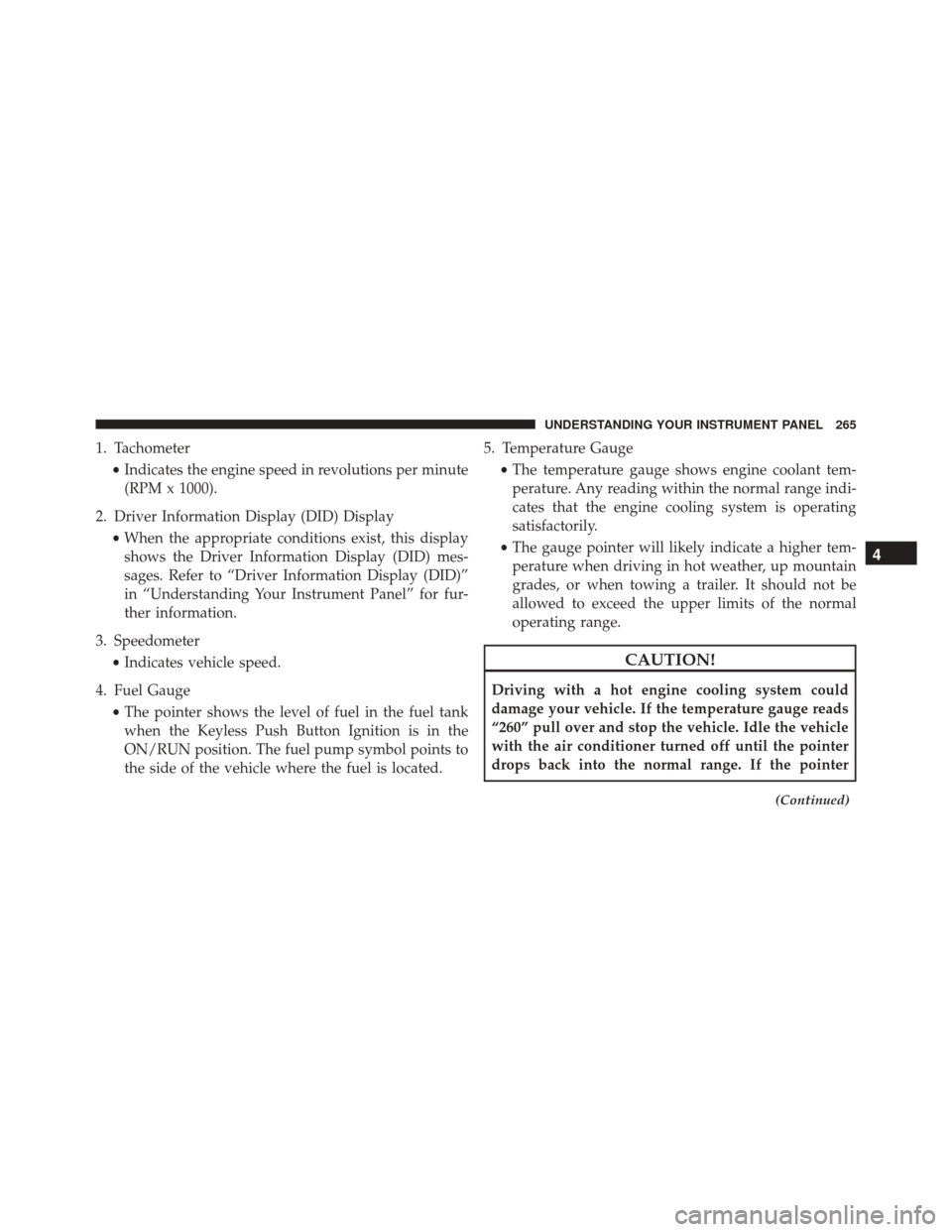
1. Tachometer•Indicates the engine speed in revolutions per minute
(RPM x 1000).
2. Driver Information Display (DID) Display •When the appropriate conditions exist, this display
shows the Driver Information Display (DID) mes-
sages. Refer to “Driver Information Display (DID)”
in “Understanding Your Instrument Panel” for fur-
ther information.
3. Speedometer •Indicates vehicle speed.
4. Fuel Gauge •The pointer shows the level of fuel in the fuel tank
when the Keyless Push Button Ignition is in the
ON/RUN position. The fuel pump symbol points to
the side of the vehicle where the fuel is located. 5. Temperature Gauge
•The temperature gauge shows engine coolant tem-
perature. Any reading within the normal range indi-
cates that the engine cooling system is operating
satisfactorily.
• The gauge pointer will likely indicate a higher tem-
perature when driving in hot weather, up mountain
grades, or when towing a trailer. It should not be
allowed to exceed the upper limits of the normal
operating range.
CAUTION!
Driving with a hot engine cooling system could
damage your vehicle. If the temperature gauge reads
“260” pull over and stop the vehicle. Idle the vehicle
with the air conditioner turned off until the pointer
drops back into the normal range. If the pointer
(Continued)
4
UNDERSTANDING YOUR INSTRUMENT PANEL 265
Page 277 of 661

Electronic Throttle Control (ETC) Warning Light
Red TelltaleLight What It Means
Electronic Throttle Control (ETC) Warning Light
This light informs you of a problem with the Electronic Throttle Control (ETC) system. If a
problem is detected while the engine is running, the light will either stay on or flash de-
pending on the nature of the problem. Cycle the ignition key when the vehicle is safely and
completely stopped and the transmission is placed in the PARK position. The light should
turn off. If the light remains on with the engine running, your vehicle will usually be driv-
able; however, see an authorized dealer for service as soon as possible.
If the light continues to flash when the engine is running, immediate service is required and
you may experience reduced performance, an elevated/rough idle, or engine stall and your
vehicle may require towing. The light will come on when the ignition is first turned to ON/
RUN and remain on briefly as a bulb check. If the light does not come on during starting,
have the system checked by an authorized dealer.
4
UNDERSTANDING YOUR INSTRUMENT PANEL 275
Page 281 of 661

Yellow Telltale Indicator Lights
Engine Check/Malfunction Indicator Light (MIL)
Yellow TelltaleLight What It Means
Engine Check/Malfunction Indicator Light (MIL)
The Engine Check/Malfunction Indicator Light (MIL) is a part of an Onboard Diagnostic
System called OBD II that monitors engine and automatic transmission control systems. The
light will illuminate when the ignition is in the ON position before engine start. If the bulb
does not come on when turning the key from OFF to ON/RUN, have the condition checked
promptly.
Certain conditions, such as a loose or missing gas cap, poor quality fuel, etc., may illuminate
the light after engine start. The vehicle should be serviced if the light stays on through sev-
eral typical driving styles. In most situations, the vehicle will drive normally and will not
require towing.
When the engine is running, the MIL may flash to alert serious conditions that could lead to
immediate loss of power or severe catalytic converter damage. The vehicle should be ser-
viced as soon as possible if this occurs.4
UNDERSTANDING YOUR INSTRUMENT PANEL 279
Page 410 of 661
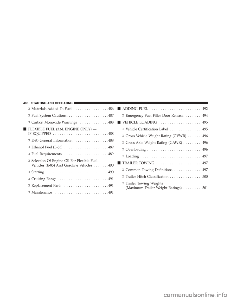
▫Materials Added To Fuel ................486
▫ Fuel System Cautions ...................487
▫ Carbon Monoxide Warnings .............488
� FLEXIBLE FUEL (3.6L ENGINE ONLY) —
IF EQUIPPED ........................ .488
▫ E-85 General Information ...............488
▫ Ethanol Fuel (E-85) ....................489
▫ Fuel Requirements ....................489
▫ Selection Of Engine Oil For Flexible Fuel
Vehicles (E-85) And Gasoline Vehicles .......490
▫ Starting ........................... .490
▫ Cruising Range ...................... .491
▫ Replacement Parts ....................491
▫ Maintenance ....................... .491�
ADDING FUEL ....................... .492
▫ Emergency Fuel Filler Door Release .........494
� VEHICLE LOADING ....................495
▫ Vehicle Certification Label ...............495
▫ Gross Vehicle Weight Rating (GVWR) .......496
▫ Gross Axle Weight Rating (GAWR) .........496
▫ Overloading ........................ .496
▫ Loading ........................... .497
� TRAILER TOWING .....................497
▫ Common Towing Definitions .............497
▫ Trailer Hitch Classification ...............500
▫ Trailer Towing Weights
(Maximum Trailer Weight Ratings) .........501
408 STARTING AND OPERATING