2016 BMW M4 display
[x] Cancel search: displayPage 175 of 228

Wheels and tyresVehicle equipment
This chapter describes all standard, national
and special equipment provided in the model
series. Equipment not available in the vehicle is
therefore also described, for example the se‐
lected special equipment or national version.
This also applies to safety-relevant functions
and systems. Comply with the relevant na‐
tional regulations when using the correspond‐
ing functions and systems.
Tyre pressures Information for your safety
A tyre’s condition and pressure influence the
following:▷Operating life of the tyre.▷Driving safety.▷Driving comfort.
Checking tyre pressures
WARNING
A tyre with inadequate or missing tyre in‐
flation pressure impairs driving properties, for example steering and braking. Danger of acci‐
dents. Check tyre inflation pressure regularly
and adjust as necessary, for example twice a
month or before any long journey.◀
Tyres have a natural, uniform tyre pressure
loss.
Tyres heat up when driving and with the tem‐
perature of the tyre, the tyre filling pressure in‐
creases. The tyre filling pressure data relate to
cold tyres or tyres at ambient temperature.
Only check the tyre pressure when the tyres
are cold. In other words, after driving for a max‐
imum of 2 km or if the vehicle has been parked
for at least 2 hours.
Inflating devices can display a pressure as
much as 0.1 bar too low.
With runflat indicator: reinitialise the runflat in‐
dicator after adjusting tyre pressures.
With tyre pressure monitor: reset the tyre pres‐
sure monitor after adjusting the tyre pressure
to a new value.
Tyre inflation pressures
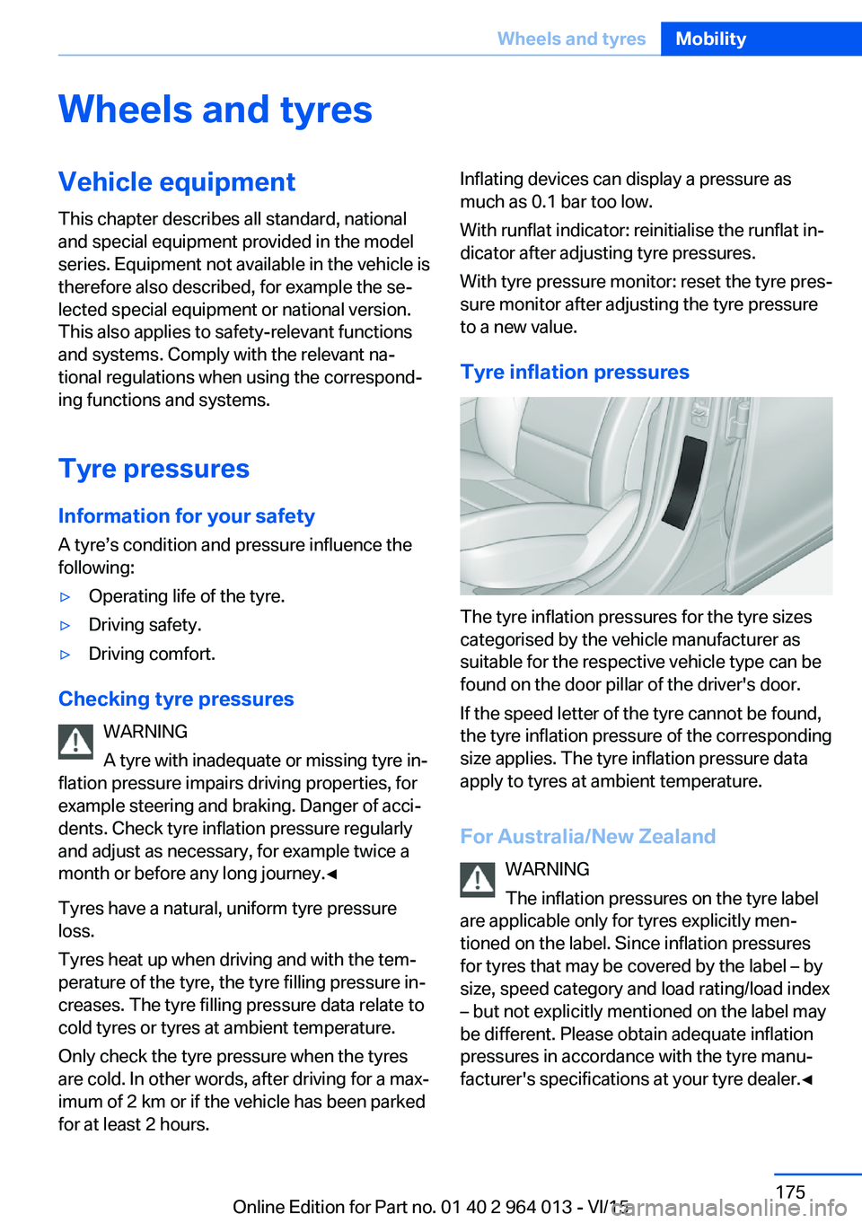
The tyre inflation pressures for the tyre sizes
categorised by the vehicle manufacturer as
suitable for the respective vehicle type can be
found on the door pillar of the driver's door.
If the speed letter of the tyre cannot be found,
the tyre inflation pressure of the corresponding
size applies. The tyre inflation pressure data
apply to tyres at ambient temperature.
For Australia/New Zealand WARNING
The inflation pressures on the tyre label
are applicable only for tyres explicitly men‐
tioned on the label. Since inflation pressures
for tyres that may be covered by the label – by
size, speed category and load rating/load index
– but not explicitly mentioned on the label may
be different. Please obtain adequate inflation
pressures in accordance with the tyre manu‐
facturer's specifications at your tyre dealer.◀
Seite 175Wheels and tyresMobility175
Online Edition for Part no. 01 40 2 964 013 - VI/15
Page 179 of 228

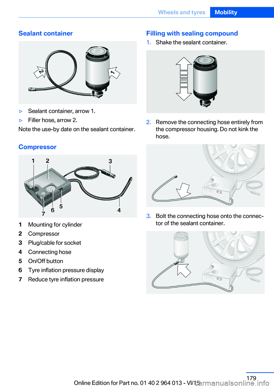
Sealant container▷Sealant container, arrow 1.▷Filler hose, arrow 2.
Note the use-by date on the sealant container.
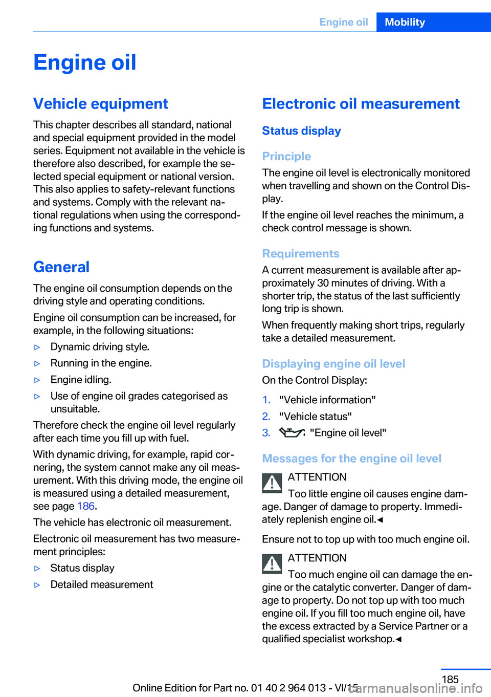
Compressor
1Mounting for cylinder2Compressor3Plug/cable for socket4Connecting hose5On/Off button6Tyre inflation pressure display7Reduce tyre inflation pressureFilling with sealing compound1.Shake the sealant container.2.Remove the connecting hose entirely from
the compressor housing. Do not kink the
hose.3.Bolt the connecting hose onto the connec‐
tor of the sealant container.Seite 179Wheels and tyresMobility179
Online Edition for Part no. 01 40 2 964 013 - VI/15
Page 185 of 228

Engine oilVehicle equipment
This chapter describes all standard, national
and special equipment provided in the model
series. Equipment not available in the vehicle is
therefore also described, for example the se‐
lected special equipment or national version.
This also applies to safety-relevant functions
and systems. Comply with the relevant na‐
tional regulations when using the correspond‐
ing functions and systems.
General
The engine oil consumption depends on the
driving style and operating conditions.
Engine oil consumption can be increased, for
example, in the following situations:▷Dynamic driving style.▷Running in the engine.▷Engine idling.▷Use of engine oil grades categorised as
unsuitable.
Therefore check the engine oil level regularly
after each time you fill up with fuel.
With dynamic driving, for example, rapid cor‐
nering, the system cannot make any oil meas‐
urement. With this driving mode, the engine oil
is measured using a detailed measurement,
see page 186.
The vehicle has electronic oil measurement.
Electronic oil measurement has two measure‐
ment principles:
▷Status display▷Detailed measurementElectronic oil measurement
Status display
Principle
The engine oil level is electronically monitored
when travelling and shown on the Control Dis‐
play.
If the engine oil level reaches the minimum, a
check control message is shown.
RequirementsA current measurement is available after ap‐
proximately 30 minutes of driving. With a
shorter trip, the status of the last sufficiently
long trip is shown.
When frequently making short trips, regularly
take a detailed measurement.
Displaying engine oil level On the Control Display:1."Vehicle information"2."Vehicle status"3. "Engine oil level"
Messages for the engine oil level
ATTENTION
Too little engine oil causes engine dam‐
age. Danger of damage to property. Immedi‐
ately replenish engine oil.◀
Ensure not to top up with too much engine oil. ATTENTION
Too much engine oil can damage the en‐
gine or the catalytic converter. Danger of dam‐
age to property. Do not top up with too much
engine oil. If you fill too much engine oil, have
the excess extracted by a Service Partner or a
qualified specialist workshop.◀
Seite 185Engine oilMobility185
Online Edition for Part no. 01 40 2 964 013 - VI/15
Page 186 of 228

Different messages are shown on the display,
depending on the engine oil level. Follow these
messages.
If there is too little engine oil, within the next
200 km, approximately 120 miles top up en‐
gine oil, see page 186.
Detailed measurement
Principle In the detailed measurement, the engine oil
level is checked and shown on a scale.
If the engine oil level reaches the minimum, a
Check Control message is shown.
During the measurement, the idle speed is
slightly raised.
Requirements▷Vehicle is on an even road.▷Manual gearbox: gear lever in neutral posi‐
tion, clutch and accelerator pedal not de‐
pressed.▷M double clutch transmission: selector
lever in selector lever position N and accel‐
erator pedal not depressed.▷Engine is running and is at operating tem‐
perature.
Carrying out a detailed measurement
Carry out a detailed measurement of the en‐
gine oil level:
1."Vehicle information"2."Vehicle status"3. "Measure engine oil level"4."Start measurement"
The engine oil level is checked and shown on a
scale.
Duration: approximately 1 minute.
Adding engine oil
Notes ATTENTION
Too little engine oil causes engine dam‐
age. Danger of damage to property.
Top up the engine oil within the next 200 km,
approximately 120 miles.◀
ATTENTION
Too much engine oil can damage the en‐
gine or the catalytic converter. Danger of dam‐
age to property. Do not top up with too much
engine oil. If you fill too much engine oil, have
the excess extracted by a Service Partner or a
qualified specialist workshop.◀
WARNING
Service products, for example oils,
greases, coolants and fuels, can contain sub‐
stances that are harmful to health. Danger of
injury or life. Comply with the notes on the
containers. Do not allow service products to
come into contact with clothing, skin eyes. Do
not pour service products into other bottles.
Keep service products out of the reach of chil‐
dren.◀
General Do not top up engine oil unless message isdisplayed in instrument cluster. The top-up
amount is specified in the message on the in‐
strument cluster.
Switch off the ignition and securely stop the
vehicle before topping up with engine oil.
Spilled engine oil can damage carbon parts.
Wipe up spilled engine oil with a lint-free cloth.
Overview
The oil filler neck is in the engine compart‐
ment, see page 182.Seite 186MobilityEngine oil186
Online Edition for Part no. 01 40 2 964 013 - VI/15
Page 191 of 228

MaintenanceVehicle equipment
This chapter describes all standard, national
and special equipment provided in the model
series. Equipment not available in the vehicle is
therefore also described, for example the se‐
lected special equipment or national version.
This also applies to safety-relevant functions
and systems. Comply with the relevant na‐
tional regulations when using the correspond‐
ing functions and systems.
BMW Maintenance System
The maintenance system points out the nec‐
essary maintenance measures and so sup‐
ports in maintaining the road and operational
safety of the vehicle.
Scopes and intervals may vary depending on
national version. Replacement work, spare
parts, operating materials and wear material
are calculated separately. Further information
is available from a Service Partner or a qualified
specialist workshop.
Condition Based Service,
CBS
Sensors and advanced algorithms monitor the
conditions in which your vehicle is used. Con‐
dition Based Service uses this information to
calculate the maintenance requirements.
The system thus enables adaptation of the
scope of maintenance to the individual usage
profile.
Detailed information on service requirements,
see page 87, can be displayed at the Control
Display.Service data in the remote control
Information on maintenance requirements is
continually saved in the remote control. The Service Partner or a qualified specialist work‐
shop can read out this data and suggest an op‐
timised maintenance scope for your vehicle.
This is why you should hand over the remote
control that was last used for driving to your
service advisor with the vehicle.
Periods out of use
Immobilisation periods with the vehicle battery
disconnected are not taken into account.
Updating the time-dependent maintenance
scope such as brake fluid and any engine oil
and microfilter or activated carbon filter can be
done by a Service Partner or a qualified spe‐
cialist workshop.
Service history Have maintenance and repair carried out by a
Service Partner or a qualified specialist work‐
shop.
The maintenance work carried out is entered in
the proof of maintenance and the vehicle data.
The entries are, just like a service booklet, evi‐
dence of regular maintenance.
If an entry is made in the electronic service his‐
tory of the vehicle, service-relevant data is not
only saved in the vehicle but also on the central
IT systems of BMW AG, Munich.
The data entered in the electronic service his‐
tory can also be viewed by the new vehicle
owner after a change of vehicle owner. In addi‐
tion, all Service Partners and other authorised
and qualified specialist workshops can view
the data entered in the electronic service his‐
tory.Seite 191MaintenanceMobility191
Online Edition for Part no. 01 40 2 964 013 - VI/15
Page 192 of 228

The vehicle owner can contact his/her Service
Partner or a qualified specialist workshop to
object to the entry in the electronic service his‐
tory, the associated data storage in the vehicle
and data transfer to the vehicle manufacturer,
in relation to his/her time as the vehicle owner.
In that case, no entry is made in the electronic
service history of the vehicle.
Maintenance entered is shown on the Control
Display, see page 88.
For Australia/New Zealand:
maintenance
No maintenance work other than normal main‐
tenance is required to keep the emission levels
of your vehicle within the design limits.
Socket for on-board
diagnosis, OBD
Note ATTENTION
Incorrect use of the on-board diagnosis
socket can result in malfunctions in the vehi‐
cle. Danger of damage to property. The on-
board diagnosis socket is only allowed to be
used by a Service Partner, a qualified specialist
workshop or other authorised persons.◀Position
The OBD socket for checking components de‐
finitive in terms of the composition of the ex‐
haust emissions is on the driver's side.
Emissions
▷The warning light flashes:
Engine malfunction that could
damage the catalytic converter.
Have the vehicle checked as soon
as possible.▷The warning light is illuminated:
Deterioration of exhaust emissions. Have
the vehicle checked as soon as possible.
Recycling
The manufacturer of your vehicle recommends
handing the vehicle in at a take-back point
nominated by the manufacturer at the end of
its life cycle. The regulations concerning the
returning of end-of-life vehicles may vary from
country to country. Further information is avail‐
able from a Service Partner or a qualified spe‐
cialist workshop.
Seite 192MobilityMaintenance192
Online Edition for Part no. 01 40 2 964 013 - VI/15
Page 199 of 228

5.Install the cable on the handle of the emer‐
gency release and engage the handle into
the fastening.6.Fit the bracket for the warning triangle.7.Attach the warning triangle.
Tail lights, number plate lights and
centre brake light
These lights use LED technology. Contact a
Service Partner or a qualified specialist work‐
shop in the case of a defect.
Changing a wheel
Notes
When using sealants, immediate wheel change
in the event of loss of tyre pressure in case of
puncture is not required.
As a result, no spare wheel is available.
The tools for changing wheels are available as
optional accessories from a Service Partner or
a qualified specialist workshop.
Jack mounting points
The jack mounting points are located in the il‐
lustrated positions.
Thiefproof wheel studs
The adapter of the thiefproof wheel studs can
be found in the tool kit or in an oddments tray
in the tool kit.
▷Wheel stud, arrow 1.▷Adapter, arrow 2.
Removing
1.Place the adapter on the wheel stud.2.Unscrew wheel stud.
After reattaching the wheel stud, remove the
adapter again.
Car battery Maintenance
The battery is maintenance-free.
More information regarding the battery can be
enquired with a Service Partner or a qualified
specialist workshop.
Replacing the battery ATTENTION
Vehicle batteries that have been categor‐
ised by the manufacturer of the vehicle as un‐
suitable can damage systems, or prevent func‐
tions from being carried out. Danger of
damage to property. Only use vehicle batteries
that have been classified as suitable by the ve‐
hicle manufacturer.◀
When the vehicle battery has been changed,
have the battery registered on the vehicle by a
Service Partner or a qualified specialist work‐
shop to ensure that all comfort functions are
fully available and any appropriate Check Con‐
trol messages are no longer displayed.
Seite 199Replacing partsMobility199
Online Edition for Part no. 01 40 2 964 013 - VI/15
Page 202 of 228

Help in the event of a breakdownVehicle equipment
This chapter describes all standard, national
and special equipment provided in the model
series. Equipment not available in the vehicle is
therefore also described, for example the se‐
lected special equipment or national version.
This also applies to safety-relevant functions
and systems. Comply with the relevant na‐
tional regulations when using the correspond‐
ing functions and systems.
Hazard warning lights
The button is located in the centre console.
Intelligent emergency call
Principle This system can be used for sending an emer‐
gency call in emergency situations.
General Press the SOS button in an emergency only.
Even if no emergency call through BMW is
possible, in some cases an emergency call may still be set up to a public emergency call
number. This depends on factors such as the
specific mobile telephone network and the na‐
tional regulations.
For technical reasons, it might not be possible
to make an emergency call in highly adverse
conditions.
Overview
SOS button in headlining
Requirements
▷SIM card integrated into the vehicle is acti‐
vated.▷Radio ready state is switched on.▷Emergency call system is functional.
Making an emergency call
1.Briefly press the cover flap to open it.2.Press the SOS button until the LED on the
button is illuminated green.▷LED illuminated green: emergency call ac‐
tivated.
If a cancellation request is shown on the
display, the emergency call can be cancel‐
led.
If the situation permits, wait in the vehicle
until voice contact has been established.▷LED flashes green when the connection to
the emergency number has been estab‐
lished.
When an emergency call is sent via BMW,
data is sent to the emergency call centre in
order to decide what rescue measures areSeite 202MobilityHelp in the event of a breakdown202
Online Edition for Part no. 01 40 2 964 013 - VI/15