Page 73 of 96

PERIODIC MAINTENANCE AND ADJUSTMENT
6-28
6
EAU23285
Checking the steerin gWorn or loose steering bearings may
cause danger. Therefore, the operation
of the steering must be checked as fol-
lows at the intervals specified in the
periodic maintenance and lubrication
chart.
1. Raise the front wheel off the ground. (See page 6-36.)
WARNING! To avoi d injury, se-
curely support the vehicle so
there is no dan ger of it fallin g
over.
[EWA10752]
2. Hold the lower ends of the front fork legs and try to move them for-
ward and backward. If any free
play can be felt, have a Yamaha
dealer check or repair the steer-
ing.
EAU23292
Checkin g the wheel bearin gsThe front and rear wheel bearings must
be checked at the intervals specified in
the periodic maintenance and lubrica-
tion chart. If there is play in the wheel
hub or if the wheel does not turn
smoothly, have a Yamaha dealer
check the wheel bearings.
EAU62521
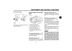
BatteryThe battery is located under the rider
seat. (See page 3-18.)
This model is equipped with a VRLA
(Valve Regulated Lead Acid) battery.
There is no need to check the electro-
lyte or to add distilled water. However,
the battery lead connections need to
be checked and, if necessary, tight-
ened.
WARNING
EWA10761
Electrolyte is poisonous an d
d an gerous since it contains sul-
furic aci d, which causes severe1. Battery
2. Negative battery lead (black)
3. Positive battery lead (red)
1
2
3
UB02E0E0.book Page 28 Thursday, January 15, 2015 3:39 PM
Page 74 of 96

PERIODIC MAINTENANCE AND ADJUSTMENT
6-29
6b
urns. Avoi d any contact with
skin, eyes or clothin g an d al-
ways shiel d your eyes when
workin g near b atteries. In case
of contact, ad minister the fol-
lowin g FIRST AID.
EXTERNAL: Flush with plenty of water.
INTERNAL: Drink lar ge quan-
tities of water or milk an d im-
me diately call a physician.
EYES: Flush with water for 15 minutes an d seek prompt
me dical attention.
Batteries pro duce explosive hy-
d ro gen gas. Therefore, keep
sparks, flames, ci garettes, etc.,
away from the battery an d pro-
vi de sufficient ventilation when
char gin g it in an enclose d
space.
KEEP THIS AND ALL BATTER-
IES OUT OF THE REACH OF
CHILDREN.
NOTICE
ECA10621
Never attempt to remove the b attery
cell seals, as this woul d permanently
d amag e the battery.To char ge the battery
Have a Yamaha dealer charge the bat-
tery as soon as possible if it seems to
have discharged. Keep in mind that the
battery tends to discharge more quick-
ly if the vehicle is equipped with op-
tional electrical accessories.NOTICE
ECA16522
To char ge a VRLA (Valve Re gulate d
Lea d Aci d) battery, a special (con-
stant-volta ge) battery char ger is re-
quire d. Usin g a conventional battery
char ger will damag e the b attery.To store the battery
1. If the vehicle will not be used for more than one month, remove the
battery, fully charge it, and then
place it in a cool, dry place.
NOTICE: When removin g the
b attery, be sure the key is turne
d to “ ”, then disconnect
the ne gative lead b efore discon-
nectin g the positive lea d.
[ECA17712]
2. If the battery will be stored for
more than two months, check it at
least once a month and fully
charge it if necessary.
3. Fully charge the battery before in- stallation. NOTICE: When install-
in g the b attery, be sure the key
is turne d to “ ”, then connect
the positive lea d before con-
nectin g the ne gative lea d.
[ECA17722]
4. After installation, make sure that
the battery leads are properly con-
nected to the battery terminals.NOTICE
ECA16531
Always keep the b attery charged .
Storin g a d ischar ged battery can
cause permanent battery damag e.
UB02E0E0.book Page 29 Thursday, January 15, 2015 3:39 PM
Page 75 of 96

To access the main fuse, proceed as
follows.
1. Remove the pa")
PERIODIC MAINTENANCE AND ADJUSTMENT
6-30
6
EAUN0820
Replacing the fusesThe main fuse is located under the
passenger seat. (See page 3-18.)
To access the main fuse, proceed as
follows.
1. Remove the passenger seat. (See page 3-18.)
2. Remove the tray by removing the quick fasteners.
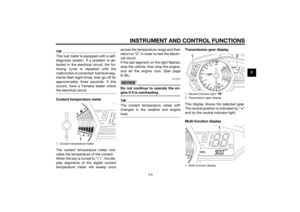
3. Pull back the starter relay cover, and then disconnect the starter re-
lay coupler as shown. 4. Connect the starter relay coupler,
and then slide the cover to its orig-
inal position.
5. Place the tray in its original posi- tion, and then install the quick fas-
teners.
6. Install the passenger seat.
Fuse box 1 is located behind the center
cover. (See page 3-18.) Fuse
box 11. Quick fastener
2. Tray
2
1
1. Starter relay cover
2. Starter relay coupler
3. Main fuse
4. Spare main fuse
1
2
34
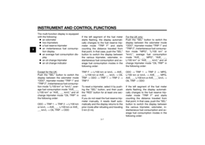
1. Fuse box 1
1. Ignition fuse
2. Signaling system fuse
3. ABS control unit fuse
4. Backup fuse (for clock)
5. Headlight fuse
6. Radiator fan motor fuse
7. Spare fuse17
123
56
4
UB02E0E0.book Page 30 Thursday, January 15, 2015 3:39 PM
Page 76 of 96

Fuse
box 2
If a fuse is blown, replace it as follows. 1. Turn the key to “ ” and turn off
th")
PERIODIC MAINTENANCE AND ADJUSTMENT
6-31
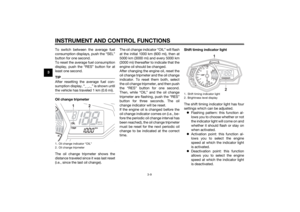
6Fuse box 2 is located under the rider
seat. (See page 3-18.)
Fuse
box 2
If a fuse is blown, replace it as follows. 1. Turn the key to “ ” and turn off
the electrical circuit in question.
2. Remove the blown fuse, and then install a new fuse of the specified
amperage. WARNING! Do not
use a fuse of a hi gher ampera ge
ratin g than recommen ded to
avoi d causin g extensive d am-
a g e to the electrical system an d
possi bly a fire.
[EWA15132]
3. Turn the key to “ ” and turn on
the electrical circuit in question to
check if the device operates.
4. If the fuse immediately blows again, have a Yamaha dealer
check the electrical system.
1. Fuse box 2
1. Spare fuse
2. ABS solenoid fuse
3. ABS motor fuse
1
123
Specifie d fuses:
Main fuse: 30.0 A
Headlight fuse:
15.0 A
Signaling system fuse: 7.5 A
Ignition fuse: 15.0 A
Radiator fan motor fuse:
7.5 A
ABS motor fuse: 30.0 A
ABS solenoid fuse: 15.0 A
ABS control unit fuse:
7.5 A
Backup fuse: 7.5 A
UB02E0E0.book Page 31 Thursday, January 15, 2015 3:39 PM
Page 77 of 96

PERIODIC MAINTENANCE AND ADJUSTMENT
6-32
6
EAU39014
Replacing a hea dlig ht bul bThis model is equipped with halogen
bulb headlights. If a headlight bulb
burns out, replace it as follows.NOTICE
ECA10651
Take care not to damag e the follow-
in g parts:
Hea dlig ht bul b
Do not touch the glass part of
the hea dlig ht bul b to keep it free
from oil, otherwise the transpar-
ency of the g lass, the luminosity
of the b ulb, an d the b ulb life will
b e ad versely affected . Thor-
ou ghly clean off any d irt and fin-
g erprints on the head light bul b
using a cloth moistene d with al-
cohol or thinner.
Hea dlig ht lens
Do not affix any type of tinted
film or stickers to the head light
lens.
Do not use a hea dlig ht bul b of a
watta ge hi gher than specified .
1. Remove the headlight bulb cover
by turning it counterclockwise.
2. Disconnect the headlight coupler. 3. Unhook the headlight bulb holder,
and then remove the burnt-out
bulb.
4. Place a new headlight bulb into position, and then secure it with
the bulb holder.
5. Connect the headlight coupler.1. Do not touch the glass part of the bulb.
1. Headlight bulb cover1
1. Headlight coupler
1. Headlight bulb holder
1
1
UB02E0E0.book Page 32 Thursday, January 15, 2015 3:39 PM
Page 78 of 96
PERIODIC MAINTENANCE AND ADJUSTMENT
6-33
66. Install the headlight bulb cover by
turning it clockwise.
7. Have a Yamaha dealer adjust the headlight beam if necessary.
EAU39021
Auxiliary li ght bul bIf the auxiliary light does not come on,
have a Yamaha dealer check the elec-
trical circuit or replace the bulb.
EAU24182
Tail/ brake li ghtThis model is equipped with an LED-
type tail/brake light.
If the tail/brake light does not come on,
have a Yamaha dealer check it.
1. Auxiliary light1
UB02E0E0.book Page 33 Thursday, January 15, 2015 3:39 PM
Page 79 of 96
PERIODIC MAINTENANCE AND ADJUSTMENT
6-34
6
EAU62590
Replacing a turn sig nal light
b ul b1. Remove the turn signal light lens
by removing the screw.
2. Remove the turn signal light bulb socket (together with the bulb) by
turning it counterclockwise. 3. Remove the burnt-out bulb by
pulling it out.
4. Insert a new bulb into the socket.
5. Install the socket (together with the bulb) by turning it clockwise.
6. Install the turn signal light lens by installing the screw. NOTICE: Do
not overti ghten the screw, oth-
erwise the lens may break.
[ECA11192] EAU62670
Replacin
g the license plate
lig ht bul b1. Remove the mudguard by remov-
ing the quick fasteners.
2. Remove the rear fender lower panel by removing the bolts and
screws.
1. Turn signal light lens
2. Screw
1
2
1. Turn signal light bulb socket
1
1. Mudguard
2. Quick fastener
12
UB02E0E0.book Page 34 Thursday, January 15, 2015 3:39 PM
Page 80 of 96
 by pulling it out.
4. Remove the burnt-out bulb by pulling it out. 5. Insert a new bulb")
PERIODIC MAINTENANCE AND ADJUSTMENT
6-35
63. Remove the license plate light
bulb socket (together with the
bulb) by pulling it out.
4. Remove the burnt-out bulb by pulling it out. 5. Insert a new bulb into the socket.
6. Install the socket (together with
the bulb) by pushing it in.
7. Install the rear fender lower panel by installing the bolts and screws.
8. Install the mudguard by installing the quick fasteners.
EAU24351
Supportin g the motorcycleSince this model is not equipped with a
centerstand, follow these precautions
when removing the front and rear
wheel or performing other mainte-
nance requiring the motorcycle to
stand upright. Check that the motorcy-
cle is in a stable and level position be-
fore starting any maintenance. A
strong wooden box can be placed un-
der the engine for added stability.
To service the front wheel
1. Stabilize the rear of the motorcy- cle by using a motorcycle stand
or, if an additional motorcycle
stand is not available, by placing a
jack under the frame in front of the
rear wheel.
2. Raise the front wheel off the ground by using a motorcycle
stand.
To service the rear wheel
Raise the rear wheel off the ground by
using a motorcycle stand or, if a motor-
cycle stand is not available, by placing
1. Bolt
2. Screw
3. Rear fender lower panel
1. License plate light bulb
2. License plate light bulb socket
3
2
1 2
2
121
UB02E0E0.book Page 35 Thursday, January 15, 2015 3:39 PM