Page 25 of 96

INSTRUMENT AND CONTROL FUNCTIONS
3-10
3
Brightness: this function allows
you to adjust the brightness of the
indicator light.
To adjust the shift timing indicator light
1. Turn the key to “ ”.
2. Push and hold the “SEL” button.
3. Turn the key to “ ”, and then re- lease the “SEL” button after five
seconds. The shift timing indicator
light can now be adjusted.
To set the flashing pattern1. Push the “RES” button to select one of the following flashing pat-
tern settings: On: the indicator light stays
on when activated. (This set-
ting is selected when the indi-
cator light stays on.)
Flash: the indicator light
flashes when activated. (This
setting is selected when the
indicator light flashes four
times per second.)
Off: the indicator light is deac-
tivated; in other words, it
does not come on or flash. (This setting is selected when
the indicator light flashes
once every two seconds.)
2. Push the “SEL” button to confirm the selected flashing pattern. The
shift timing indicator light changes
to the activation point setting
mode.
The tachometer will show the current
setting r/min for the activation point
and deactivation point setting modes.
To set the shift activation point
TIPThe shift timing indicator light activa-
tion point can be set between 7000
r/min and 13500 r/min. From 7000
r/min to 12000 r/min, the indicator light
can be set in increments of 500 r/min.
From 12000 r/min to 13500 r/min, the
indicator light can be set in increments
of 200 r/min.1. Push the “RES” button to select the desired engine speed for acti-
vating the indicator light. 2. Push the “SEL” button to confirm
the selected engine speed. The
control mode changes to the de-
activation point setting mode.
To set the deactivation point
TIP The shift timing indicator light de-
activation point can be set be-
tween 7000 r/min and 13500
r/min. From 7000 r/min to 12000
r/min, the indicator light can be set
in increments of 500 r/min. From
12000 r/min to 13500 r/min, the in-
dicator light can be set in incre-
ments of 200 r/min.
Be sure to set the deactivation
point to a higher engine speed
than for the activation point, other-
wise the shift timing indicator light
will not come on.1. Push the “RES” button to select
the desired engine speed for de-
activating the indicator light.
2. Push the “SEL” button to confirm the selected engine speed. The
control mode changes to the
brightness setting mode.
UB02E0E0.book Page 10 Thursday, January 15, 2015 3:39 PM
Page 26 of 96

INSTRUMENT AND CONTROL FUNCTIONS
3-11
3To adjust the brightness
1. Push the “RES” button to select
the desired shift indicator light
brightness level.
2. Push the “SEL” button to confirm the selected brightness level. The
display exits the shift timing light
control mode and returns to the
standard multi-function display
mode.
Self-d iagnosis device
This model is equipped with a self-di-
agnosis device for various electrical
circuits. If a problem is detected in any of those
circuits, the engine trouble warning
light will come on and the display will
indicate an error code.
NOTICE
ECA11591
If the
display in dicates an error
co de, the vehicle shoul d b e checked
as soon as possi ble in or der to avoi d
en gine damag e.
EAU1234H
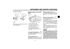
Handle bar switchesLeft
Ri ght
1. Engine trouble warning light “ ”
2. Error code display
2
1
km/hMPH
1. Pass switch “PASS”
2. Dimmer switch “ / ”
3. Turn signal switch “ / ”
4. Horn switch “ ”
1. Engine stop switch “ / ”
2. Start switch “ ”
4312
21
UB02E0E0.book Page 11 Thursday, January 15, 2015 3:39 PM
Page 27 of 96

INSTRUMENT AND CONTROL FUNCTIONS
3-12
3
EAU12361
Pass switch “PASS”
Press this switch to flash the headlight.
EAU62540
Dimmer switch “ / ”
Set this switch to “ ” for the high
beam and to “ ” for the low beam.TIPWhen the switch is set to low beam,
only the right headlight bulb comes on.
When the switch is set to high beam,
both headlight bulbs come on.
EAU12461
Turn signal switch “ / ”
To signal a right-hand turn, push this
switch to “ ”. To signal a left-hand
turn, push this switch to “ ”. When
released, the switch returns to the cen-
ter position. To cancel the turn signal
lights, push the switch in after it has re-
turned to the center position.
EAU12501
Horn switch “ ”
Press this switch to sound the horn.
EAU12661
En gine stop switch “ / ”
Set this switch to “ ” before starting
the engine. Set this switch to “ ” to
stop the engine in case of an emergen-
cy, such as when the vehicle overturns
or when the throttle cable is stuck.
EAU12713
Start switch “ ”
Push this switch to crank the engine
with the starter. See page 5-1 for start-
ing instructions prior to starting the en-
gine.
EAU62500
The engine trouble warning light will
come on when the key is turned to “ ”
and the start switch is pushed, but this
does not indicate a malfunction.
EAU12821
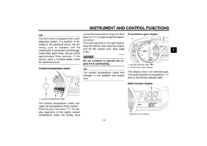
Clutch leverThe clutch lever is located at the left
handlebar grip. To disengage the
clutch, pull the lever toward the han-
dlebar grip. To engage the clutch, re-
lease the lever. The lever should be
pulled rapidly and released slowly for
smooth clutch operation.
The clutch lever is equipped with a
clutch switch, which is part of the igni-
tion circuit cut-off system. (See page
3-22.)1. Clutch lever
1
UB02E0E0.book Page 12 Thursday, January 15, 2015 3:39 PM
Page 28 of 96
INSTRUMENT AND CONTROL FUNCTIONS
3-13
3
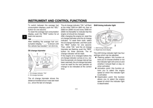
EAU12872
Shift pedalThe shift pedal is located on the left
side of the motorcycle and is used in
combination with the clutch lever when
shifting the gears of the 6-speed con-
stant-mesh transmission equipped on
this motorcycle.
EAU12892
Brake leverThe brake lever is located on the right
side of the handlebar. To apply the
front brake, pull the lever toward the
throttle grip.
EAU12944
Brake ped alThe brake pedal is located on the right
side of the motorcycle. To apply the
rear brake, press down on the brake
pedal.
1. Shift pedal
1
1. Brake lever
1
1. Brake pedal
1
UB02E0E0.book Page 13 Thursday, January 15, 2015 3:39 PM
Page 29 of 96
 features a dual electronic con-
trol system, which acts on the front and
rear brakes independently.
Operate")
INSTRUMENT AND CONTROL FUNCTIONS
3-14
3
EAU63040
ABSThe Yamaha ABS (Anti-lock Brake
System) features a dual electronic con-
trol system, which acts on the front and
rear brakes independently.
Operate the brakes with ABS as you
would conventional brakes. If the ABS
is activated, a pulsating sensation may
be felt at the brake lever or brake ped-
al. In this situation, continue to apply
the brakes and let the ABS work; do
not “pump” the brakes as this will re-
duce braking effectiveness.
WARNING
EWA16051
Always keep a sufficient distance
from the vehicle ahea d to match the
ri din g speed even with ABS.
The ABS performs best with
lon g b rakin g d istances.
On certain surfaces, such as
rou gh or g ravel roa ds, the b rak-
in g d istance may be lon ger with
the ABS than without.The ABS is monitored by an ECU,
which will revert the system to conven-
tional braking if a malfunction occurs.
TIP The ABS performs a self-diagno-
sis test each time the vehicle first
starts off after the key is turned to
“ON” and the vehicle has traveled
at a speed of 10 km/h (6 mi/h) or
higher. During this test, a “click-
ing” noise can be heard from the
hydraulic control unit, and if the
brake lever or brake pedal is even
slightly applied, a vibration can be
felt at the lever and pedal, but
these do not indicate a malfunc-
tion.
This ABS has a test mode which
allows the owner to experience
the pulsation at the brake lever or
brake pedal when the ABS is op-
erating. However, special tools are
required, so please consult your
Yamaha dealer.NOTICE
ECA20100
Be careful not to d amage the wheel
sensor or wheel sensor rotor; other-
wise, improper performance of the
ABS will result.
1. Front wheel sensor
2. Front wheel sensor rotor
1. Rear wheel sensor
2. Rear wheel sensor rotor
1 2
1
2
UB02E0E0.book Page 14 Thursday, January 15, 2015 3:39 PM
Page 30 of 96

INSTRUMENT AND CONTROL FUNCTIONS
3-15
3
EAU13075
Fuel tank capTo open the fuel tank cap
Open the fuel tank cap lock cover, in-
sert the key into the lock, and then turn
it 1/4 turn clockwise. The lock will be
released and the fuel tank cap can be
opened.
To close the fuel tank cap1. Push the fuel tank cap into posi- tion with the key inserted in the
lock.
2. Turn the key counterclockwise to the original position, remove it,
and then close the lock cover.
TIPThe fuel tank cap cannot be closed un-
less the key is in the lock. In addition,
the key cannot be removed if the cap is
not properly closed and locked.
WARNING
EWA11092
Make sure that the fuel tank cap is
properly close d after fillin g fuel.
Leakin g fuel is a fire hazar d.
EAU13222
FuelMake sure there is sufficient gasoline in
the tank.
WARNING
EWA10882
Gasoline an d g asoline vapors are
extremely flamma ble. To avoi d fires
an d explosions an d to re duce the
risk of injury when refuelin g, follow
these instructions.1. Before refueling, turn off the en- gine and be sure that no one is sit-
ting on the vehicle. Never refuel
while smoking, or while in the vi-
cinity of sparks, open flames, or
other sources of ignition such as
the pilot lights of water heaters
and clothes dryers.
2. Do not overfill the fuel tank. When refueling, be sure to insert the
pump nozzle into the fuel tank filler
hole. Stop filling when the fuel
reaches the bottom of the filler
tube. Because fuel expands when
it heats up, heat from the engine or
the sun can cause fuel to spill out
of the fuel tank.
1. Fuel tank cap lock cover
2. Unlock.
2 1
UB02E0E0.book Page 15 Thursday, January 15, 2015 3:39 PM
Page 31 of 96

INSTRUMENT AND CONTROL FUNCTIONS
3-16
3
3. Wipe up any spilled fuel immedi- ately. NOTICE: Immediately
wipe off spille d fuel with a clean,
d ry, soft cloth, since fuel may
d eteriorate painte d surfaces or
plastic parts.
[ECA10072]
4. Be sure to securely close the fuel tank cap.
WARNING
EWA15152
Gasoline is poisonous an d can
cause injury or d eath. Handle gaso-
line with care. Never siphon gasoline
b y mouth. If you shoul d swallow
some gasoline or inhale a lot of gas-
oline vapor, or get some g asoline in
your eyes, see your doctor imme di- ately. If g
asoline spills on your skin,
wash with soap an d water. If gaso-
line spills on your clothin g, chan ge
your clothes.
EAU49743
NOTICE
ECA11401
Use only unlea ded g asoline. The use
of lead ed g asoline will cause severe
d amag e to internal en gine parts,
such as the valves an d piston rin gs,
as well as to the exhaust system.Your Yamaha engine has been de-
signed to use regular unleaded gaso-
line with a research octane number of
95 or higher. If knocking (or pinging)
occurs, use a gasoline of a different brand or premium unleaded fuel. Use
of unleaded fuel will extend spark plug
life and reduce maintenance costs.
Gasohol
There are two types of gasohol: gaso-
hol containing ethanol and that con-
taining methanol. Gasohol containing
ethanol can be used if the ethanol con-
tent does not exceed 10% (E10). Gas-
ohol containing methanol is not
recommended by Yamaha because it
can cause damage to the fuel system
or vehicle performance problems.
1. Fuel tank filler tube
2. Maximum fuel level
2
1
Recommen
ded fuel:
Regular unleaded gasoline (Gasohol
(E10) acceptable)
Fuel tank capacity:
14 L (3.7 US gal, 3.08 Imp.gal)
Fuel reserve amount: 3.0 L (0.79 US gal, 0.66 Imp.gal)
UB02E0E0.book Page 16 Thursday, January 15, 2015 3:39 PM
Page 32 of 96

INSTRUMENT AND CONTROL FUNCTIONS
3-17
3
EAUN0790
Fuel tank breather hose an d
overflow hoseBefore operating the motorcycle:
Check each hose connection.
Check each hose for cracks or
damage, and replace if necessary.
Make sure that the end of each
hose is not blocked, and clean if
necessary.
Make sure that the end of fuel tank
breather hose is positioned out-
side of the cowling.
EAU13434
Catalytic converterThis model is equipped with a catalytic
converter in the exhaust system.
WARNING
EWA10863
The exhaust system is hot after op-
eration. To prevent a fire hazar d or
b urns:
Do not park the vehicle near
possi ble fire hazard s such as
g rass or other materials that
easily burn.
Park the vehicle in a place
where ped estrians or chil dren
are not likely to touch the hot
exhaust system.
Make sure that the exhaust sys-
tem has coole d down before
d oin g any maintenance work.
Do not allow the en gine to i dle
more than a few minutes. Lon g
i d lin g can cause a b uild-up of
heat.
NOTICE
ECA10702
Use only unlea ded g asoline. The use
of lead ed g asoline will cause unre-
pairab le damag e to the catalytic
converter.
1. Fuel tank overflow hose
2. Fuel tank breather hose
2
1
UB02E0E0.book Page 17 Thursday, January 15, 2015 3:39 PM