Page 57 of 98

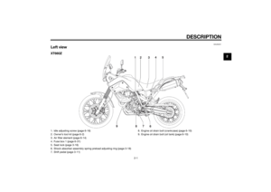
PERIODIC MAINTENANCE AND ADJUSTMENT
6-13
6
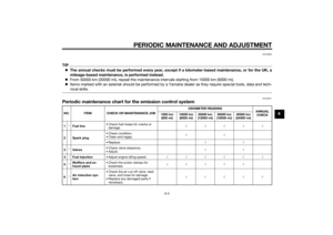
TIPBe sure to wipe off spilled oil on any
parts after the engine and exhaust sys-
tem have cooled down.NOTICE
ECA11621
In order to prevent clutch slip-
page (since the engine oil also
lubricates the clutch), do not
mix any chemical additives. Do
not use oils with a diesel speci-
fication of “CD” or oils of a high-
er quality than specified. In
addition, do not use oils labeled
“ENERGY CONSERVING II” or
higher.
Make sure that no foreign mate-
rial enters the crankcase.14. Start the engine, and then let it idle
for several minutes while checking
it for oil leakage. If oil is leaking,
immediately turn the engine off
and check for the cause.
15. Turn the engine off, and then
check the oil level and correct it if
necessary.16. Install the engine guard by install-
ing the screws.
EAU20071
CoolantThe coolant level should be checked
before each ride. In addition, the cool-
ant must be changed at the intervals
specified in the periodic maintenance
and lubrication chart.
EAU20257
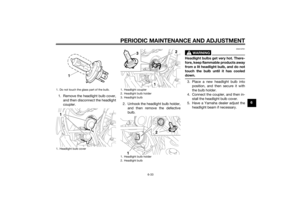
To check the coolant level
1. Place the vehicle on a level sur-
face and hold it in an upright posi-
tion.TIPThe coolant level must be
checked on a cold engine since
the level varies with engine tem-
perature.
Make sure that the vehicle is posi-
tioned straight up when checking
the coolant level. A slight tilt to the
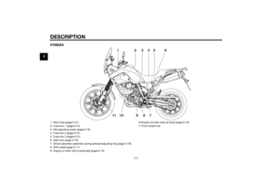
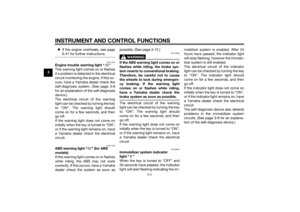
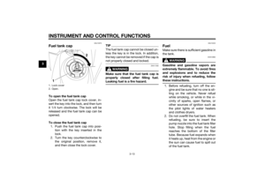
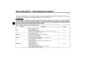
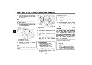
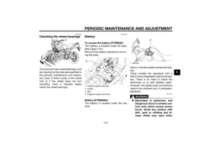
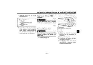
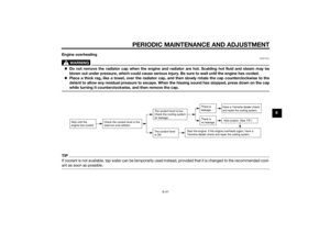
side can result in a false reading.2. Check the coolant level in the
coolant reservoir.TIPThe coolant should be between the
minimum and maximum level marks.
U2BDE1E0.book Page 13 Tuesday, December 16, 2014 5:38 PM
Page 58 of 98
, remove the
coolant reservoir cap, add coolant
to the maximum level")
PERIODIC MAINTENANCE AND ADJUSTMENT
6-14
6
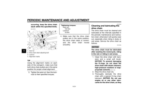
3. If the coolant is at or below the
minimum level mark, remove pan-
el A (See page 6-8.), remove the
coolant reservoir cap, add coolant
to the maximum level mark, and
then install the reservoir cap and
the panel. WARNING! Remove
only the coolant reservoir cap.
Never attempt to remove the ra-
diator cap when the engine is
hot.
[EWA15162]
NOTICE: If coolant is
not available, use distilled water
or soft tap water instead. Do not
use hard water or salt water
since it is harmful to the engine.If water has been used instead
of coolant, replace it with cool-
ant as soon as possible, other-
wise the cooling system will not
be protected against frost and
corrosion. If water has been
added to the coolant, have a
Yamaha dealer check the anti-
freeze content of the coolant as
soon as possible, otherwise the
effectiveness of the coolant will
be reduced.
[ECA10473]
EAU33032
Changing the coolant
The coolant must be changed at the in-
tervals specified in the periodic main-
tenance and lubrication chart. Have a
Yamaha dealer change the coolant.
WARNING! Never attempt to remove
the radiator cap when the engine is
hot.
[EWA10382]EAUB1483
Replacing the air filter ele-
ment and cleaning the check
hoseThe air filter element should be re-
placed at the intervals specified in the
periodic maintenance and lubrication
chart. Replace the air filter element
more frequently if you are riding in un-
usually wet or dusty areas. In addition,
the air filter check hose must be fre-
quently checked and cleaned if neces-
sary.
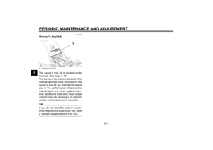
To replace the air filter element
1. Remove the seat. (See page 3-16.)
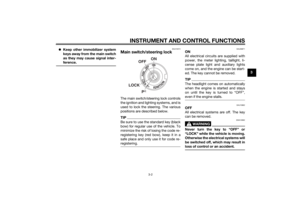
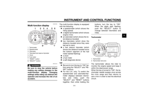
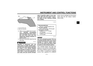
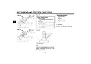
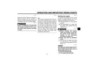
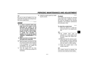
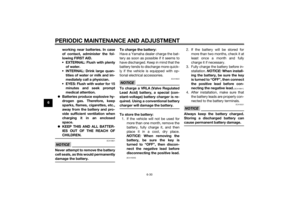
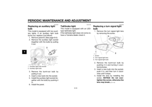
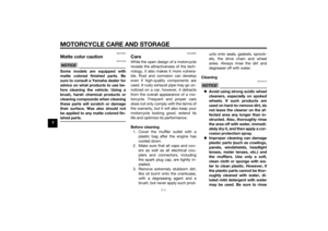
2. Remove the air filter case cover by
removing the screws.
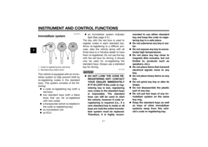
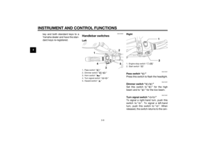
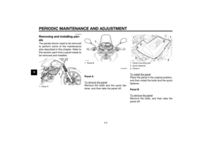
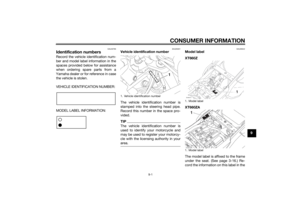
1. Coolant reservoir
2. Maximum level mark
3. Minimum level mark
4. Coolant reservoir capZAUM1264
Coolant reservoir capacity (up to
the maximum level mark):
0.50 L (0.53 US qt, 0.44 Imp.qt)
U2BDE1E0.book Page 14 Tuesday, December 16, 2014 5:38 PM
Page 59 of 98
PERIODIC MAINTENANCE AND ADJUSTMENT
6-15
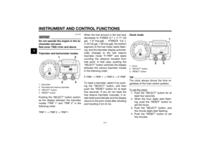
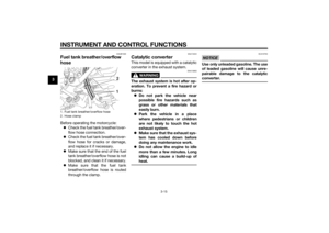
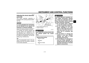
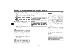
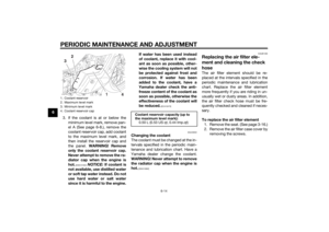
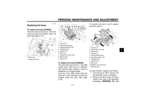
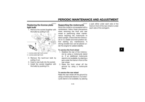
6 3. Pull the air filter element out.
4. Insert a new air filter element into
the air filter case as shown.
NOTICE: Make sure that the air
filter element is properly seated
in the air filter case. The engine
should never be operated with-
out the air filter element in-
stalled, otherwise the piston(s)
and/or cylinder(s) may become
excessively worn.
[ECA10482]
5. Install the air filter case cover by
installing the screws.
6. Install the seat.
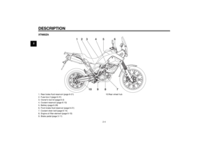
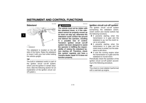
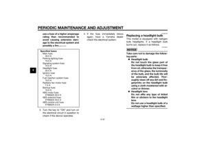
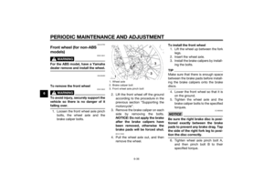
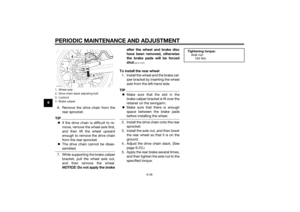
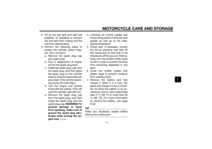
To clean the air filter check hose
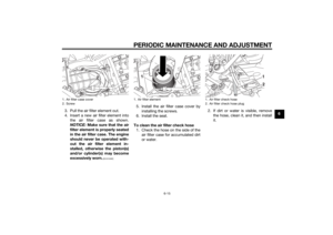
1. Check the hose on the side of the
air filter case for accumulated dirt
or water.2. If dirt or water is visible, remove
the hose, clean it, and then install
it.
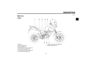
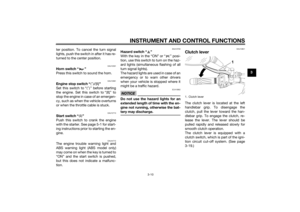
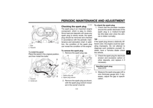
1. Air filter case cover
2. Screw
1. Air filter element
1. Air filter check hose
2. Air filter check hose plug
U2BDE1E0.book Page 15 Tuesday, December 16, 2014 5:38 PM
Page 60 of 98

PERIODIC MAINTENANCE AND ADJUSTMENT
6-16
6
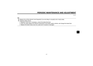
EAU21321
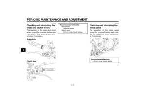
Adjusting the engine idling
speedThe engine idling speed must be
checked and, if necessary, adjusted as
follows at the intervals specified in the
periodic maintenance and lubrication
chart.
The engine should be warm before
making this adjustment.TIPThe engine is warm when it quickly re-
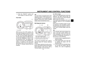
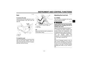
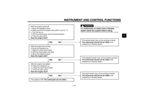
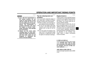
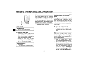
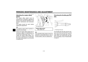
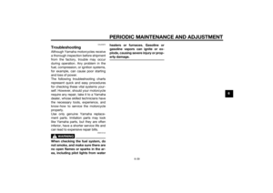
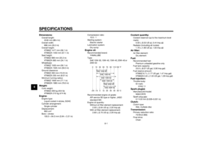
sponds to the throttle.Check the engine idling speed and, if
necessary, adjust it to specification by
turning the throttle stop screw. To in-
crease the engine idling speed, turn
the screw in direction (a). To decrease
the engine idling speed, turn the screw
in direction (b).
TIPIf the specified idling speed cannot be
obtained as described above, have a
Yamaha dealer make the adjustment.
EAU21385
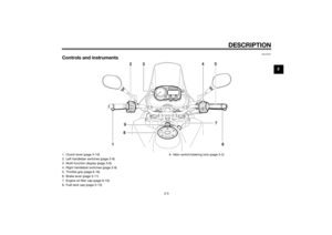
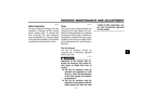
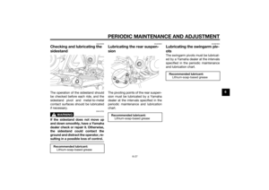
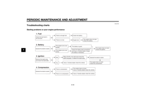
Checking the throttle grip free
playThe throttle grip free play should mea-
sure 3.0–5.0 mm (0.12–0.20 in) at the
inner edge of the throttle grip. Periodi-
cally check the throttle grip free play
and, if necessary, have a Yamaha deal-
er adjust it.
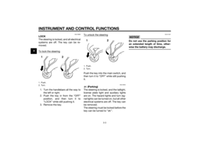
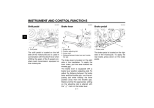
1. Idle adjusting screwEngine idling speed:
1400–1600 r/min
1. Throttle grip free play
U2BDE1E0.book Page 16 Tuesday, December 16, 2014 5:38 PM
Page 61 of 98

PERIODIC MAINTENANCE AND ADJUSTMENT
6-17
6
EAU21402
Valve clearanceThe valve clearance changes with use,
resulting in improper air-fuel mixture
and/or engine noise. To prevent this
from occurring, the valve clearance
must be adjusted by a Yamaha dealer
at the intervals specified in the periodic
maintenance and lubrication chart.
EAU21647
TiresTires are the only contact between the
vehicle and the road. Safety in all con-
ditions of riding depends on a relatively
small area of road contact. Therefore, it
is essential to maintain the tires in good
condition at all times and replace them
at the appropriate time with the speci-
fied tires.
Tire air pressure
The tire air pressure should be
checked and, if necessary, adjusted
before each ride.
WARNING
EWA10504
Operation of this vehicle with im-
proper tire pressure may cause se-
vere injury or death from loss of
control.
The tire air pressure must be
checked and adjusted on cold
tires (i.e., when the temperature
of the tires equals the ambient
temperature).
The tire air pressure must be
adjusted in accordance with the
riding speed and with the totalweight of rider, passenger, car-
go, and accessories approved
for this model.
U2BDE1E0.book Page 17 Tuesday, December 16, 2014 5:38 PM
Page 62 of 98

PERIODIC MAINTENANCE AND ADJUSTMENT
6-18
6
WARNING
EWA10512
Never overload your vehicle. Opera-
tion of an overloaded vehicle could
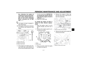
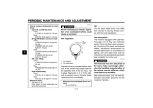
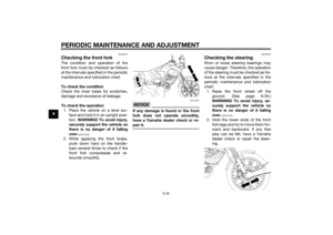
cause an accident.Tire inspection
The tires must be checked before each
ride. If the center tread depth reaches
the specified limit, if the tire has a nail
or glass fragments in it, or if the side-
wall is cracked, have a Yamaha dealer
replace the tire immediately.
TIPThe tire tread depth limits may differ
from country to country. Always com-
ply with the local regulations.Tire information
This model is equipped with tube tires.
Tires age, even if they have not been
used or have only been used occasion-
ally. Cracking of the tread and sidewall
rubber, sometimes accompanied by
carcass deformation, is an evidence of
ageing. Old and aged tires shall be
checked by tire specialists to ascertain
their suitability for further use.
WARNING
EWA10462
The front and rear tires should be of
the same make and design, other-
wise the handling characteristics of
the vehicle may be different, which
could lead to an accident.After extensive tests, only the tires list-
ed below have been approved for this
model by Yamaha.
Tire air pressure (measured on cold
tires):
Up to 90 kg (198 lbs) load:
Front:
210 kPa (2.10 kgf/cm², 30 psi)
Rear:
230 kPa (2.30 kgf/cm², 33 psi)
90 kg (198 lbs) to maximum load:
Front:
XT660Z 210 kPa (2.10 kgf/cm²,
30 psi)
XT660ZA 230 kPa (2.30
kgf/cm², 33 psi)
Rear:
XT660Z 230 kPa (2.30 kgf/cm²,
33 psi)
XT660ZA 250 kPa (2.50
kgf/cm², 36 psi)
Off-road riding:
Front:
XT660Z 200 kPa (2.00 kgf/cm²,
29 psi)
Rear:
XT660Z 200 kPa (2.00 kgf/cm²,
29 psi)
High-speed riding:
Front:
210 kPa (2.10 kgf/cm², 30 psi)
Rear:
230 kPa (2.30 kgf/cm², 33 psi)
Maximum load*:
190 kg (419 lb)
* Total weight of rider, passenger, car-
go and accessories
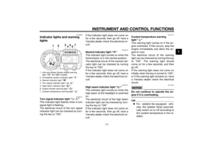
1. Tire sidewall
2. Tire tread depthMinimum tire tread depth (front and
rear):
1.6 mm (0.06 in)
U2BDE1E0.book Page 18 Tuesday, December 16, 2014 5:38 PM
Page 63 of 98

PERIODIC MAINTENANCE AND ADJUSTMENT
6-19
6
WARNING
EWA10572
Have a Yamaha dealer replace
excessively worn tires. Besides
being illegal, operating the mo-torcycle with excessively worn
tires decreases riding stability
and can lead to loss of control.
The replacement of all wheel-
and brake-related parts, includ-
ing the tires, should be left to a
Yamaha dealer, who has the
necessary professional knowl-
edge and experience.
It is not recommended to patch
a punctured tube. If unavoid-
able, however, patch the tube
very carefully and replace it as
soon as possible with a high-
quality product.
Ride at moderate speeds after
changing a tire since the tire
surface must first be “
broken
in” for it to develop its optimal
characteristics.
EAU21944
Spoke wheels
WARNING
EWA10611
The wheels on this model are not
designed for use with tubeless tires.
Do not attempt to use tubeless tires
on this model.To maximize the performance, durabil-
ity, and safe operation of your motor-
cycle, note the following points
regarding the specified wheels.
The wheel rims should be
checked for cracks, bends, warp-
age or other damage, and the
spokes for looseness or damage
before each ride. If any damage is
found, have a Yamaha dealer re-
place the wheel. Do not attempt
even the smallest repair to the
wheel. A deformed or cracked
wheel must be replaced.
The wheel should be balanced
whenever either the tire or wheel
has been changed or replaced. An
unbalanced wheel can result in
poor performance, adverse han-
dling characteristics, and a short-
ened tire life.
Front tire:
Size:
XT660Z 90/90-21 M/C 54S(MET-
ZELER)-54T(MICHELIN)
XT660ZA 90/90-21 M/C
54S(PIRELLI)
Manufacturer/model:
XT660Z METZELER/TOURANCE
FRONT
XT660ZA PIRELLI/SCORPION
TRAIL
XT660Z MICHELIN/SIRAC
Rear tire:
Size:
XT660Z 130/80-17 M/C
65S(METZELER)-65T(MICHELIN)
XT660ZA 130/80-17 M/C
65S(PIRELLI)
Manufacturer/model:
XT660Z METZELER/TOURANCE
FRONT
XT660ZA PIRELLI/SCORPION
TRAIL
XT660Z MICHELIN/SIRAC
U2BDE1E0.book Page 19 Tuesday, December 16, 2014 5:38 PM
Page 64 of 98
 as
shown. Periodically check the cl")
PERIODIC MAINTENANCE AND ADJUSTMENT
6-20
6
EAU22045
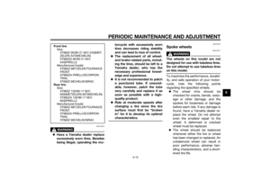
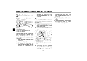
Adjusting the clutch lever free
playThe clutch lever free play should mea-
sure 10.0–15.0 mm (0.39–0.59 in) as
shown. Periodically check the clutch
lever free play and, if necessary, adjust
it as follows.
1. Slide the rubber cover back at the
clutch lever.
2. Loosen the locknut.
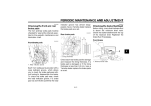
3. To increase the clutch lever free
play, turn the clutch lever free play
adjusting bolt in direction (a). Todecrease the clutch lever free
play, turn the adjusting bolt in di-
rection (b).
TIPIf the specified clutch lever free play
could be obtained as described above,
skip steps 4…7.4. Fully turn the adjusting bolt at the
clutch lever in direction (a) to loos-
en the clutch cable.
5. Loosen the locknut at the crank-
case.
6. To increase the clutch lever free
play, turn the clutch lever free play
adjusting nut in direction (a). Todecrease the clutch lever free
play, turn the adjusting nut in di-
rection (b).
7. Tighten the locknut at the crank-
case.
8. Tighten the locknut at the clutch
lever and then slide the rubber
cover to its original position.
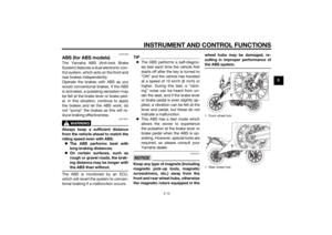
1. Locknut (clutch lever)
2. Clutch lever free play adjusting bolt
3. Clutch lever free play
1. Locknut (crankcase)
2. Clutch lever free play adjusting nut (crank-
case)
U2BDE1E0.book Page 20 Tuesday, December 16, 2014 5:38 PM