Page 33 of 98

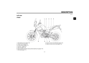
INSTRUMENT AND CONTROL FUNCTIONS
3-16
3
EAU13862
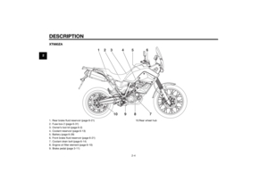
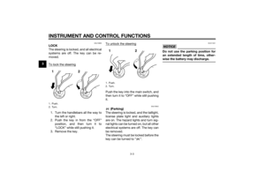
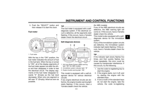
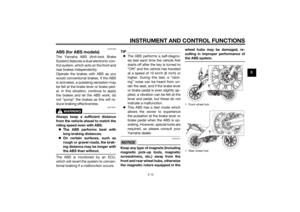
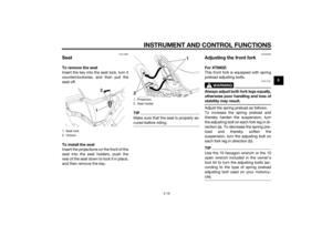
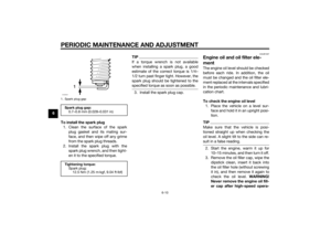
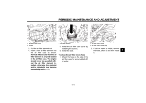
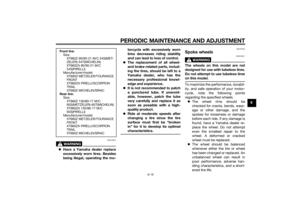
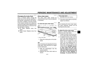
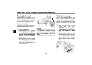
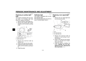
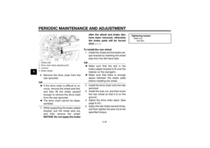
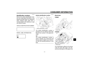
SeatTo remove the seat
Insert the key into the seat lock, turn it
counterclockwise, and then pull the
seat off.
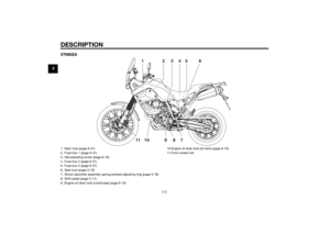
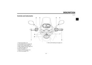
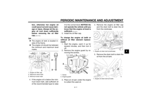
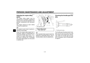
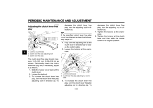
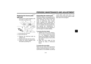
To install the seat
Insert the projections on the front of the
seat into the seat holders, push the
rear of the seat down to lock it in place,
and then remove the key.
TIPMake sure that the seat is properly se-
cured before riding.
EAUM3590
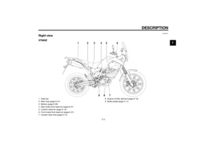
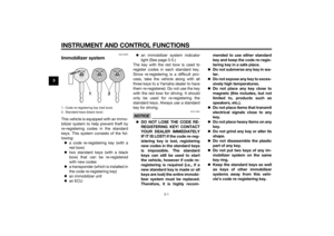
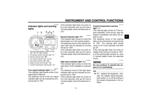
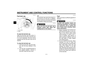
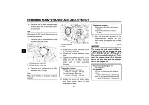
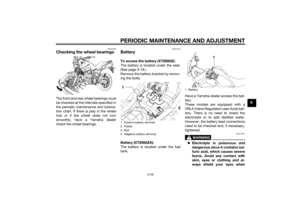
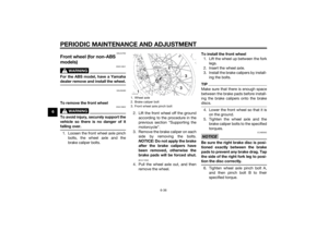
Adjusting the front forkFor XT660Z:
This front fork is equipped with spring
preload adjusting bolts.
WARNING
EWA10181
Always adjust both fork legs equally,
otherwise poor handling and loss of
stability may result.Adjust the spring preload as follows.
To increase the spring preload and
thereby harden the suspension, turn
the adjusting bolt on each fork leg in di-
rection (a). To decrease the spring pre-
load and thereby soften the
suspension, turn the adjusting bolt on
each fork leg in direction (b).TIPUse the 10 hexagon wrench or the 10
open wrench included in the owner's
tool kit to turn the adjusting bolts (ac-
cording to the type of spring preload
adjusting bolt used on your motorcy-
cle).
1. Seat lock
2. Unlock.
1. Projection
2. Seat holder
U2BDE1E0.book Page 16 Tuesday, December 16, 2014 5:38 PM
Page 34 of 98
INSTRUMENT AND CONTROL FUNCTIONS
3-17
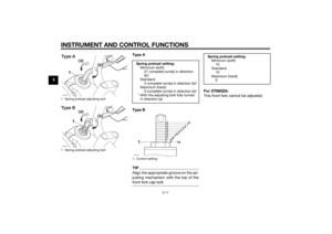
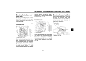
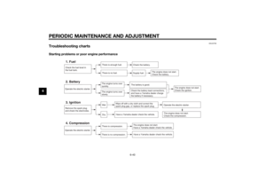
3Type A
Type B
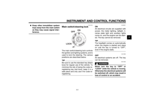
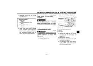
TIPAlign the appropriate groove on the ad-
justing mechanism with the top of the
front fork cap bolt.
For XT660ZA:
This front fork cannot be adjusted.
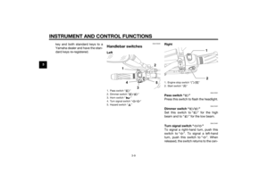
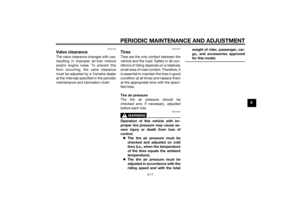
1. Spring preload adjusting bolt
1. Spring preload adjusting boltZAUM1246
(a)
(b)
Ty p e AZAUM1245
(a)
(b)
Type B
Spring preload setting:
Minimum (soft):
27 complete turn(s) in direction
(b)*
Standard:
5 complete turn(s) in direction (b)*
Maximum (hard):
0 complete turn(s) in direction (b)*
* With the adjusting bolt fully turned
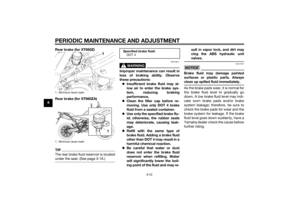
in direction (a)1. Current settingZAUM1244
76543210
89
10
Spring preload setting:
Minimum (soft):
10
Standard:
10
Maximum (hard):
0
U2BDE1E0.book Page 17 Tuesday, December 16, 2014 5:38 PM
Page 35 of 98

INSTRUMENT AND CONTROL FUNCTIONS
3-18
3
EAUB1463
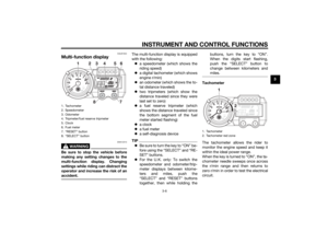
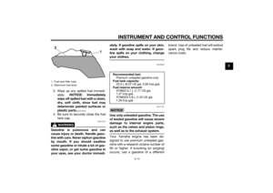
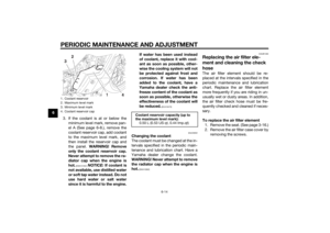
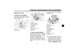
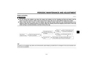
Adjusting the shock absorber
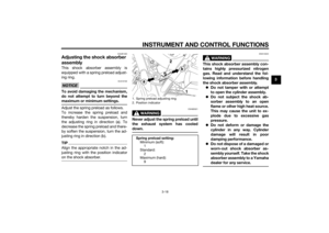
assemblyThis shock absorber assembly is
equipped with a spring preload adjust-
ing ring.NOTICE
ECA10102
To avoid damaging the mechanism,
do not attempt to turn beyond the
maximum or minimum settings.Adjust the spring preload as follows.
To increase the spring preload and
thereby harden the suspension, turn
the adjusting ring in direction (a). To
decrease the spring preload and there-
by soften the suspension, turn the ad-
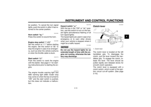
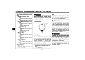
justing ring in direction (b).TIPAlign the appropriate notch in the ad-
justing ring with the position indicator
on the shock absorber.
WARNING
EWAB0021
Never adjust the spring preload until
the exhaust system has cooled
down.
WARNING
EWA10222
This shock absorber assembly con-
tains highly pressurized nitrogen
gas. Read and understand the fol-
lowing information before handling
the shock absorber assembly.
Do not tamper with or attempt
to open the cylinder assembly.
Do not subject the shock ab-
sorber assembly to an open
flame or other high heat source.
This may cause the unit to ex-
plode due to excessive gas
pressure.
Do not deform or damage the
cylinder in any way. Cylinder
damage will result in poor
damping performance.
Do not dispose of a damaged or
worn-out shock ab
sorber as-
sembly yourself. Take the shock
absorber assembly to a Yamaha
dealer for any service.
1. Spring preload adjusting ring
2. Position indicator
Spring preload setting:
Minimum (soft):
1
Standard:
2
Maximum (hard):
9
U2BDE1E0.book Page 18 Tuesday, December 16, 2014 5:38 PM
Page 36 of 98

INSTRUMENT AND CONTROL FUNCTIONS
3-19
3
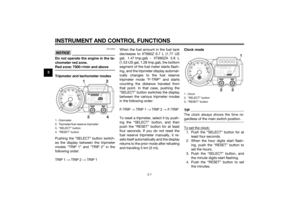
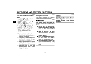
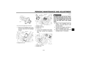
EAU15306
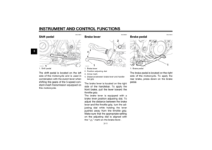
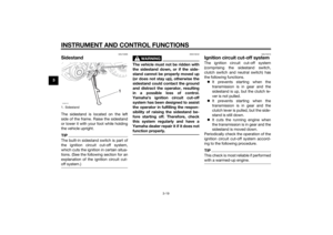
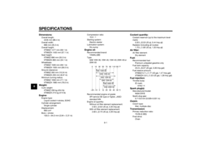
SidestandThe sidestand is located on the left
side of the frame. Raise the sidestand
or lower it with your foot while holding
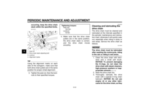
the vehicle upright.TIPThe built-in sidestand switch is part of
the ignition circuit cut-off system,
which cuts the ignition in certain situa-
tions. (See the following section for an
explanation of the ignition circuit cut-
off system.)
WARNING
EWA10242
The vehicle must not be ridden with
the sidestand down, or if the side-
stand cannot be properly moved up
(or does not stay up), otherwise the
sidestand could contact the ground
and distract the operator, resulting
in a possible loss of control.
Yamaha’s ignition circuit cut-off
system has been designed to assist
the operator in fulfilling the respon-
sibility of raising the sidestand be-
fore starting off. Therefore, check
this system regularly and have a
Yamaha dealer repair it if it does not
function properly.
EAU15315
Ignition circuit cut-off systemThe ignition circuit cut-off system
(comprising the sidestand switch,
clutch switch and neutral switch) has
the following functions.
It prevents starting when the
transmission is in gear and the
sidestand is up, but the clutch le-
ver is not pulled.
It prevents starting when the
transmission is in gear and the
clutch lever is pulled, but the side-
stand is still down.
It cuts the running engine when
the transmission is in gear and the
sidestand is moved down.
Periodically check the operation of the
ignition circuit cut-off system accord-
ing to the following procedure.TIPThis check is most reliable if performed
with a warmed-up engine.
1. SidestandZAUM1272
U2BDE1E0.book Page 19 Tuesday, December 16, 2014 5:38 PM
Page 37 of 98

INSTRUMENT AND CONTROL FUNCTIONS
3-20
3
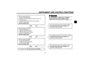
With the engine turned off:
1. Move the sidestand down.
2. Make sure that the engine stop switch is set to “
3. Turn the key on.
4. Shift the transmission into the neutral position.
5. Push the start switch.
Does the engine start?
With the engine still running:
6. Move the sidestand up.
7. Keep the clutch lever pulled.
8. Shift the transmission into gear.
9. Move the sidestand down.
Does the engine stall?
After the engine has stalled:
10. Move the sidestand up.
11. Keep the clutch lever pulled.
12. Push the start switch.
Does the engine start?
The system is OK. The motorcycle can be ridden.The neutral switch may not be working correctly.
The motorcycle should not be ridden until
checked by a Yamaha dealer.
The sidestand switch may not be working correctly.
The motorcycle should not be ridden until
checked by a Yamaha dealer.
The clutch switch may not be working correctly.
The motorcycle should not be ridden until
checked by a Yamaha dealer.
YES NO YES NO YES NO
If a malfunction is noted, have a Yamaha
dealer check the system before riding.
WARNING
”.
U2BDE1E0.book Page 20 Tuesday, December 16, 2014 5:38 PM
Page 38 of 98

FOR YOUR SAFETY – PRE-OPERATION CHECKS
4-1
4
EAU15599
Inspect your vehicle each time you use it to make sure the vehicle is in safe operating condition. Always follow the inspection
and maintenance procedures and schedules described in the Owner’s Manual.
WARNING
EWA11152
Failure to inspect or maintain the vehicle properly increases the possibility of an accident or equipment damage.
Do not operate the vehicle if you find any problem. If a problem cannot be corrected by the procedures provided in
this manual, have the vehicle inspected by a Yamaha dealer.Before using this vehicle, check the following points:
ITEM CHECKS PAGE
Fuel• Check fuel level in fuel tank.
• Refuel if necessary.
• Check fuel line for leakage.
• Check fuel tank breather hose and overflow hose for obstructions, cracks or
damage, and check hose connections.3-13, 3-15
Engine oil• Check oil level in oil tank.
• If necessary, add recommended oil to specified level.
• Check vehicle for oil leakage.6-10
Coolant• Check coolant level in reservoir.
• If necessary, add recommended coolant to specified level.
• Check cooling system for leakage.6-13
Front brake• Check operation.
• If soft or spongy, have Yamaha dealer bleed hydraulic system.
• Check lever free play.
• Adjust if necessary.
• Check brake pads for wear.
• Replace if necessary.
• Check fluid level in reservoir.
• If necessary, add specified brake fluid to specified level.
• Check hydraulic system for leakage.6-21, 6-21
U2BDE1E0.book Page 1 Tuesday, December 16, 2014 5:38 PM
Page 39 of 98

FOR YOUR SAFETY – PRE-OPERATION CHECKS
4-2
4
Rear brake• Check operation.
• If soft or spongy, have Yamaha dealer bleed hydraulic system.
• Check brake pads for wear.
• Replace if necessary.
• Check fluid level in reservoir.
• If necessary, add specified brake fluid to specified level.
• Check hydraulic system for leakage.6-21, 6-21
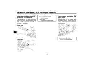
Clutch• Check operation.
• Lubricate cable if necessary.
• Check lever free play.
• Adjust if necessary.6-20
Throttle grip• Make sure that operation is smooth.
• Check throttle grip free play.
• If necessary, have Yamaha dealer adjust throttle grip free play and lubricate ca-
ble and grip housing.6-16, 6-25
Control cables• Make sure that operation is smooth.
• Lubricate if necessary.6-25
Drive chain• Check chain slack.
• Adjust if necessary.
• Check chain condition.
• Lubricate if necessary.6-23, 6-24
Wheels and tires• Check for damage.
• Check tire condition and tread depth.
• Check air pressure.
• Correct if necessary.6-17, 6-19
Brake pedal• Make sure that operation is smooth.
• Lubricate pedal pivoting point if necessary.6-26
Brake and clutch levers• Make sure that operation is smooth.
• Lubricate lever pivoting points if necessary.6-26
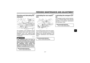
Sidestand• Make sure that operation is smooth.
• Lubricate pivot if necessary.6-27 ITEM CHECKS PAGE
U2BDE1E0.book Page 2 Tuesday, December 16, 2014 5:38 PM
Page 40 of 98
FOR YOUR SAFETY – PRE-OPERATION CHECKS
4-3
4
Chassis fasteners• Make sure that all nuts, bolts and screws are properly tightened.
• Tighten if necessary.—
Instruments, lights, signals
and switches• Check operation.
• Correct if necessary.—
Sidestand switch • Check operation of ignition circuit cut-off system.
• If system is not working correctly, have Yamaha dealer check vehicle.3-19 ITEM CHECKS PAGE
U2BDE1E0.book Page 3 Tuesday, December 16, 2014 5:38 PM