Page 49 of 94
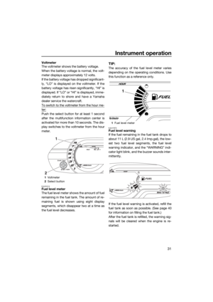
 If the engine oil level is significantly
above the maximum level mark, consult
a Yamaha deal")
Operation and handling requirements
43
engine oil level is between the minimum
and maximum level marks.
(8) If the engine oil level is significantly
above the maximum level mark, consult
a Yamaha dealer. If the engine oil level is
below the minimum level mark, slowly
add engine oil.
(9) Repeat steps 6–8 until the engine oil is at
the proper level.
(10) Securely install the oil tank filler cap and
turn it until it stops.
(11) Securely install the seat in its original po-
sition.EJU40022
Draining the bilge water
NOTICE
ECJ01302
Do not run the engine at full throttle when
bilge water remains in the engine com-
partment. The bilge water can splash into
the engine, which can result in severe
damage.
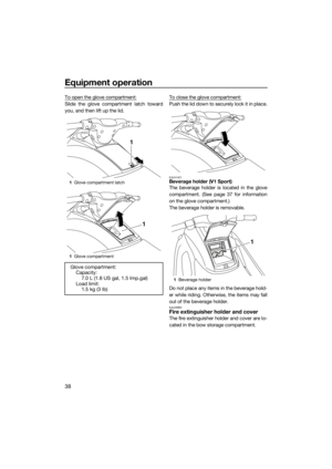
EJU40035Draining the bilge water on land
To drain the bilge water on land:
(1) Loosen the stern drain plugs and remove
them.
(2) Raise the bow of the watercraft, such as
by placing the watercraft on a slope, to
drain the bilge water from the engine
compartment.
(3) After the bilge water has drained from the
stern drain plug holes, wipe up any re-1Dipstick
2Maximum level mark
3Minimum level mark
213
1Stern drain plug
1
UF2P72E0.book Page 43 Tuesday, August 26, 2014 10:08 AM
Page 50 of 94
 Securely install the stern drain plugs by
tightening them until they stop. NOTICE:
Before inst")
Operation and handling requirements
44
maining moisture in the engine compart-
ment with a dry cloth.
(4) Securely install the stern drain plugs by
tightening them until they stop. NOTICE:
Before installing the stern drain plugs,
clean the drain plug threads and the
O-rings on the plugs to remove any
foreign materials, such as dirt or sand.
Otherwise, the stern drain plugs could
be damaged, allowing water to enter
the engine compartment. Check the
O-rings on the stern drain plugs and
make sure that the plugs are tightened
securely before launching the water-
craft. Otherwise, water may flood the
engine compartment and cause the
watercraft to submerge.
[ECJ00363]
EJU40535
Draining the bilge water on water
A small quantity of bilge water will remain in
the engine compartment even after the bilge
water is drained on water. To completely
drain the bilge water, remove the watercraft
from the water and drain the bilge water on
land.
Jet vacuum bilge draining system
While the watercraft is operating, bilge water
in the engine compartment is drawn in by the
vacuum that is generated in the jet pump and
discharged from the watercraft through the
jet thrust nozzle.
To drain the bilge water on water:
Operate the watercraft as straight as possible
and above planing speed for at least 2 min-
utes. NOTICE: Do not run the engine at full
throttle for at least 1 minute after the en-
gine has been restarted. Bilge water in the
engine compartment can splash into theengine, which can result in severe dam-
age.
[ECJ00554]
UF2P72E0.book Page 44 Tuesday, August 26, 2014 10:08 AM
Page 51 of 94
Operation and handling requirements
45
EJU33465
Transporting on a trailer
When transporting the watercraft on a trailer,
secure the tie downs to the trailer through the
bow eye and stern eyes. NOTICE: Do not at-
tach ropes or tie downs to any part of the
watercraft other than the bow eye and
stern eyes to secure the watercraft to the
trailer. Otherwise, the watercraft may be
damaged. Wrap the ropes or tie downs
with towels or rags where they touch the
body of the watercraft to avoid scratches
or damage. V1 Sport: Do not transport the
watercraft with the shift lever in the re-
verse position. Otherwise, the reverse
gate may hit an obstacle, which could
cause damage.
[ECJ00645]
UF2P72E0.book Page 45 Tuesday, August 26, 2014 10:08 AM
Page 52 of 94
First-time operation
46
EJU32786
Engine break-in
NOTICE
ECJ00432
Failure to perform the engine break-in
could result in reduced engine life or even
severe engine damage.
The engine break-in is essential to allow the
various components of the engine to wear
and polish themselves to the correct operat-
ing clearances. This ensures proper perfor-
mance and promotes longer component life.
To perform the engine break-in:
(1) Check the engine oil level. (See page 42
for information on checking the engine
oil level.)
(2) Launch the watercraft and start the en-
gine. (See page 57 for information on
starting the engine.)
(3) For the first 5 minutes, operate with the
engine at idling speed.
(4) For the next 30 minutes, operate with the
engine speed below 5000 r/min.
(5) For the next 1 hour, operate with the en-
gine speed below 6500 r/min.
After the engine break-in is complete, the wa-
tercraft can be operated normally.
UF2P72E0.book Page 46 Tuesday, August 26, 2014 10:08 AM
Page 53 of 94

Pre-operation checks
47
EJU31982
WARNING
EWJ00412
Failure to inspect or maintain the watercraft properly increases the possibility of an ac-
cident or damage to the watercraft. Do not operate the watercraft if you find any prob-
lem. If a problem cannot be corrected by the procedures provided in this manual, have
the watercraft inspected by a Yamaha dealer.
EJU41234Pre-operation checklist
Before using this watercraft, be sure to perform the checks in the following checklist.
ITEM ROUTINE PAGE
PRE-LAUNCH CHECKS
Engine compartmentVentilate the engine compartment.
Check inside the engine compartment for damage.49
Fuel systemCheck the fuel system for leakage.
Check the fuel level in the fuel tank.49
Water separatorCheck the water separator for water. 49
Engine unitCheck the exterior of the engine unit for damage. 49
Engine oil levelCheck the engine oil level. 49
Bilge waterCheck the engine compartment for bilge water. 50
BatteryCheck the battery connections and electrolyte level. 50
Steering systemCheck the steering system for proper operation. 50
Reverse system (V1 Sport)Check the reverse system for proper operation. 51
Throttle leverCheck the throttle lever for proper operation.
Check the throttle lever free play.52
Engine shut-off cord (lan-
yard)Check the engine shut-off cord (lanyard) for dam-
age.52
SwitchesCheck the start switch, engine stop switch, and en-
gine shut-off switch for proper operation.53
Storage compartmentsCheck the storage compartments for damage and
water.53
Fire extinguisher holder,
cover, and bandCheck the fire extinguisher holder, cover, and band
for damage.53
Fire extinguisherCheck the condition of the fire extinguisher. 53
Safety equipmentCheck that safety equipment meeting the applica-
ble regulations is on board.54
Hull and deckCheck the hull and deck for damage. 54
Jet intakeCheck the jet intake for damage and clogging. 54
Stern drain plugsCheck the stern drain plugs for damage and foreign
material and check that they are securely installed.54
HoodCheck that the hood is securely closed. 54
SeatCheck that the seat is securely installed. 34
UF2P72E0.book Page 47 Tuesday, August 26, 2014 10:08 AM
Page 54 of 94
Pre-operation checks
48
TIP:
To ensure safety and reliability, pre-operation checks should be made each time the water-
craft is used.
POST-LAUNCH CHECKS
Cooling water pilot outletCheck that water is discharged from the cooling
water pilot outlet while the engine is running.55
Multifunction information
centerCheck the multifunction information center for prop-
er operation.55
Engine idling speedCheck the engine idling speed. 55 ITEM ROUTINE PAGE
UF2P72E0.book Page 48 Tuesday, August 26, 2014 10:08 AM
Page 55 of 94

Pre-operation checks
49
EJU32282
Pre-operation check pointsEJU40546Pre-launch checks
Perform the pre-launch checks in the pre-op-
eration checklist while the watercraft is on
land.
To perform the pre-launch checks:
(1) Remove the seat. (See page 34 for seat
removal and installation procedures.)
(2) Perform the checks and make sure that
there are no malfunctioning items or oth-
er problems.
(3) After completing these checks, securely
install the seat in its original position.
EJU32334Engine compartment check
WARNING
EWJ00462
Failure to ventilate the engine compart-
ment could result in a fire or explosion. Do
not start the engine if there is a fuel leak.
Ventilate the engine compartment. Leave the
engine compartment open for a few minutes
to allow any fuel vapors to escape.
Make sure that there is no damage inside the
engine compartment.
EJU34215Fuel system checks
WARNING
EWJ00382
Leaking fuel can result in fire or explosion.
Check for fuel leakage regularly.
If any fuel leakage is found, the fuel sys-
tem must be repaired by a qualified me-
chanic. Improper repairs can make the
watercraft unsafe to operate.
Make sure that there is no damage, leakage,
or other problem in the fuel system.
Check:
Fuel filler cap and seal for damage
Fuel tank for damage and leakage
Fuel hoses and joints for damage and leak-
age
Fuel tank breather hose for damage and
leakage
EJU36875Fuel level check
Check the fuel level in the fuel tank.
Add fuel if necessary. (See page 40 for infor-
mation on filling the fuel tank.)
EJU32424Water separator check
Make sure that no water has collected in the
water separator. If water has collected in the
water separator, drain it. (See page 27 for in-
formation on draining the water separator.)
EJU40182Engine unit check
Check the exterior of the engine unit for dam-
age or other problem.
EJU41561Engine oil level check
Make sure that the engine oil level is between
the minimum and maximum level marks on
1Water separator
1
UF2P72E0.book Page 49 Tuesday, August 26, 2014 10:08 AM
Page 56 of 94

EJU32456Bilge water check
Make sure that no bilge water has co")
Pre-operation checks
50
the dipstick attached to the oil tank filler cap.
(See page 42 for information on checking the
engine oil level.)
EJU32456Bilge water check
Make sure that no bilge water has collected in
the engine compartment. If bilge water has
collected in the engine compartment, drain it.
(See page 43 for information on draining the
bilge water.)
EJU32485Battery checks
Make sure that the battery terminals and
breather hose are not damaged and that the
battery leads and breather hose are connect-
ed properly. WARNING! Fire or explosion
could result if the breather hose is dam-aged, obstructed, or not connected prop-
erly.
[EWJ00452]
Make sure that the electrolyte level is be-
tween the minimum and maximum level
marks. WARNING! Never operate the wa-
tercraft if the battery does not have suffi-
cient power to start the engine or if it
shows any other signs of decreased pow-
er. Loss of battery power may leave you
stranded.
[EWJ01241]
Make sure that the battery is securely held in
place.
EJU32614Steering system checks
Turn the handlebars to the right and left sev-
eral times to make sure that operation is
smooth and unrestricted throughout the
1Oil tank filler cap/Dipstick
1Dipstick
2Maximum level mark
3Minimum level mark
1
213
1Negative (–) battery terminal: Black lead
2Positive (+) battery terminal: Red lead
3Breather hose
1Maximum level mark
2Minimum level mark
12
3
UF2P72E0.book Page 50 Tuesday, August 26, 2014 10:08 AM