Page 105 of 118

Dimensions:
Length:
3560 mm (140.2 in)
Width: 1230 mm (48.4 in)
H")
Specifications
99
EJU34543
Specifications
Watercraft capacity:
Maximum people on board:3 person
Maximum load capacity: 240 kg (530 lb)
Dimensions:
Length:
3560 mm (140.2 in)
Width: 1230 mm (48.4 in)
Height: 1230 mm (48.4 in)
Dry weight: FX SVHO 378 kg (833 lb)
FX Cruiser SVHO 379 kg (836 lb)
Performance:
Maximum output (according to ISO 8665/SAE
J1228):183.9 kW@7500 r/min
Maximum fuel consumption:
77.7 L/h (20.5 US gal/h, 17.1 Imp.gal/h)
Cruising range at full throttle: 0.90 hour
Trolling speed: 1250 ±100 r/min
Engine:
Engine type:
Liquid cooled 4-stroke, DOHC
Number of cylinders: 4
Engine displacement:
1812 cm³
Bore × stroke:
86.0 × 78.0 mm (3.39 × 3.07 in)
Compression ratio: 8.5 : 1
Valve clearance-intake (cold):
0.14–0.23 mm (0.0055–0.0091 in)
Valve clearance-exhaust (cold): 0.36–0.45 mm (0.0142–0.0177 in)
Lubrication system: Wet sump
Cooling system:
Water
Starting system: Electric Ignition system:
T.C.I.
Spark plug: LFR7A
Spark plug gap:
0.8–0.9 mm (0.031–0.035 in)
Battery capacity: 12 V, 19 Ah
Charging system: Flywheel magneto
Drive unit:
Propulsion system:Jet pump
Jet pump type: Axial flow, single stage
Impeller rotation: Counterclockwise
Jet thrust nozzle angle:
24.0+24.0 °
Jet thrust nozzle trim angle: -6, -3, 0, 3, 6 °
Fuel and oil:
Recommended fuel:
Premium unleaded gasoline
Minimum octane rating (PON): 91
Minimum octane rating (RON): 95
Recommended engine oil type SAE:
SAE 10W-30, 10W-40, 20W-40, 20W-50
Recommended engine oil grade API: API SE,SF,SG,SH,SJ,SL
Fuel tank total capacity: 70 L (18.5 US gal, 15.4 Imp.gal)
Engine oil quantity with oil filter replacement:
3.6 L (3.81 US qt, 3.17 Imp.qt)
Engine oil quantity without oil filter replacement: 3.5 L (3.70 US qt, 3.08 Imp.qt)
Engine oil total quantity: 5.3 L (5.60 US qt, 4.66 Imp.qt)
UF3J71E0.book Page 99 Friday, June 27, 2014 1:50 PM
Page 106 of 118

Trouble recovery
100
EJU34562
Troubleshooting
If you have any trouble with your watercraft, use the troubleshooting chart to check for the
possible cause.
If you cannot find the cause, consult a Yamaha dealer.
EJU42783Troubleshooting chart
Confirm the possible cause and remedy, and then refer to the applicable page.
TROUBLEPOSSIBLE CAUSE REMEDYPAGE
Engine does not
start (Starter motor
does not turn over) Ya m a h a S e -
curity System
Lock mode selected Select unlock mode
27
Engine shut-
off switch Clip not in place Install clip
28
Fuse Burned out Replace fuse and
check wiring 105
Battery Run down Recharge90
Poor terminal con-
nections Tighten as required
90
Terminal corroded Clean or replace 90
Starter motor Faulty Have serviced by
Yamaha dealer —
Engine does not
start (Starter motor
turns over) Throttle lever Squeezed
Release28
Faulty Have serviced by
Yamaha dealer —
RiDE lever Squeezed Release28
Faulty Have serviced by
Yamaha dealer —
Fuel Fuel tank empty Refill as soon as pos-
sible 59
Stale or contaminat-
ed Have serviced by
Yamaha dealer
—
Fuel tank Water or dirt present Have serviced by Yamaha dealer—
Spark plug Fouled or defective Have serviced by Yamaha dealer—
Spark plug
cap Not connected or
loose Have serviced by
Yamaha dealer
—
Connected to wrong
cylinder Have serviced by
Yamaha dealer
—
Fuel injec-
tion system Fuel pump faulty Have serviced by
Yamaha dealer —
UF3J71E0.book Page 100 Friday, June 27, 2014 1:50 PM
Page 107 of 118

Trouble recovery
101
Engine runs irregu-
larly or stallsFuel Fuel tank empty Refill as soon as pos-
sible59
Stale or contaminat-
ed Have serviced by
Yamaha dealer
—
Incorrect octane
number Use correct fuel
59
Fuel tank Water or dirt present Have serviced by Yamaha dealer—
Spark plug Fouled or defective Have serviced by Yamaha dealer—
Incorrect heat range Have serviced by Yamaha dealer —
Gap incorrect Have serviced by Yamaha dealer —
Spark plug
cap Not connected or
loose Have serviced by
Yamaha dealer
—
Cracked, torn, or
damaged Have serviced by
Yamaha dealer
—
Electrical wir-
ing Loose connection Have serviced by
Yamaha dealer —
Fuel injec-
tion system Faulty or clogged in-
jectors Have serviced by
Yamaha dealer
—
Warning light or in-
dicator blinks or
comes on Fuel level
warning
Fuel tank empty Refill as soon as pos-
sible 59
Oil pressure
warning Oil pressure dropped Have serviced by
Yamaha dealer 44
Engine over-
heat warning Jet intake clogged Clean
103
Check en-
gine warning Faulty sensors Have serviced by
Yamaha dealer 45
TROUBLE POSSIBLE CAUSE REMEDY PAGE
UF3J71E0.book Page 101 Friday, June 27, 2014 1:50 PM
Page 108 of 118

Trouble recovery
102
Watercraft slow or
loses powerWatercraft
operation
modeLow RPM Mode acti-
vated
Deactivate Low RPM
Mode 36
Cavitation Jet intake clogged Clean 103 Impeller damaged or
worn Have serviced by
Yamaha dealer
103
Engine over-
heat warning Engine speed reduc-
tion control activated Clean jet intake and
cool engine
44
Oil pressure
warning Engine speed reduc-
tion control activated Add oil
44
Spark plug Fouled or defective Have serviced by Yamaha dealer—
Incorrect heat range Have serviced by Yamaha dealer —
Gap incorrect Have serviced by Yamaha dealer —
Spark plug
cap Not connected or
loose Have serviced by
Yamaha dealer
—
Electrical wir-
ing Loose connection Have serviced by
Yamaha dealer —
Fuel Stale or contaminat- ed Have serviced by
Yamaha dealer
—
Incorrect octane
number Use correct fuel
59
Air filter Clogged Have serviced by Yamaha dealer—
Oil buildup Have serviced by Yamaha dealer —
Throttle lever Faulty Have serviced by Yamaha dealer—
TROUBLE POSSIBLE CAUSE REMEDY PAGE
UF3J71E0.book Page 102 Friday, June 27, 2014 1:50 PM
Page 109 of 118

Trouble recovery
103
EJU34625
Emergency proceduresEJU34635Cleaning the jet intake and impeller
WARNING
EWJ00783
Before attempting to remove weeds or de-
bris from the jet intake or impeller area,
shut the engine off and remove the clip
from the engine shut-off switch. Severe in-
jury or death could result from coming in
contact with the rotating parts of the jet
pump.
If weeds or debris gets caught in the jet intake
or impeller, cavitation can occur, causing jet
thrust to decrease even though engine speed
rises. If this condition is allowed to continue,
the engine will overheat and may seize.
NOTICE: If weeds or debris gets caught in
the jet intake, do not operate the water-
craft above trolling speed until they have
been removed.
[ECJ00654]
If there is any sign that the jet intake or impel-
ler is clogged with weeds or debris, return to
shore and check the intake and impeller. Al- ways stop the engine before beaching the
watercraft.
(1) Place a suitable clean cloth or carpeting
underneath the watercraft to protect it
from abrasions and scratches. Turn the
watercraft on its side as shown.
NOTICE: Always turn the watercraft
over onto its port (left) side. When
turning the watercraft on its side, sup-
port the bow so that the handlebars
are not bent or damaged.
[ECJ00662]
UF3J71E0.book Page 103 Friday, June 27, 2014 1:50 PM
Page 110 of 118
 Remove any weeds or debris fromaround the jet intake, drive shaft, impel-
ler, jet pump housing, and jet thrust noz-
zle.
If debris is difficult to remove, consult a
Yamaha de")
Trouble recovery
104
(2) Remove any weeds or debris fromaround the jet intake, drive shaft, impel-
ler, jet pump housing, and jet thrust noz-
zle.
If debris is difficult to remove, consult a
Yamaha dealer.
EJU43471Raising the reverse gate
If the RiDE system malfunctions and the re-
verse gate remains in the lowered position,
the watercraft will not be able to move for-
ward.
After raising the reverse gate so that the wa-
tercraft can move forward, immediately re-
turn to shore and have a Yamaha dealer
service the watercraft.
To raise the reverse gate:
(1) Stop the engine and remove the clip from the engine shut-off switch.
(2) Enter the water and move to the rear of the watercraft.
(3) Slide the shift rod joint toward the bow, and then disconnect the shift rod joint
from the ball joint. (4) Raise the reverse gate to the forward po-
sition.
TIP:
While the shift rod is disconnected, the re-
verse gate will not move to the neutral po-
sition or reverse position even if the RiDE
lever is squeezed.
If the RiDE lever is squeezed while the shift
rod is disconnected, the watercraft will
move forward.
EJU34642Jumping the battery
If the watercraft battery has run down, the en-
gine can be started using a 12-volt booster
battery and jumper cables.
EJU34664Connecting the jumper cables
WARNING
EWJ01251
To avoid battery explosion and serious
damage to the electrical system:
Do not reverse the polarity of the jumper
cables when connecting to the batter-
ies.
Do not connect the negative (–) jumper
cable to the negative (–) terminal of the
watercraft battery.
Do not touch the positive (+) jumper ca-
ble to the negative (–) jumper cable.
1Shift rod joint
2 Ball joint
1 2
1
Reverse gate
2 Forward position
2
1
UF3J71E0.book Page 104 Friday, June 27, 2014 1:50 PM
Page 111 of 118
Trouble recovery
105
(1) Connect the positive (+) jumper cable tothe positive (+) battery terminals of both
batteries.
(2) Connect one end of the negative (–) jumper cable to the negative (–) battery
terminal of the booster battery.
(3) Connect the other end of the negative (–) jumper cable to an engine hanger.
(4) Start the engine, and then disconnect the jumper cables by reversing the steps
above. (See page 28 for information on
starting the engine.)EJU43481Replacing the fuses
If a fuse is blown, replace it with the proper
fuse.
To replace a fuse:
(1) Remove the seats. (See page 50 for seatremoval and installation procedures.)
1Negative (–) jumper cable
2 Booster battery
3 Positive (+) jumper cable
4 Engine hanger
1
4
3
2
1Good fuse
2 Blown fuse
1 Good fuse
2 Blown fuse
2
1
2
1
UF3J71E0.book Page 105 Friday, June 27, 2014 1:50 PM
Page 112 of 118
Trouble recovery
106
(2) Remove the electrical box cover.
(3) While pushing both sides of the fuse boxcover inward, pull the cover toward the
bow and remove it.
(4) When replacing the SCU fuse, remove the screws, and then remove the fuse. Install the spare fuse, and then tighten
the screws.
(5) When replacing a fuse other than the SCU fuse, remove the fuse using the
fuse puller. Install a spare fuse of the
proper amperage. WARNING! Do not
use fuses of a different amperage than
recommended. Substitution with a
fuse that has an improper rating can
cause extensive electrical system
damage and possible fire.
[EWJ00803]
1 Electrical box cover
1 Fuse box cover
1
1
1Electronic throttle valve fuse
2 Fuel pump fuse
3 Main relay drive fuse
4 Main fuse
5 Spare fuse
6 Fuse puller
7 Battery fuse
8 Screw
9 SCU fuse (BCU fuse)
10 Bilge pump fuse
11 Security system fuse
1
5
23 4 5 6 7
8
9
8
1110
UF3J71E0.book Page 106 Friday, June 27, 2014 1:50 PM
 1
1 2
2 3
3 4
4 5
5 6
6 7
7 8
8 9
9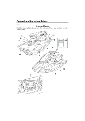 10
10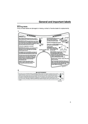 11
11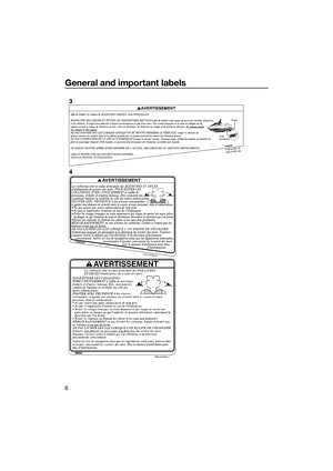 12
12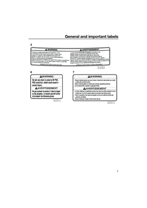 13
13 14
14 15
15 16
16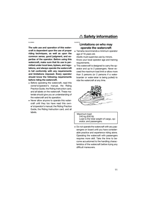 17
17 18
18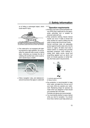 19
19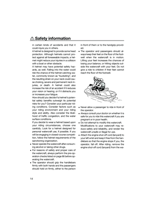 20
20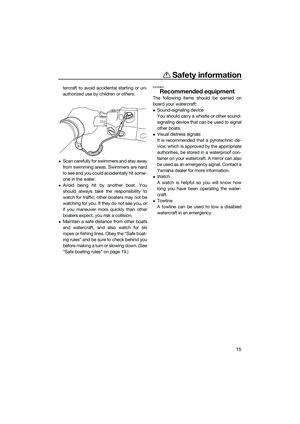 21
21 22
22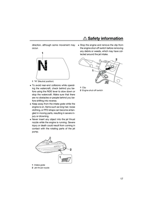 23
23 24
24 25
25 26
26 27
27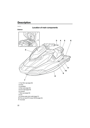 28
28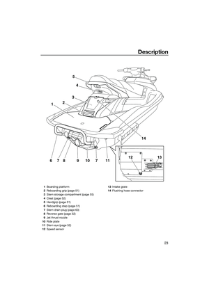 29
29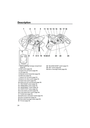 30
30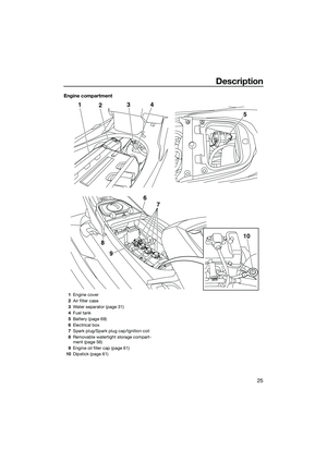 31
31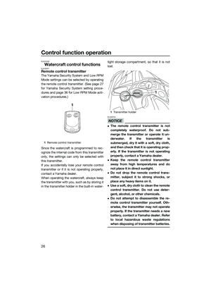 32
32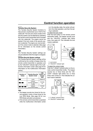 33
33 34
34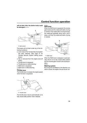 35
35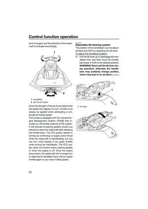 36
36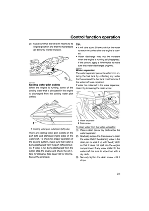 37
37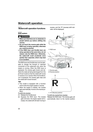 38
38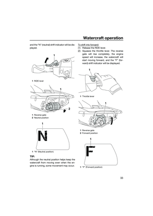 39
39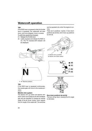 40
40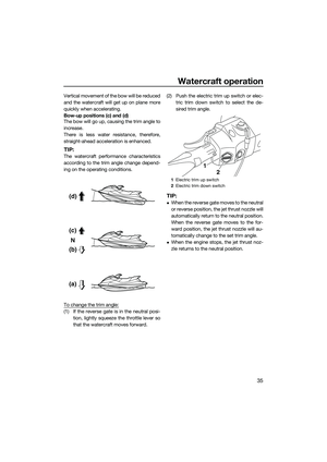 41
41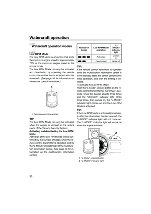 42
42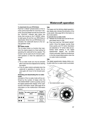 43
43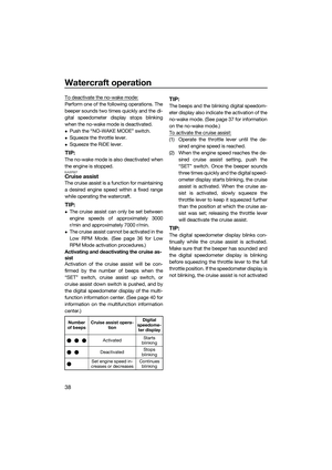 44
44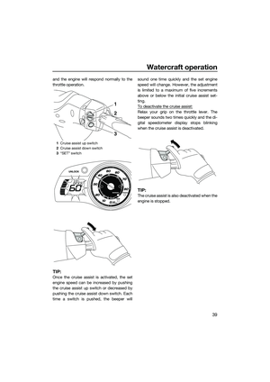 45
45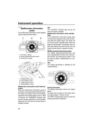 46
46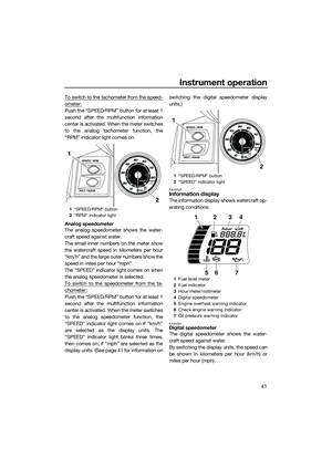 47
47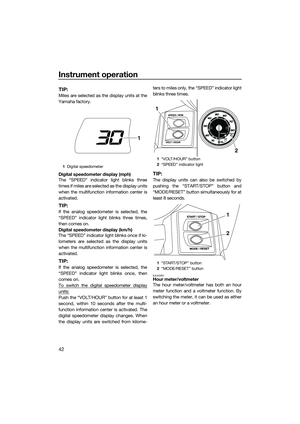 48
48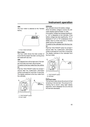 49
49 50
50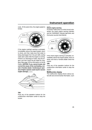 51
51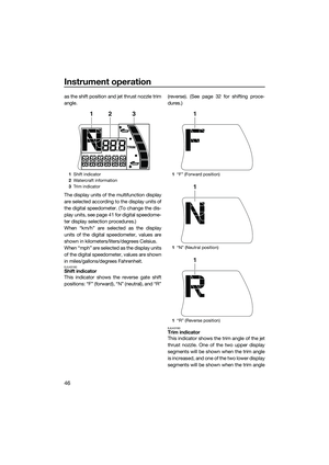 52
52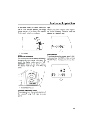 53
53 54
54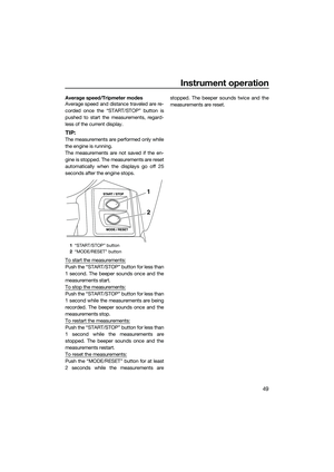 55
55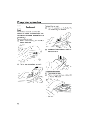 56
56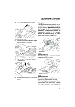 57
57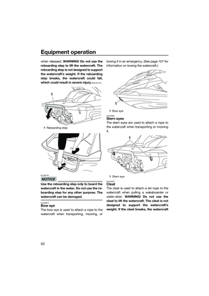 58
58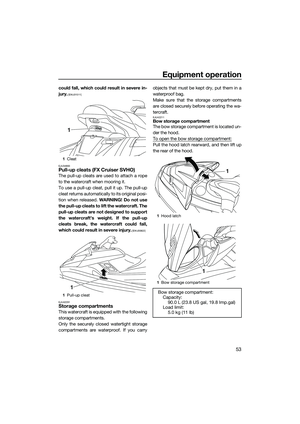 59
59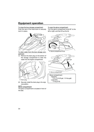 60
60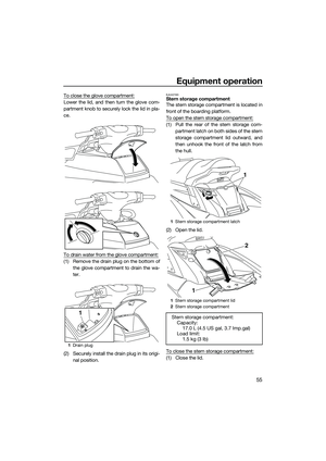 61
61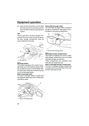 62
62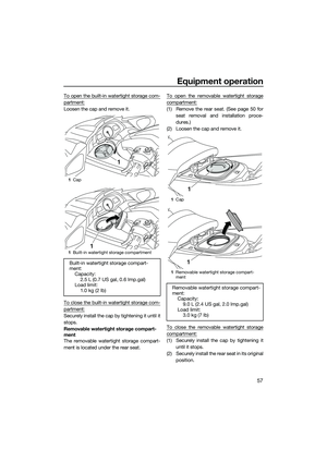 63
63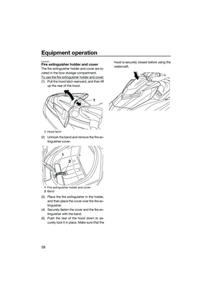 64
64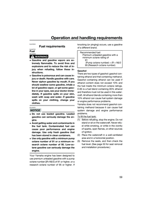 65
65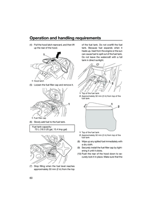 66
66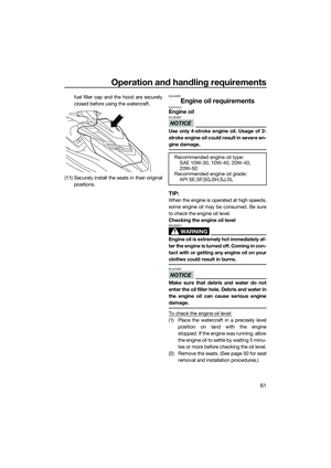 67
67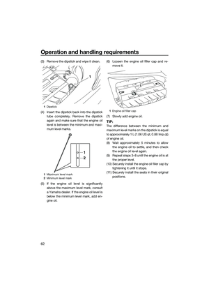 68
68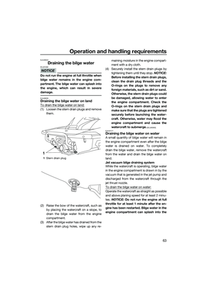 69
69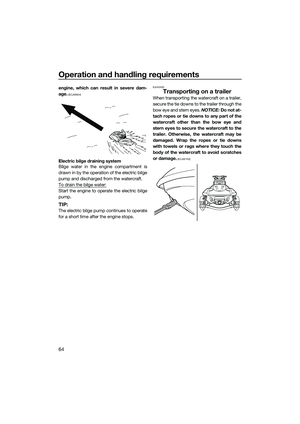 70
70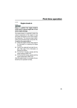 71
71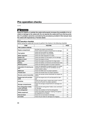 72
72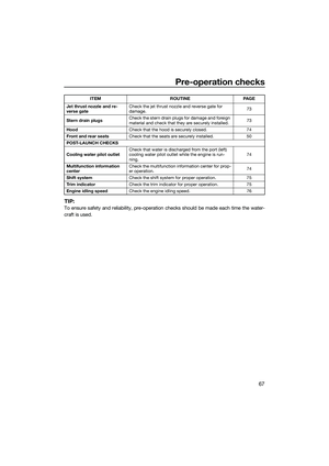 73
73 74
74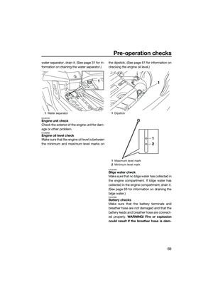 75
75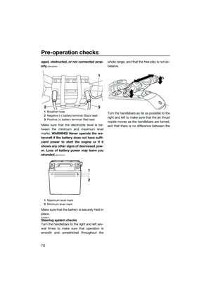 76
76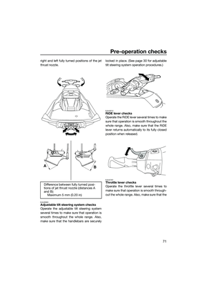 77
77 78
78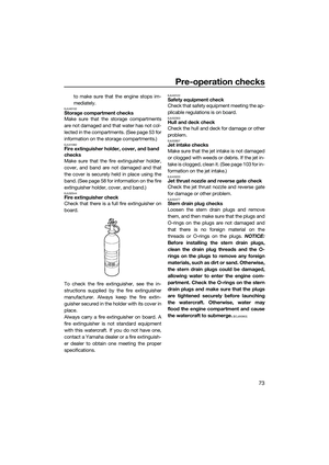 79
79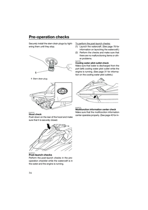 80
80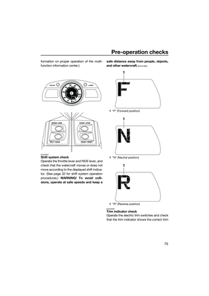 81
81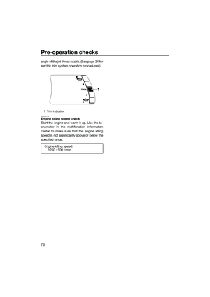 82
82 83
83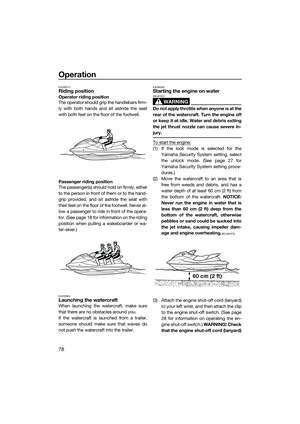 84
84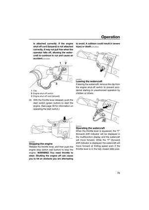 85
85 86
86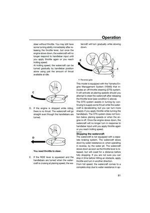 87
87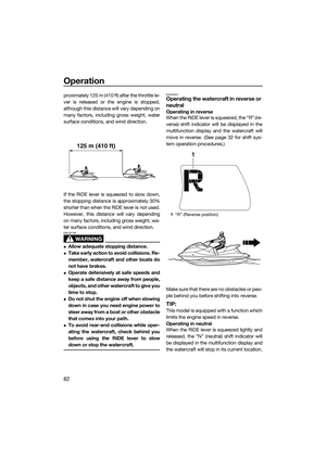 88
88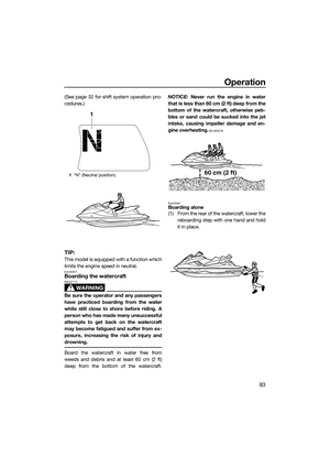 89
89 90
90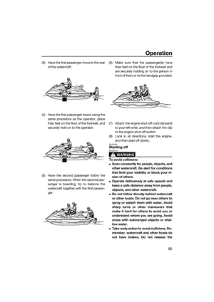 91
91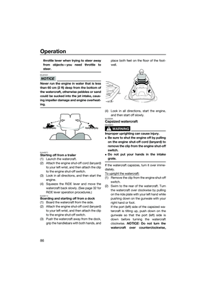 92
92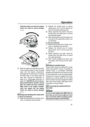 93
93 94
94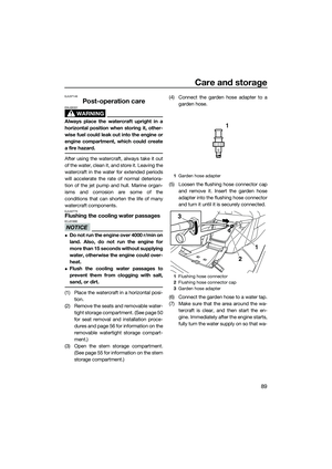 95
95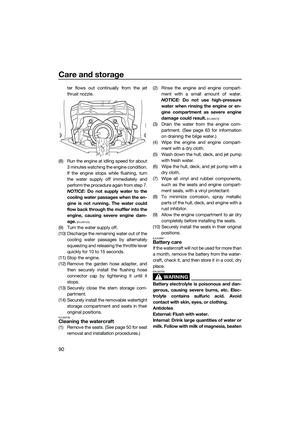 96
96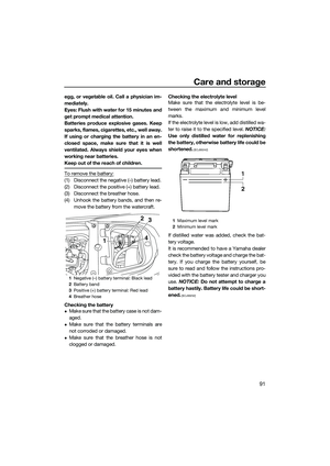 97
97 98
98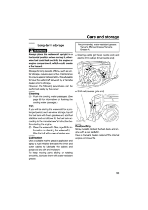 99
99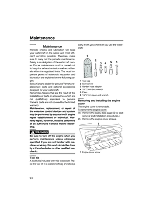 100
100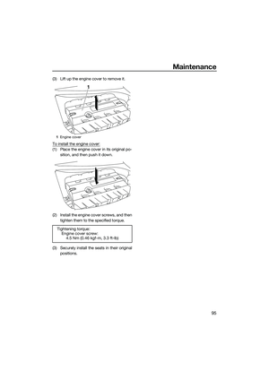 101
101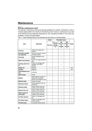 102
102 103
103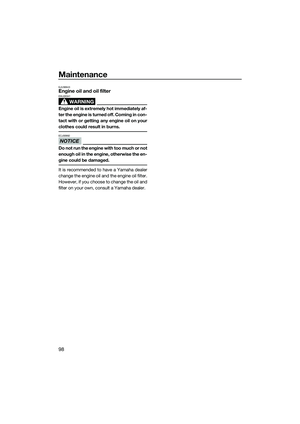 104
104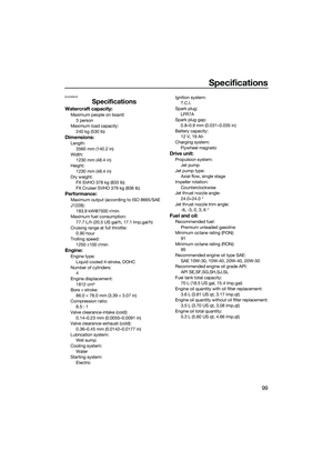 105
105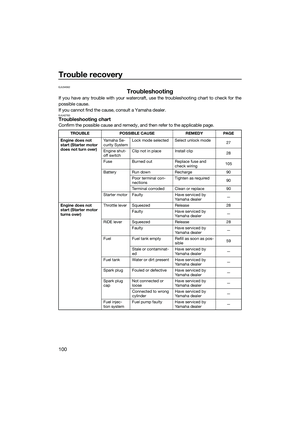 106
106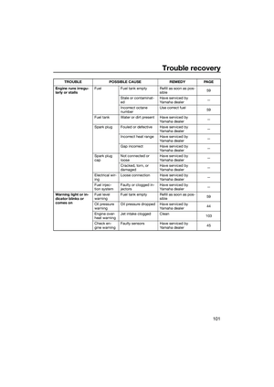 107
107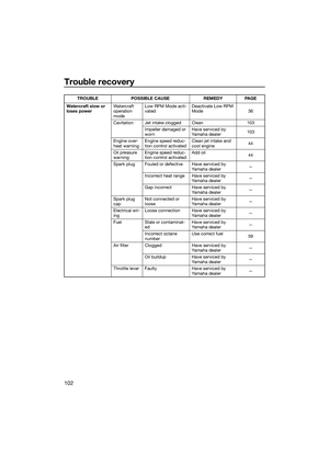 108
108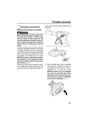 109
109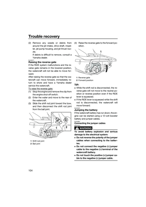 110
110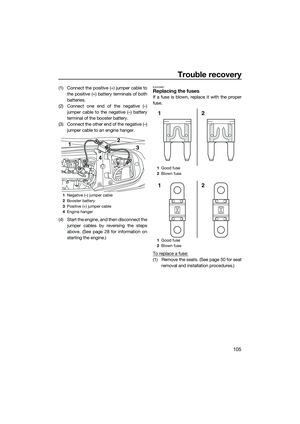 111
111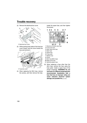 112
112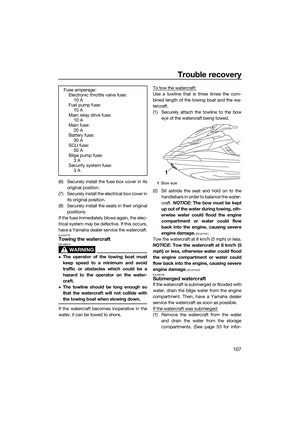 113
113 114
114 115
115 116
116 117
117 Connect the positive (+) jumper cable tothe positive (+) battery terminals of both
batteries.
(2) Connect one end of the negative (–) jumper cable to the negative (–) batt")
 Remove the electrical box cover.
(3) While pushing both sides of the fuse boxcover inward, pull the cover toward the
bow and remove it.
(4) When replacing the SCU fuse, remove")