Page 185 of 348

WARNING!
•The HBA system can’t overrule the natural laws of
physics, and can’t increase the grip available ac-
cording to the condition of the road.
•The")
Hydraulic Brake Assistant System (HBA)
WARNING!
•The HBA system can’t overrule the natural laws of
physics, and can’t increase the grip available ac-
cording to the condition of the road.
•The HBA system cannot prevent accidents, includ-
ing those due to excessive speed on corners, driv-
ing on low-grip surfaces or aquaplaning.
•The capability of the HBA system must never be
tested irresponsibly and dangerously, in such a
way as to compromise the safety of the driver, the
other occupants of the car or any other road user.
The HBA system is designed to improve the car ’s braking
capacity during emergency braking. The system detects
emergency braking by monitoring the speed and force
with which the brake pedal is pressed, and consequentlyapplies the optimal brake pressure. This can reduce the
braking distance, the HBA system therefore completes
the ABS.
Maximum assistance from the HBA system is obtained
pressing the brake pedal very quickly. In addition, the
brake pedal should be pressed continuously during
braking, avoiding intermittent presses, to get the most
out of the system.
Do not reduce pressure on the brake pedal until braking
is no longer necessary.
The HBA system is deactivated when the brake pedal is
released.
5
STARTING AND OPERATING 183
Page 186 of 348
Electronic Q2 System (E-Q2)
The�Electronic Q2�system intervenes during accelera-
tion on corners, braking the inner drive wheel and thus
increasing the traction of the outer wheel (which bears
more of the car ’s weight): the torque is thus distributed
optimally between the drive wheels in accordance with
the driving conditions and road surface, permitting par-
ticularly effective, sporty driving.
Ready Alert Brake System (RAB)
This function activates automatically if the accelerator
pedal is released rapidly, reducing the brake pad travel
(both at front and back), with the aim of preparing the
braking system and enhancing its responsiveness, thus
reducing the stopping distance in the event of subse-
quent braking.
TIRE SAFETY INFORMATION
Tire Markings
1 — U.S. DOT Safety Standards
Code (TIN)4 — Maximum Load
2 — Size Designation 5 — Maximum Pressure
3 — Service Description 6 — Treadwear, Traction and
Temperature Grades 184 STARTING AND OPERATING
Page 189 of 348
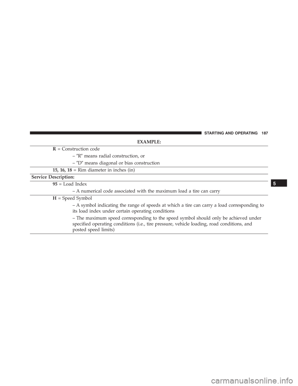
EXAMPLE:
R= Construction code
–�R�means radial construction, or
–�D�means diagonal or bias construction
15, 16, 18= Rim diameter in inches (in)
Service Description:
95= Load Index
– A numerical code associated with the maximum load a tire can carry
H= Speed Symbol
– A symbol indicating the range of speeds at which a tire can carry a load corresponding to
its load index under certain operating conditions
– The maximum speed corresponding to the speed symbol should only be achieved under
specified operating conditions (i.e., tire pressure, vehicle loading, road conditions, and
posted speed limits)
5
STARTING AND OPERATING 187
Page 199 of 348

•Unequal tire pressures from one side of the vehicle
to the other can cause the vehicle to drift to the
right or left.
•Always drive with each tire inflated to the recom-
mende")
WARNING!(Continued)
•Unequal tire pressures from one side of the vehicle
to the other can cause the vehicle to drift to the
right or left.
•Always drive with each tire inflated to the recom-
mended cold tire inflation pressure.
Both under-inflation and over-inflation affect the stability
of the vehicle and can produce a feeling of sluggish
response or over responsiveness in the steering.
NOTE:
•Unequal tire pressures from side to side may cause
erratic and unpredictable steering response.
•Unequal tire pressure from side to side may cause the
vehicle to drift left or right.
Economy
Underinflated tires will increase tire rolling resistance
resulting in higher fuel consumption.
Tread Wear
Improper cold tire inflation pressures can cause abnor-
mal wear patterns and reduced tread life, resulting in the
need for earlier tire replacement.
Ride Comfort And Vehicle Stability
Proper tire inflation contributes to a comfortable ride.
Over-inflation produces a jarring and uncomfortable
ride.
Tire Inflation Pressures
The proper cold tire inflation pressure is listed on the
driver’s side B-Pillar or rear edge of the driver’s side
door.
5
STARTING AND OPERATING 197
Page 200 of 348

At least once a month:
•Check and adjust tire pressure with a good quality
pocket-type pressure gauge. Do not make a visual
judgement when determining proper inflation. Tires
may look properly inflated even when they are under-
inflated.
•Inspect tires for signs of tire wear or visible damage.
CAUTION!
After inspecting or adjusting the tire pressure, al-
ways reinstall the valve stem cap. This will prevent
moisture and dirt from entering the valve stem,
which could damage the valve stem.
Inflation pressures specified on the placard are always
“cold tire inflation pressure.” Cold tire inflation pressure
is defined as the tire pressure after the vehicle has not
been driven for at least three hours, or driven less than 1mile (1.6 km) after sitting for a minimum of three hours.
The cold tire inflation pressure must not exceed the
maximum inflation pressure molded into the tire side-
wall.
Check tire pressures more often if subject to a wide range
of outdoor temperatures, as tire pressures vary with
temperature changes.
Tire pressures change by approximately 1 psi (7 kPa) per
12°F (7°C) of air temperature change. Keep this in mind
when checking tire pressure inside a garage, especially in
the winter.
Example: If garage temperature = 68°F (20°C) and the
outside temperature = 32°F (0°C) then the cold tire
inflation pressure should be increased by 3 psi (21 kPa),
which equals 1 psi (7 kPa) for every 12°F (7°C) for this
outside temperature condition.
198 STARTING AND OPERATING
Page 211 of 348

CAUTION!
To avoid damage to your vehicle or tires, observe the
following precautions:
•Because of restricted traction device clearance be-
tween tires and other suspension components, it is
important that only traction devices in good condi-
tion are used. Broken devices can cause serious
damage. Stop the vehicle immediately if noise
occurs that could indicate device breakage. Remove
the damaged parts of the device before further use.
•Install device as tightly as possible and then re-
tighten after driving about ½ mile (0.8 km).
•Do not exceed 30 mph (48 km/h).
•Drive cautiously and avoid severe turns and large
bumps, especially with a loaded vehicle.
•Do not drive for a prolonged period on dry pave-
ment.
(Continued)
CAUTION!(Continued)
•Observe the traction device manufacturer ’s instruc-
tions on the method of installation, operating
speed, and conditions for use. Always use the
suggested operating speed of the device manufac-
turer ’s if it is less than 30 mph (48 km/h).
•Do not use traction devices on a compact spare tire.
TIRE ROTATION RECOMMENDATIONS
Due to tire design and size, tire rotations on this vehicle
are not possible.
5
STARTING AND OPERATING 209
Page 214 of 348

•After inspecting or adjusting the tire pressure,
always reinstall the valve stem cap. This will
prevent moisture and dirt from entering the valve
stem, which could damage the Ti")
CAUTION!(Continued)
•After inspecting or adjusting the tire pressure,
always reinstall the valve stem cap. This will
prevent moisture and dirt from entering the valve
stem, which could damage the Tire Pressure Moni-
toring Sensor.
NOTE:
•The TPMS is not intended to replace normal tire care
and maintenance, or to provide warning of a tire
failure or condition.
•The TPMS should not be used as a tire pressure gauge
while adjusting your tire pressure.
•Driving on a significantly under-inflated tire causes
the tire to overheat and can lead to tire failure.Under-inflation also reduces fuel efficiency and tire
tread life, and may affect the vehicle’s handling and
stopping ability.
•The TPMS is not a substitute for proper tire mainte-
nance, and it is the driver ’s responsibility to maintain
correct tire pressure using an accurate tire gauge, even
if under-inflation has not reached the level to trigger
illumination of the Tire Pressure Monitoring Telltale
Light.
•Seasonal temperature changes will affect tire pressure,
and the TPMS will monitor the actual tire pressure in
the tire.
Base System
This is the TPMS warning indicator located in the
instrument cluster.
212 STARTING AND OPERATING
Page 218 of 348

Reformulated Gasoline
Many areas of the country require the use of cleaner
burning gasoline referred to as “Reformulated Gasoline.”
Reformulated gasoline contain oxygenates and are spe-
cifically blended to reduce vehicle emissions and im-
prove air quality.
The manufacturer supports the use of reformulated gaso-
line. Properly blended reformulated gasoline will pro-
vide excellent performance and durability of engine and
fuel system components.
Gasoline/Oxygenate Blends
Some fuel suppliers blend unleaded gasoline with oxy-
genates such as 10% Ethanol, Methyl Tert-Butyl Ether
(MTBE), and Ethyl Tret-Butyl Ether (ETBE). Oxygenates
are required in some areas of the country during the
winter months to reduce carbon monoxide emissions.Fuels blended with these oxygenates may be used in
your vehicle.
CAUTION!
Do not use gasoline containing Methanol or E-85
Ethanol. Use of these blends may result in starting
and drivability problems and may damage critical
fuel system components.
Problems that result from using methanol/gasoline
blends are not the responsibility of the manufacturer.
While MTBE is an oxygenate made from Methanol, it
does not have the negative effects of Methanol.
MMT In Gasoline
Methylcyclopentadienyl Manganese Tricarbonyl (MMT)
is a manganese-containing metallic additive that is
blended into some gasoline to increase octane. Gasoline
blended with MMT provides no performance advantage
216 STARTING AND OPERATING