Page 100 of 348
If several obstacles are detected by the sensors, only the
nearest one is considered.
Indications On Display — If Equipped
When the sensors are activated, the screen appears on the
display.Obstacle presence and distance information is therefore
provided both by the acoustic signal and the instrument
panel display.
The system indicates a detected obstacle by displaying an
arc in one or more positions according to the distance of
the obstacle and its position in relation to the car.
If an obstacle is detected in the rear central area, the
display shows all the arcs in the rear central area, up to
the one that corresponds to the position of the obstacle
itself.
The signal is similar for obstacles in the rear left or right
area.
The arc that corresponds to the position of the obstacle
will flash.
The color on the display depends on the distance from
and position of the obstacle.
Parking Sensors Screen
98 UNDERSTANDING THE FEATURES OF YOUR VEHICLE
Page 102 of 348

NOTE:The sensor must be free from mud, dirt snow or
ice in order for the system to operate correctly. Be careful
not to scratch or damage the sensors while cleaning them.
Avoid using dry, rough or hard cloths. The sensors must be
washed using clean water, with the addition of car sham-
poo if necessary. When using special washing equipment
such as high pressure jets or steam cleaning, clean the
sensors very quickly keeping the jet more than 4 in (10 cm)
away. Also, do not apply stickers to the sensors.
CAUTION!
•The Parking Sensor system is only a parking aid
and it is unable to recognize every obstacle, includ-
ing small obstacles. Parking curbs might be tem-
porarily detected or not detected at all. Obstacles
located above or below the sensors will not be
detected when they are in close proximity
(Continued)
CAUTION!(Continued)
•The vehicle must be driven slowly when using the
Parking Sensor system in order to be able to stop in
time when an obstacle is detected. It is recom-
mended that the driver looks over his/her shoulder
when using the Parking Sensor system.
WARNING!
Drivers must be careful when backing up even when
using the Parking Sensor system. Always check care-
fully behind your vehicle, and be sure to check for
pedestrians, animals, other vehicles, obstructions, or
blind spots before backing up. You are responsible
for the safety of your surroundings and must con-
tinue to pay attention while backing up. Failure to do
so can result in serious injury or death.
100 UNDERSTANDING THE FEATURES OF YOUR VEHICLE
Page 114 of 348
,
should be checked monthly when cold and
inflated to the inflati")
INSTRUMENT CLUSTER DESCRIPTIONS
1. Tire Pressure Monitoring Telltale Light — If Equipped
Each tire, including the spare (if provided),
should be checked monthly when cold and
inflated to the inflation pressure recommended
by the vehicle manufacturer on the vehicle
placard or tire inflation pressure label. (If your vehicle
has tires of a different size than the size indicated on the
vehicle placard or tire inflation pressure label, you should
determine the proper tire inflation pressure for those
tires.)
As an added safety feature, your vehicle has been
equipped with a Tire Pressure Monitoring System
(TPMS) that illuminates a low tire pressure telltale when
one or more of your tires is significantly under-inflated.
Accordingly, when the low tire pressure telltale illumi-
nates, you should stop and check your tires as soon as
possible, and inflate them to the proper pressure. Drivingon a significantly under-inflated tire causes the tire to
overheat and can lead to tire failure. Under-inflation also
reduces fuel efficiency and tire tread life, and may affect
the vehicle’s handling and stopping ability.
Please note that the TPMS is not a substitute for proper
tire maintenance, and it is the driver ’s responsibility to
maintain correct tire pressure, even if under-inflation has
not reached the level to trigger illumination of the TPMS
low tire pressure telltale.
Your vehicle has also been equipped with a TPMS
malfunction indicator to indicate when the system is not
operating properly. The TPMS malfunction indicator is
combined with the low tire pressure telltale. When the
system detects a malfunction, the telltale will flash for
approximately one minute and then remain continuously
illuminated. This sequence will continue upon subse-
quent vehicle start-ups as long as the malfunction exists.
When the malfunction indicator is illuminated, the sys-
tem may not be able to detect or signal low tire pressure
112 UNDERSTANDING YOUR INSTRUMENT PANEL
Page 120 of 348

18. Fuel Door Reminder
The arrow in this symbol is a reminder that the
Fuel Filler Door is located on the right side of
the vehicle.
19. Trip Odometer
This area of the cluster displays the total distance trav-
eled since the last Trip reset.
20. Electronic Throttle Control (ETC) Light
This light informs you of a problem with the
Electronic Throttle Control (ETC) system. The
light will come on when the ignition is first
turned ON and remain on briefly as a bulb
check. If the light does not come on during starting, have
the system checked by an authorized dealer.
If a problem is detected, the light will come on while the
engine is running. Cycle the ignition key when the
vehicle has completely stopped and the gear selector isplaced in the 1st position. The light should turn off.
If the light remains lit with the engine running, your
vehicle will usually be drivable. However, see an autho-
rized dealer for service as soon as possible. If the light is
flashing when the engine is running, immediate service is
required. You may experience reduced performance, an
elevated/rough idle or engine stall and your vehicle may
require towing.
21. Speedometer
Indicates vehicle speed.
22. “Alfa DNA” Driving Mode Indicator
This area of the cluster displays which driving mode the
vehicle is currently in. A letter (d, n, or a) corresponding
to the active driving mode (dynamic or race, natural, all
weather) and a dedicated message is shown on the
display.
118 UNDERSTANDING YOUR INSTRUMENT PANEL
Page 142 of 348
Values Displayed
Indications On Display
Each time a value is selected, the following information is
shown in the EVIC:
•“Trip A” or “Trip B” location(s)
•Name, value and unit of measure of the selected value
(e.g.�Range 520 mi�).
After a few seconds, the name of the selected value is
replaced by the corresponding icon.
Range
This indicates the distance which may be traveled with
the fuel remaining in the tank, assuming that driving
conditions will not change. The message “----” will
appear on the display in the following cases:
140 UNDERSTANDING YOUR INSTRUMENT PANEL
Page 144 of 348

•No. 2 tweeter speakers with 38 mm diameter and No.
2 mid-woofer speakers with 130 mm diameter, fitted
on the doors.
For further information on radio functions and use, refer
to the dedicated Supplement attached to the On-Board
Documentation.
RADIO OPERATION AND MOBILE PHONES
Under certain conditions, the mobile phone being on in
your vehicle can cause erratic or noisy performance from
your radio. This condition may be lessened or eliminated
by relocating the mobile phone antenna. This condition is
not harmful to the radio. If your radio performance does
not satisfactorily “clear” by the repositioning of the
antenna, it is recommended that the radio volume be
turned down or off during mobile phone operation.
General Information
This device complies with Part 15 of the FCC rules and
RSS 210 of Industry Canada. Operation is subject to the
following conditions:
•Changes or modifications not expressly approved by
the party responsible for compliance could void the
user’s authority to operate the equipment.
•This device may not cause harmful interference.
•This device must accept any interference received,
including interference that may cause undesired op-
eration.
142 UNDERSTANDING YOUR INSTRUMENT PANEL
Page 156 of 348

STARTING PROCEDURES
Before starting your vehicle, adjust your seat, adjust both
inside and outside mirrors, and fasten your seat belts.
WARNING!
•Never leave children alone in a vehicle, or with
access to an unlocked vehicle.
•Allowing children to be in a vehicle unattended is
dangerous for a number of reasons. A child or
others could be seriously or fatally injured. Chil-
dren should be warned not to touch the parking
brake, brake pedal or the transmission gear selec-
tor.
•Do not leave the Key Fob in or near the vehicle (or
in a location accessible to children). A child could
operate power windows, other controls, or move
the vehicle.
Automatic Transmission
To start the engine press the brake pedal: the system
engages NEUTRAL (N) automatically.
After the starting procedure, FIRST (1st) gear or RE-
VERSE (R) can be engaged.
Irrespective of the mode selected (AUTO/MANUAL), to
engage FIRST (1st) gear or REVERSE (R), it is necessary
to press the brake pedal and press the 1 button on the
transmission control panel (or the�+�steering wheel
stalk) to engage FIRST (1st) gear or the R button to
engage REVERSE (R).
When FIRST (1st) gear is engaged, the system sets itself to
AUTO mode.
NEUTRAL (N) can be engaged again by pressing the N
button with the brake pedal pressed.
154 STARTING AND OPERATING
Page 160 of 348
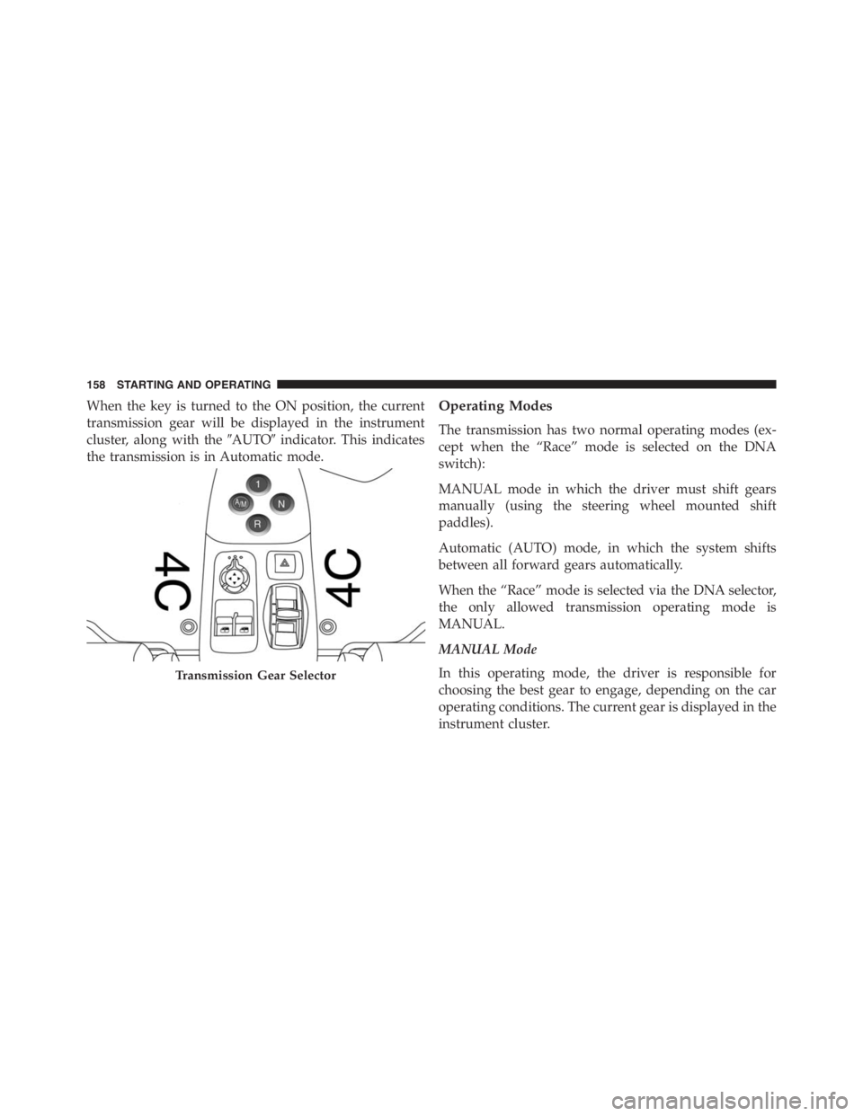
When the key is turned to the ON position, the current
transmission gear will be displayed in the instrument
cluster, along with the�AUTO�indicator. This indicates
the transmission is in Automatic mode.Operating Modes
The transmission has two normal operating modes (ex-
cept when the “Race” mode is selected on the DNA
switch):
MANUAL mode in which the driver must shift gears
manually (using the steering wheel mounted shift
paddles).
Automatic (AUTO) mode, in which the system shifts
between all forward gears automatically.
When the “Race” mode is selected via the DNA selector,
the only allowed transmission operating mode is
MANUAL.
MANUAL Mode
In this operating mode, the driver is responsible for
choosing the best gear to engage, depending on the car
operating conditions. The current gear is displayed in the
instrument cluster.
Transmission Gear Selector
158 STARTING AND OPERATING


•Name, value and unit of measure of")