2015 MERCEDES-BENZ SLS AMG GT COUPE service indicator
[x] Cancel search: service indicatorPage 8 of 290
Notes on using dual-zone auto-
matic climate control .....................1
08
Overview of systems ..................... .106
Problems with cooling with air
dehumidification ............................ 110
Problem with the rear window
defroster ........................................ 113
Refrigerant ..................................... 284
Refrigerant filling capacity ............. 285
Setting the aird istribution ............. 110
Setting the airflow ......................... 111
Setting the airv ents ..................... .113
Setting the temperature ................ 110
Switching air-recirculation mode
on/off ............................................ 113
Switching on/off ........................... 108
Switching the MONO function on/
off ................................................. .111
Switching the rear window
defroster on/off ............................ 112
Cockpit
Overview .......................................... 26
see Instrument cluster
COMAND
see separate operating instructions
Combination switch ............................ 98
Consumptio nstatistic s(on -board
computer) .......................................... 153
Convenience closing feature .............. 77
Convenience opening feature ............ 76
see Opening/closing the sid ewin-
dow s(all)
Coolant
Display message ............................ 177
Coolan t(en gine)
Checking the leve l......................... 221
Important safety notes .................. 285
Temperature (on-board computer) .. 160
Cooling
see Climate control
Copyright ............................................. 24
Crash-responsive emergency light-
ing ....................................................... 100
Cruis econtrol
Cruise control leve r....................... 139
Deactivating ................................... 140
Display message ............................ 180 Driving system ............................... 138
Function/notes ............................
.138
Important safety notes .................. 138
LIM indicator lamp ......................... 139
Setting aspee d.............................. 139
Storing and maintaining current
spee d............................................. 139
Cup holder
Center console .............................. 202
Important safety notes .................. 202
Curb weight
see Technical data
Customer Assistanc eCenter (CAC) ... 23
Customer Relations Department ....... 23 D
Dashboard see Cockpit
Data
see Technical data
Daytime runnin glamps
Display message ............................ 175
Switching on/off (on-board com-
puter) ............................................. 158
Switching on/off (switch) ................ 96
Declarations of conformity ................. 22
Delaye dswitch-off
Exterior lighting (on-board com-
puter) ............................................. 158
Interior lighting .............................. 159
Diagnostic sconnection ..................... .22
Digital speedometer .........................152
Display (cleaning instructions) ........229
Display messages ASSYST PLUS service interva ldis-
pla y................................................ 222
Calling up (on-board computer) ..... 164
Driving system s............................. 180
Engine ............................................ 177
Genera lnotes ................................ 162
Hiding (on-board computer) ........... 164
Lights ............................................. 173
Safety systems .............................. 170
Service interva ldisplay .................. 222
SmartKey ....................................... 185
Tires ............................................... 182
Vehicl e........................................... 184 6
Index
Page 17 of 290
DOT (Department of Transporta-
tion) (definition) ............................. 268
GAW
R(GrossA xle Weight Rating)
(definition) .................................... .268
GVW (Gross Vehicle Weight) (def-
inition) .......................................... .268
GVW R(Gross Vehicle Weight Rat-
ing) (definition) .............................. 269
Important safety notes .................. 250
Increase dvehicle weight due to
optional equipment (definition) ...... 268
Kilopascal (kPa )(definition) ........... 269
Labeling (overview )........................ 264
Loa dbearing index (definition) ...... 270
Loa dindex ..................................... 266
Loa dindex (definition) ................... 269
Maximu mloaded vehicleweight
(definition) ..................................... 269
Maximu mloadona tire (definition) .. 269
Maximu mpermissibl etire pres-
sure (definition) ............................. 269
Maximu mtire load ......................... 267
Maximu mtire load (definition) ....... 269
Optiona lequipment weight (defi-
nition) ............................................ 269
PSI (pounds pe rsquare inch )(de f-
inition) ........................................... 269
Replacing ....................................... 270
Service life ..................................... 252
Sidewal l(de finition) ....................... 269
Speed rating (definition) ................ 268
Storing ........................................... 271
Structure and characteristics
(definition) ..................................... 268
Technica ldata. .............................. 277
Temperature .................................. 264
TIN (Tire Identification Number)
(definition) ..................................... 270
Tire bead (definition) ...................... 269
Tire pressure (definition) ................ 269
Tire pressures (recommended )...... 268
Tire size (data )............................... 275
Tire size designation, load-bearing capacity, speed rating .................... 264
Tire trea d....................................... 251
Tire trea d(definition) ..................... 269
Tota lloa dlim it (definition) ............. 270
Tractio n......................................... 263 Tractio
n(definition) ....................... 270
Tread wear ..................................... 263
Uniform Tire Quality Grading
Standard s...................................... 263
Uniform Tire Quality Grading
Standard s(de finition) .................... 268
Wea rindicator (definition) ............. 270
Wheel rim (definition) .................... 268
see Fla ttire
Top Tether ............................................ 53
Tow-away alarm .................................. 59
Towing Important safety guideline s........... 244
Installing the towing ey e................ 245
Removing the towing ey e............... 245
With the rea raxler aised ................ 245
Towin gaway
With both axles on the ground ....... 246
Transmission
Driving tip s.................................... 124
Selector lever ................................ 121
Shift rang e..................................... 127
Transmissio nposition display ......... 123
Transmissio npositions .................... 123
Transporting the vehicle .................. 246
Trim piece s(clea ning instructions) .. 230
Trip computer (on-board computer) .. 153
Trip odometer Calling up ....................................... 152
Trunk
Emergency release .......................... 74
Important safety guideline s............. 72
Locking separatel y........................... 74
Opening (automatically from
inside ).............................................. 73
Trunk lid
Displa ymessage ............................ 184
Opening/closing ........................ 72, 73
Opening dimensions ...................... 286
Trunk load (maximum) ...................... 286
see Technical data
Turn signal (display message) ......... 174
Turn signals Switching on/of f.............................. 98
Type identificatio nplate
see Vehicl eide ntification plate Index
15
Page 207 of 290
The mbrac
esystem To adjus
tthe volum eduring an mbrace call,
procee dasfollows:
X Press the 0081or0082 button on the mul-
tifunctio nsteering wheel.
or
X Use the volum econtroller of COMAND.
The mbrace system provides various serv-
ices, e.g.:
R Automatic and manua lemergency call
R Roadside Assistance call
R MB Info call
USA only: yo ucan find informatio nand a
description of al lavailable features under
"Owners Online "athttp://www.mbusa.com.
Self-diagnosi softhe system After yo
uhaves witched on the ignition, the
system carrie soutas elf-diagnosis.
Am alfunctio ninthe system ha sbeen
detecte difone of the following conditions
occurs:
R The indicator lamp in the SOS button does
not come on during the system self-test.
R The indicator lamp in the 0052Roadside
Assistance button does not light up during
self-diagnosi softhe system.
R The indicator lamp in the 00D9MB Info call
button does not light up during self-diag-
nosi soft he system.
R The indicator lamp in one or mor eofthe
following buttons continue stolight up red
after the system self-diagnosis:
- SOS button
- 0052 Roadside Assistance cal lbutton
- 00D9 MB Info cal lbutton
R the Tele Tele Aid
AidInoperative
Inoperative orTele
Tele Aid
Aid
Not Activated
Not Activated message appearsinthe
multifunctio ndisplay after the system self-
diagnosis.
If am alfunctio nisindicated as outlined
above ,the system ma ynot operate as expected. In the event of an emergency
,help
will have to be summoned by othe rmeans.
Hav ethe system checked at the nearest
authorize dMercedes-Benz Center or contact
the following service hotlines:
R USA: Mercedes-Benz Customer Assistance
Center at 1-800-FOR-MERCedes
(1-800-367-6372) or 1-866-990-9007
R Canada: Customer Service at
1-888-923-8367
Emergenc ycall Important safety notes
! Yo
um usth aveal icens eagreement to
activate the mbrace service. Ensure that
your system is activated and ready for use, and press the 00D9MB Info cal lbutton to
register. If one of these step sisnot carried
out, it ma ynot be possibl etoactivate the
system.
If yo uhaveq uest ions abou tthe activation,
contact one of the following telephone hot- lines:
R USA: Mercedes-Benz Customer Assis-
tance cente rat1 -800-FOR-MERCedes
(1-800-367-6372) or 1-866-990-9007
R Canada: Customer Service at
1-888-923-8367
General notes
An emergency cal lisdialedautomaticall yifan
ai rb ag or Emergency Tensioning Device is
triggered.
i Yo
uc anno tend an automaticall ytrig-
gered emergency cal lyoursel f.
An emergency cal lcan also be initiated man-
ually.
As soo nasthe emergency cal lhas been ini-
tiated ,the indicator lamp in the SOS button
flashes. The ConnectingCall
Connectin gCall message
appear sinthe multifunctio ndisplay.
The audi ooutpu tism uted. Features
205Stowag eand featur es Z
Page 209 of 290
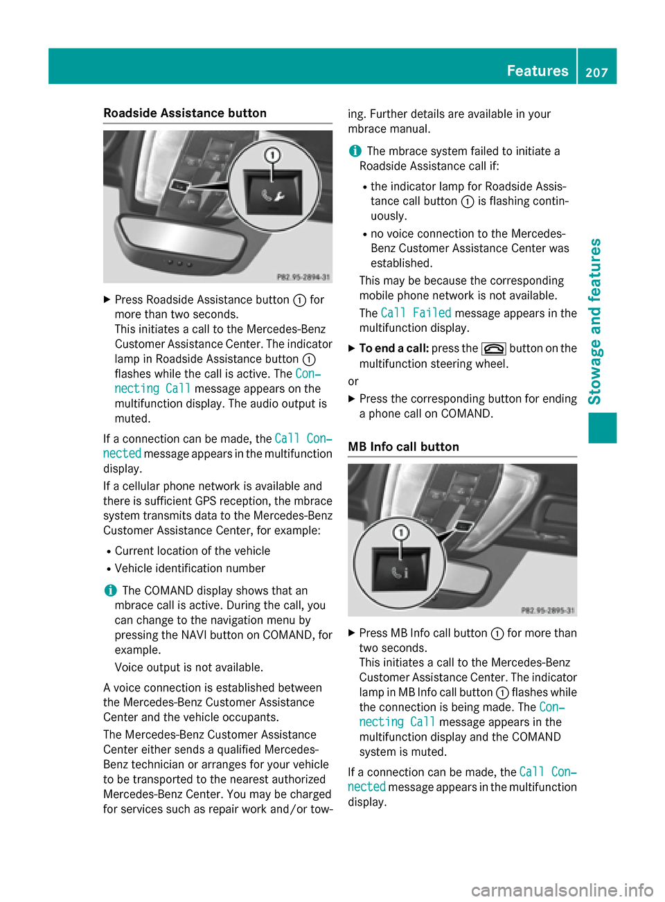
Roadside Assistanc
ebutton X
Press Roadsid eAssistance button 0043for
more than two seconds.
Thi sinitiates acalltot he Mercedes-Benz
Custome rAssistance Center. The indicator
lamp in Roadsid eAssistance button 0043
flashe swhile the cal lisactive. The Con‐
Con‐
necting Call
necting Call message appears on the
multifunction display .The audi ooutpu tis
muted.
If ac onnection can be made, the Call Con‐
Call Con‐
nected nected message appears in the multifunction
display.
If ac ellula rphone network is available and
there is sufficient GP Sreception, the mbrace
system transmits data to the Mercedes-Benz Custome rAssistance Center, for example:
R Current location of the vehicle
R Vehicl eide ntification number
i The COMAND display shows that an
mbrace cal lisactive. During the call, you
can change to the navigation menu by
pressing the NAVI button on COMAND, for
example.
Voice outpu tisn ot available.
Av oice connection is established between
the Mercedes-Benz Custome rAssistance
Center and the vehicl eoccupants.
The Mercedes-Benz Custome rAssistance
Center either send saqualified Mercedes-
Benz technicia norarranges for your vehicle
to be transported to the neares tauthorized
Mercedes-Benz Center. Yo umay be charged
for service ssuchasr epairworka nd/or tow- ing. Further detail
sare available in your
mbrace manual.
i The mbrace system faile dtoinitiate a
Roadsid eAssistance cal lif:
R the indicator lamp for Roadsid eAssis-
tance cal lbutton 0043is flashing contin-
uously.
R no voice connection to the Mercedes-
Benz Custome rAssistance Center was
established.
Thi sm ay be because the corresponding
mobil ephone network is not available.
The Call Failed
Call Failed message appears in the
multifunction display.
X To en dacall:press the 0076button on the
multifunction steering wheel.
or
X Press the corresponding button for ending
ap hone cal lonCOMAND.
MB Info cal lbutton X
Press MB Info cal lbutton 0043for more than
two seconds.
Thi sinitiates acalltot he Mercedes-Benz
Custome rAssistance Center. The indicator
lamp in MB Info cal lbutton 0043flashe swhile
the connection is being made. The Con‐ Con‐
necting Call
necting Call message appears in the
multifunction display and the COMAND
system is muted.
If ac onnection can be made, the Call Con‐ Call Con‐
nected
nected message appears in the multifunction
display. Features
207Stowage and features Z
Page 210 of 290
If
ac ellular phone network is available and
there is sufficient GPS reception, the mbrace
system transmits data to the Mercedes-Benz Customer Assistance Center, for example:
R Current location of the vehicle
R Vehicle identification number
i The COMAND display shows that an
mbrace call is active. During the call, you
can change to the navigation menu by
pressing the NAVI button on COMAND, for
example.
Voice outputisn ot available.
Av oice connection is established between
the Mercedes-Benz Customer Assistance
Center and the vehicle occupants. You can
obtain information on how to operate your
vehicle's systems, on the location of the near- est authorized Mercedes-Benz Center, and on
further products and services offered by
Mercedes-Benz USA.
USA only: you can find further information on
the mbrace system under "Owners Online" at
http://www.mbusa.com.
i The mbrace system failed to initiate an
MB Info call if:
R the indicator lamp in MB Info call but-
ton 0043is flashing continuously.
R no voice connection to the Mercedes-
Benz Customer Assistance Center was
established.
This may be because the corresponding
mobilep hone network is not available.
The Call Failed
Call Failed messageappears in the
multifunction display.
X To end acall: press the 0076button on the
multifunction steering wheel.
or
X Press the corresponding button for ending
ap hone call on COMAND. Call priority When service calls are active, e.g. Roadside
Assistance or MB Info calls,ane mergency
call can still be initiated .Inthis case, an emer-
gency call willt ake priority and override all
other active calls.
The indicator lamp of the respective button
flashes until the call is ended. An emergency call can only be terminated by the Mercedes-
Benz Customer Assistance Center.
All other calls can be ended by pressing:
R the 0076 button on the multifunction steer-
ing wheel
R or the corresponding COMAND button for
ending atelephone call
i If an mbrace call is initiated
,audio output
is muted. The mobilep hone is no longer
connected to COMAND. If you must use
yourm obilephone, we recommend that
you do this only when the vehicle is sta-
tionary and in asafe location.
Downloading destination sinCOMAND Downloadin
gdestinations
i Information on the components and oper-
ating principles of COMAND can be found
in the separate COMAND operating instruc-
tions.
This service is part of the mbrace PLUS Pack-
age and cannot be purchased separately.
i You can only use the Destination Down-
loadf unction if the vehicle is equippedw ith
an avigation system.
Destination Download gives you access to a
data bank with over 15 million Points of Inter-
est (POIs) .These can be downloaded on the
navigation system in yourv ehicle.Ifyou know
the destination, the address can be down-
loaded. Alternatively ,you can obtain the loca-
tion of Points of Interest (POIs)/important
destinations in the vicinity.
You are prompted to confirm route guidance
to the address entered. 208
FeaturesStowagea
nd features
Page 241 of 290
In the event of
ashort circuit or asimilar inci-
dent, contact aqualifieds pecialist workshop
immediately.Don ot drive any further. You
shouldh ave all work involving the battery car-
ried out at aqualifieds pecialist workshop. G
WARNING
Electrostatic build-up can leadtot he creation
of sparks, which could ignite the highlye xplo-
sive gases of abattery. There is arisk of an
explosion.
Before handling the battery, touch the vehicle body to remove any existing electrostatic
build-up.
The highlyf lammable gas mixture forms when
charging the battery as wellasw hen jump-
starting.
Alwaysm ake sure that neither you nor the
battery is electrostatically charged. Abuild-
up of electrostatic charge can be caused, for
example:
R by wearing clothing made from synthetic
fibers
R due to friction betwee nclothing and seats
R if you push or pullt he battery across the
carpet or other synthetic materials
R if you wipet he battery with acloth G
WARNING
During the charging process, abattery produ-
ces hydrogen gas. If ashort circuit occurs or
sparks are created, the hydrogen gas can
ignite. There is arisk of an explosion.
R Make sure that the positive terminal of a
connected battery does not come into con- tact with vehicle parts.
R Never place metal objects or tools on abat-
tery.
R It is important that you observe the descri-
bed order of the battery terminals when
connecting and disconnecting abattery.
R When jump-starting, make sure that the
battery polesw ith identical polarity are
connected. R
It is particularly important to observe the
describe dorder when connecting and dis-
connecting the jumper cables.
R Never connect or disconnect the battery
terminals whilet he engine is running. G
WARNING
Battery acid is caustic. There is arisk of injury.
Avoid contact with the skin, eyes or clothing.
Do not inhalea ny battery gases.Don ot lean
over the battery. Keep childre nawayfrom
batteries. Wash battery acid immediately with water and seek medica lattention. H
Environmental note Batteries contain dangerous
substances. It is against the
law to dispose of them with
the household rubbish. They
must be collected separately
and recycled to protect the
environment. Dispose of batteries in an
environmentally friendly
manner. Take discharged
batteries to
aqualifieds pe-
cialist workshop or aspecial
collection point for used bat- teries.
! Have the battery checked regularly at a
qualified specialist workshop.
Observe the service intervals in the Main-
tenance Booklet or contact aqualified spe-
cialist workshop for more information.
! You shouldh
ave all work involving the
battery carried out at aqualified specialist
workshop. In the exceptional case that it is
necessary for you to disconnect the battery yourself, make sure that:
R you switch off the engine and remove the
SmartKey. On vehicle swith KEYLESS-
GO, ensure that the ignition is switched
off. Check that all the indicator lampsin
the instrument cluster are off. Otherwise, Battery (vehicle)
239Breakdownassistance Z
Page 259 of 290
monitor only functions if the correct sensors
are installed on all wheels.
Information on tire pressures is displayed in
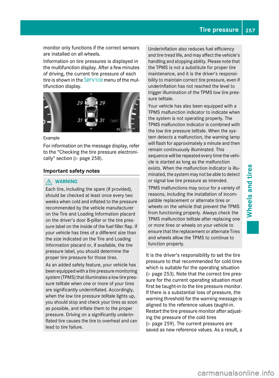
the multifunction display.A fterafew minutes
of driving, the current tire pressure of each
tire is show nintheService Service menu of the mul-
tifunction display. Example
For informatio nonthe message display,r efer
to the "Checking the tire pressure electroni-
cally" section (Y page258).
Important safety notes G
WARNING
Each tire, including the spare (if provided),
should be checked at least once every two
weeks when cold and inflated to the pressure recommended by the vehicl emanufacturer
on the Tire and Loading Information placard
on the driver' sdoor B-pillar or the tire pres-
sure label on the inside of the fuel filler flap .If
yourv ehiclehas tires of adifferent size than
the size indicated on the Tire and Loading
Information placard or, if available, the tire
pressure label, you should determine the
prope rtire pressure for those tires.
As an added safety feature ,you rv ehicl ehas
been equippe dwithatire pressure monitoring
system (TPMS) that illuminates alow tire pres-
sure telltal ewhen one or more of yourt ires
are significantly underinflated. Accordingly,
when the low tire pressure telltal elights up,
you should stop and check yourt ires as soon
as possible, and inflate them to the proper
pressure. Driving on asignificantly underin-
flated tire cause sthe tire to overhea tand can
leadtot ire failure. Underinflation alsor
educes fuel efficiency
and tire tread life ,and may affect the vehicle's
handling and stopping ability .Please note that
the TPMS is not asubstitute for prope rtire
maintenance, and it is the driver' sresponsi-
bility to maintai ncorrect tire pressure, even if
underinflation has not reache dthe level to
trigger illumination of the TPMS low tire pres-
sure telltale.
Yourv ehiclehas alsob een equippe dwith a
TPMS malfunction indicator to indicate when
the system is not operating properly. The
TPMS malfunction indicator is combined with
the low tire pressure telltale. When the sys-
tem detects amalfunction, the warning lamp
willf lashf or approximatel yaminute and then
remai ncontinuously illuminated. This
sequence willber epeated every time the vehi-
cle is started as long as the malfunction
exists. When the malfunction indicator is illu-
minated, the system may not be abletod etect
or signa llow tire pressure as intended.
TPMS malfunctions may occur for avariety of
reasons, including the installation of incom-
patible replacement or alternate tires or
wheels on the vehicl ethat prevent the TPMS
from functioning properly. Always check the
TPMS malfunction telltal eafter replacing one
or more tires or wheels on yourv ehicleto
ensure that the replacement or alternate Tires
and wheels allow the TPMS to continue to
function properly.
It is the driver' sresponsibility to set the tire
pressure to that recommended for cold tires
which is suitable for the operating situation
(Y page2 53).Note that the correct tire pres-
sure for the current operating situation must
first be taught-in to the tire pressure monitor.
If there is asubstantial loss of pressure, the
warning threshol dfor the warning message is
aligned to the reference values taught-in.
Restart the tire pressure monitor after adjust-
ing the pressure of the cold tires
(Y page2 59).The current pressures are
saved as new reference values. As aresult, a Tire pressure
257Wheelsand tires Z