2015 MERCEDES-BENZ GLK-CLASS SUV brake
[x] Cancel search: brakePage 326 of 386
ROnly use jumper cables which have a sufficient cross-section and insulated terminal clamps.
R If the battery is fully discharged, leave the battery tha t is being used to jump-start connected
for a few minutes before attempting to start. This charges the batter y slightly.
R Make sure that the two vehicles do not touch.
Make sure that:
R the jumper cables are not damaged.
R bare parts of the terminal clamp do not come into con tact with other metal parts while the
jumper cables are connected to the battery.
R the jumper cables cannot come into contact with parts su ch as the V-belt pulley or the fan.
These parts move when the engine is started and while it is running.
X Apply the parking brake firmly.
X Shift the automatic transmission to position P.
X Switch off all electrical consumers, e.g. rear window defroster , lighting, etc.
X Open the hood.
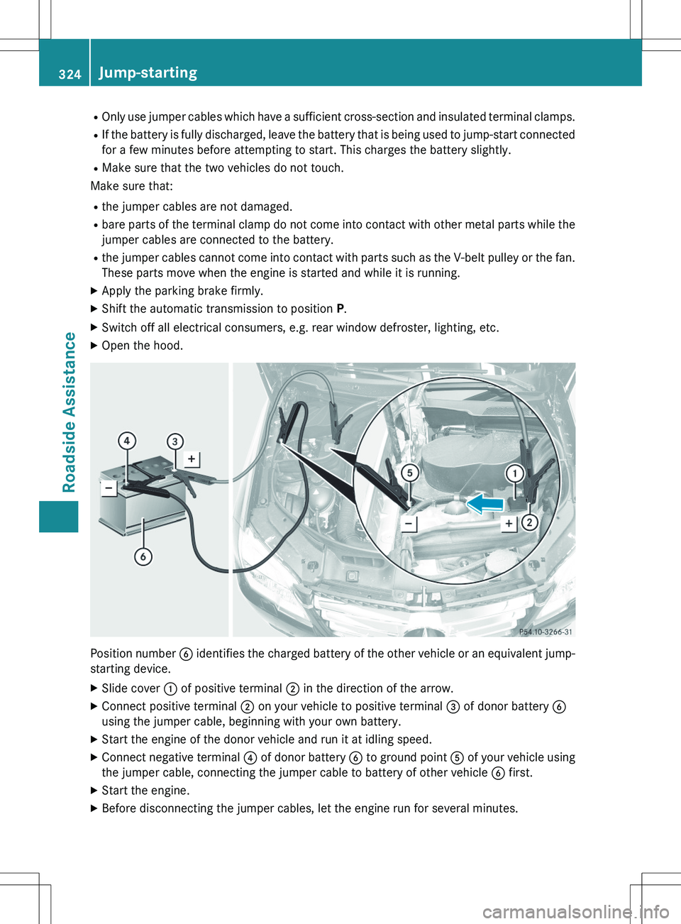
Position number B identifies the charged battery of the other vehicle or a n equivalent jump-
starting device.
X Slide cover : of positive terminal ; in the direction of the arrow.
X Connect positive terminal ; on your vehicle to positive terminal = of donor battery B
using the jumper cable, beginning with your own battery.
X Start the engine of the donor vehicle and run it at idling speed.
X Connect negative terminal ? of donor battery B to ground point A of your vehicle using
the jumper cable, connecting the jumper cable to battery of othe r vehicle B first.
X Start the engine.
X Before disconnecting the jumper cables, let the engine run for sev eral minutes.
324Jump-starting
Roadside Assistance
Page 327 of 386
XFirst, remove the jumper cables from ground point A and negative terminal ?, then from
positive clamp ; and positive terminal =. Begin each time at the contacts on your own
vehicle first.
X Close cover : of positive terminal ; after removing the jumper cables.
X Have the battery checked at a qualified specialist workshop.
iJump-starting is not considered to be a normal operating condit ion.
iJumper cables and further information regarding jump-starting can be obtained at any
qualified specialist workshop.
Towing and tow-starting
Important safety notes
GWARNING
You can no longer steer the vehicle if the
steering wheel lock has been engaged. There is a risk of an accident.
Always switch off the ignition when towing the
vehicle with a tow cable or a tow bar.
GWARNING
When towing or tow-starting another vehicle
and its weight is greater than the permissible gross weight of your vehicle, the:
R the towing eye could detach itself
R the vehicle/trailer combination could roll-
over.
There is a risk of an accident.
When towing or tow-starting another vehicle,
its weight should not be greater than the per- missible gross weight of your vehicle.
Details on the permissible gross vehicle
weight of your vehicle can be found on the
vehicle identification plate ( Y page 372).
! If DISTRONIC PLUS or the HOLD function
is activated, the vehicle brakes automati-
cally in certain situations. To prevent damage to the vehicle, deacti-
vate DISTRONIC PLUS and the HOLD func-
tion in the following or other similar situa-
tions:
R when towing the vehicle
R in the car wash
! The vehicle can be towed a maximum of
30 miles (50km). The towing speed of
30 mph (50 km/h) must not be exceeded.
If the vehicle has to be towed more than
30 miles (50km), the entire vehicle must be
raised and transported.
! Only secure the tow rope or tow bar at the
towing eyes. Otherwise, the vehicle could
be damaged.
! Do not use the towing eyes for recovery
purposes as this could damage the vehicle.
If in doubt, recover the vehicle with a crane.
! When towing, pull away slowly and
smoothly. If the tractive power is too high,
the vehicles could be damaged.
! Do not tow with sling-type equipment.
This could damage the vehicle.
! On vehicles with KEYLESS-GO, use the
SmartKey instead of the Start/Stop but-
ton. Turn the SmartKey to position 2 in the
ignition lock and shift the automatic trans- mission to N. Then, turn the SmartKey back
to 0 and leave it in the ignition lock.
It is better to have the vehicle transported
than to have it towed away.
Towing and tow-starting325
Roadside Assistance
Z
Page 329 of 386
Towing a vehicle with both axles on
the ground
It is important that you observe the safety
instructions when towing away your vehicle
(Y page 325).
X Switch on the hazard warning lamps
(Y page 119).
iWhen towing with the hazard warning
lamps switched on, use the combination
switch as usual to signal a change of direc- tion. In this case, only the indicator lamps
for the direction of travel flash. After reset- ting the combination switch, the hazard
warning lamp starts flashing again.
X Turn the SmartKey to position 2 in the igni-
tion lock.
X When the vehicle is stationary, depress the
brake pedal and keep it depressed.
X Shift the automatic transmission to posi-
tion N.
X Release the brake pedal.
X Release the parking brake.
Towing the vehicle with the rear axle
raised
Only possible for vehicles without
4MATIC.
When towing your vehicle with the rear axle
raised, it is important that you observe the
safety instructions ( Y page 325).
! The ignition must be switched off if you
are towing the vehicle with the rear axle
raised. Intervention by ESP ®
could other-
wise damage the brake system.
X Bring the front wheels into the straight-
ahead position.
X Switch on the hazard warning lamps
(Y page 119). X
Turn the SmartKey to position 0 in the igni-
tion lock and remove the SmartKey from
the ignition lock.
X When leaving the vehicle, take the Smart-
Key or the KEYLESS-GO key with you.
Transporting the vehicle
The towing eyes or trailer tow hitch can be
used to pull the vehicle onto a trailer or trans-
porter if you wish to transport it.
X Turn the SmartKey to position 2 in the igni-
tion lock.
X Shift the automatic transmission to posi-
tion N.
As soon as the vehicle has been loaded:
X Prevent the vehicle from rolling away by
applying the parking brake.
X Shift the automatic transmission to posi-
tion P.
X Turn the SmartKey to position 0 in the igni-
tion lock and remove the SmartKey from
the ignition lock.
X Secure the vehicle.
! You may only secure the vehicle by the
wheels, not by parts of the vehicle such as
axle or steering components. Otherwise,
the vehicle could be damaged.
Notes on 4MATIC vehicles
!
Vehicles with 4MATIC must not be towed
with either the front or the rear axle raised, as doing so will damage the transmission.
If the vehicle has transmission damage or
damage to the front or rear axle, have it trans-
ported on a transporter or trailer.
In the event of damage to the electrical
system
If the battery is defective, the automatic
transmission will be locked in position P. To
shift the automatic transmission to position
N , you must provide power to the vehicle's
Towing and tow-starting327
Roadside Assistance
Z
Page 334 of 386
Useful information
iThis Operator's Manual describes all
models and all standard and optional equip- ment of your vehicle available at the time of
publication of the Operator's Manual.
Country-specific differences are possible.
Please note that your vehicle may not be
equipped with all features described. This
also applies to safety-related systems and
functions.
iRead the information on qualified special-
ist workshops ( Y page 27).
Important safety notes
GWARNING
If wheels and tires of the wrong size are used,
the wheel brakes or suspension components
may be damaged. There is a risk of an acci-
dent.
Always replace wheels and tires with those
that fulfill the specifications of the original
part.
When replacing wheels, make sure to use the
correct:
R designation
R model
When replacing tires, make sure to use the
correct:
R designation
R manufacturer
R model
GWARNING
A flat tire severely impairs the driving, steer-
ing and braking characteristics of the vehicle.
There is a risk of accident.
Tires without run-flat characteristics:
R do not drive with a flat tire.
R immediately replace the flat tire with your
emergency spare wheel or spare wheel, or
consult a qualified specialist workshop.
Tires with run-flat characteristics:
R pay attention to the information and warn-
ing notices on MOExtended tires (tires with
run-flat characteristics).
Accessories that are not approved for your
vehicle by Mercedes-Benz or are not being
used correctly can impair the operating
safety.
Before purchasing and using non-approved
accessories, visit a qualified specialist work-
shop and inquire about: R suitability
R legal stipulations
R factory recommendations
Information on the sizes and types of wheels
and tires for your vehicle can be found in the "Wheel/tire combination" section
( Y page 360).
Information on tire pressure can be found:
R on the vehicle's Tire and Loading Informa-
tion placard on the B-pillar ( Y page 343)
R on the tire pressure label on the fuel filler
flap ( Y page 164)
R under "Tire pressure" ( Y page 336)
Operation
Information on driving
R
Check the tire pressure when the vehicle is
heavily laden and adjust prior to a trip.
R While driving, pay attention to vibrations,
noises and unusual handling characteris-
tics, e.g. pulling to one side. This may indi-
cate that the wheels or tires are damaged.
If you suspect that a tire is defective,
reduce your speed immediately. Stop the
vehicle as soon as possible to check the
wheels and tires for damage. Hidden tire
damage could also be causing the unusual
handling characteristics. If you find no
332Operation
Wheels and tires
Page 345 of 386
Radio type approval for the tire pres-
sure monitor
CountryRadio type approval number
USAFCC ID: MRXMW2433A
FCC ID: MRXGG4
FCC ID: MRXMC34MA4
CanadaIC: 2546A-MW2433A
IC: 2546A-GG4
IC: 2546A-MC34MA4
Loading the vehicle
Instruction labels for tires and loads
GWARNING
Overloaded tires can overheat, causing a
blowout. Overloaded tires can also impair thesteering and driving characteristics and lead
to brake failure. There is a risk of accident.
Observe the load rating of the tires. The load
rating must be at least half of the GAWR of
your vehicle. Never overload the tires by
exceeding the maximum load.
Two instruction labels on your vehicle show
the maximum possible load.
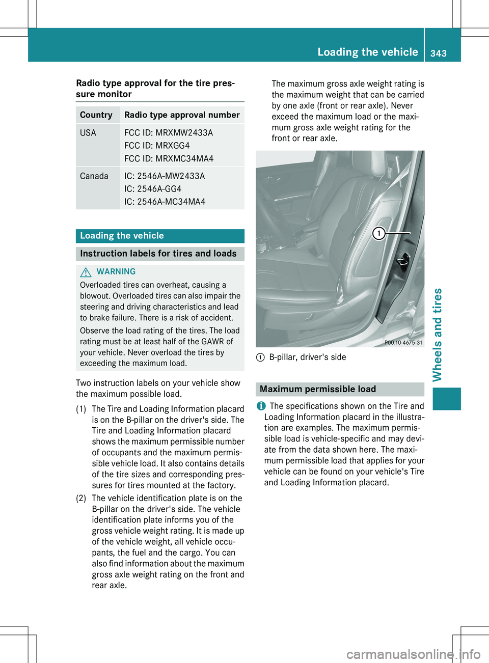
(1) The Tire and Loading Information placard is on the B-pillar on the driver's side. The
Tire and Loading Information placard
shows the maximum permissible number
of occupants and the maximum permis-
sible vehicle load. It also contains details
of the tire sizes and corresponding pres-
sures for tires mounted at the factory.
(2) The vehicle identification plate is on the B-pillar on the driver's side. The vehicle
identification plate informs you of the
gross vehicle weight rating. It is made up
of the vehicle weight, all vehicle occu-
pants, the fuel and the cargo. You can
also find information about the maximum gross axle weight rating on the front and
rear axle. The maximum gross axle weight rating is
the maximum weight that can be carried
by one axle (front or rear axle). Never
exceed the maximum load or the maxi-
mum gross axle weight rating for the
front or rear axle.
:B-pillar, driver's side
Maximum permissible load
iThe specifications shown on the Tire and
Loading Information placard in the illustra-
tion are examples. The maximum permis-
sible load is vehicle-specific and may devi-
ate from the data shown here. The maxi-
mum permissible load that applies for your vehicle can be found on your vehicle's Tire
and Loading Information placard.
Loading the vehicle343
Wheels and tires
Z
Page 356 of 386
Maximum load on one tire
Maximum load on one tire. This is calculated
by dividing the maximum axle load of one axleby two.
PSI (pounds per square inch)
A standard unit of measure for tire pressure.
Aspect ratio
Relationship between tire height and tire
width in percent.
Tire pressure
This is pressure inside the tire applying an
outward force to each square inch of the tire's surface. The tire pressure is specified in
pounds per square inch (psi), in kilopascal
(kPa) or in bar. The tire pressure should only
be corrected when the tires are cold.
Tire pressure of cold tires
The tires are cold:
R if the vehicle has been parked without
direct sunlight on the tires for at least three
hours and
R if the vehicle has not been driven further
than 1 mile (1.6 km)
Tread
The part of the tire that comes into contact
with the road.
Bead
The tire bead ensures that the tire sits
securely on the wheel. There are several steel
wires in the bead to prevent the tire from
coming loose from the wheel rim.
Sidewall
The part of the tire between the tread and the
bead.
Weight of optional extras
The combined weight of those optional extras that weigh more than the replaced standard
parts and more than 2.3 kg (5 lbs). These
optional extras, such as high-performance
brakes, level control, a roof rack or a high-
performance battery, are not included in the
curb weight and the weight of the accesso-
ries.
TIN (Tire Identification Number)
This is a unique identifier which can be used
by a tire manufacturer to identify tires, for
example for a product recall, and thus identifythe purchasers. The TIN is made up of the
manufacturer's identity code, tire size, tire
type code and the manufacturing date.
Load bearing index
The load bearing index (also load index) is a
code that contains the maximum load bearing
capacity of a tire.
Traction
Traction is the result of friction between the
tires and the road surface.
TWR (Tongue Weight Rating)
The TWR specifies the maximum permissible
weight that the ball coupling of the trailer tow
hitch can support.
354Definition of terms for tires and loading
Wheels and tires
Page 357 of 386
Treadwear indicators
Narrow bars (tread wear bars) that are dis-
tributed over the tire tread. If the tire tread islevel with the bars, the wear limit of á in
(1.6 mm) has been reached.
Occupant distribution
The distribution of occupants in a vehicle at
their designated seating positions.
Total load limit
Nominal load and luggage load plus 68 kg
(150 lbs) multiplied by the number of seats in the vehicle.
Changing a wheel
Flat tire
You can find information on what to do in theevent of a flat tire in the "Flat tire" section
( Y page 314).
Information on driving with MOExtended tires
in the event of a flat tire can be found under
"MOExtended tires (tires with run-flat char-
acteristics" ( Y page 315).
Rotating the wheels
GWARNING
Interchanging the front and rear wheels may
severely impair the driving characteristics if
the wheels or tires have different dimensions.
The wheel brakes or suspension components
may also be damaged. There is a risk of acci-
dent.
Rotate front and rear wheels only if the wheels and tires are of the same dimensions.
! On vehicles equipped with a tire pressure
monitor, electronic components are loca-
ted in the wheel. Tire-mounting tools should not be used
near the valve. This could damage the elec-
tronic components.
Only have tires changed at a qualified spe-cialist workshop.
Always observe the instructions and safety
notes in the "Mounting a wheel" section
( Y page 356).
The wear patterns on the front and rear tires
differ, depending on the operating conditions.
Rotate the wheels before a clear wear pattern has formed on the tires. Front tires typically
wear more on the shoulders and the rear tires in the center.
If your vehicle's tire configuration allows, you can rotate the wheels according to the inter-
vals in the tire manufacturer's warranty book
in your vehicle documents. If no warranty
book is available, the tires should be rotated
every 3,000 to 6,000 miles (5,000 to
10,000 km), or earlier if tire wear requires. Do
not change the direction of wheel rotation.
Clean the contact surfaces of the wheel and
the brake disc thoroughly every time a wheel
is rotated. Check the tire pressure and reac-
tivate the tire pressure monitor if necessary.
Information on changing tires and mounting
the spare wheel ( Y page 355).
Direction of rotation
Tires with a specified direction of rotation
have additional benefits, e.g. if there is a risk
of hydroplaning. These advantages can only
be gained if the tires are installed correspond- ing to the direction of rotation.
An arrow on the sidewall of the tire indicates
its correct direction of rotation.
Storing wheels
Store wheels that are not being used in a cool,
dry and preferably dark place. Protect the
tires from oil, grease, gasoline and diesel.
Changing a wheel355
Wheels and tires
Z
Page 358 of 386
Mounting a wheel
Preparing the vehicle
XStop the vehicle on solid, non-slippery and
level ground.
X Apply the parking brake.
X Bring the front wheels into the straight-
ahead position.
X Move the selector lever to position P.
X Switch off the engine.
X Vehicles without KEYLESS-GO: remove
the SmartKey from the ignition lock.
X Vehicles with KEYLESS-GO: open the
driver's door.
The on-board electronics have status 0,
which is the same as the SmartKey having
been removed.
X Vehicles with KEYLESS-GO: remove the
Start/Stop button from the ignition lock
( Y page 149).
X If a trailer is coupled to the vehicle, uncou-
ple it.
X If included in the vehicle equipment,
remove the tire-change tool kit from the
vehicle.
X In addition, safeguard the vehicle against
rolling away.
Securing the vehicle to prevent it
from rolling away
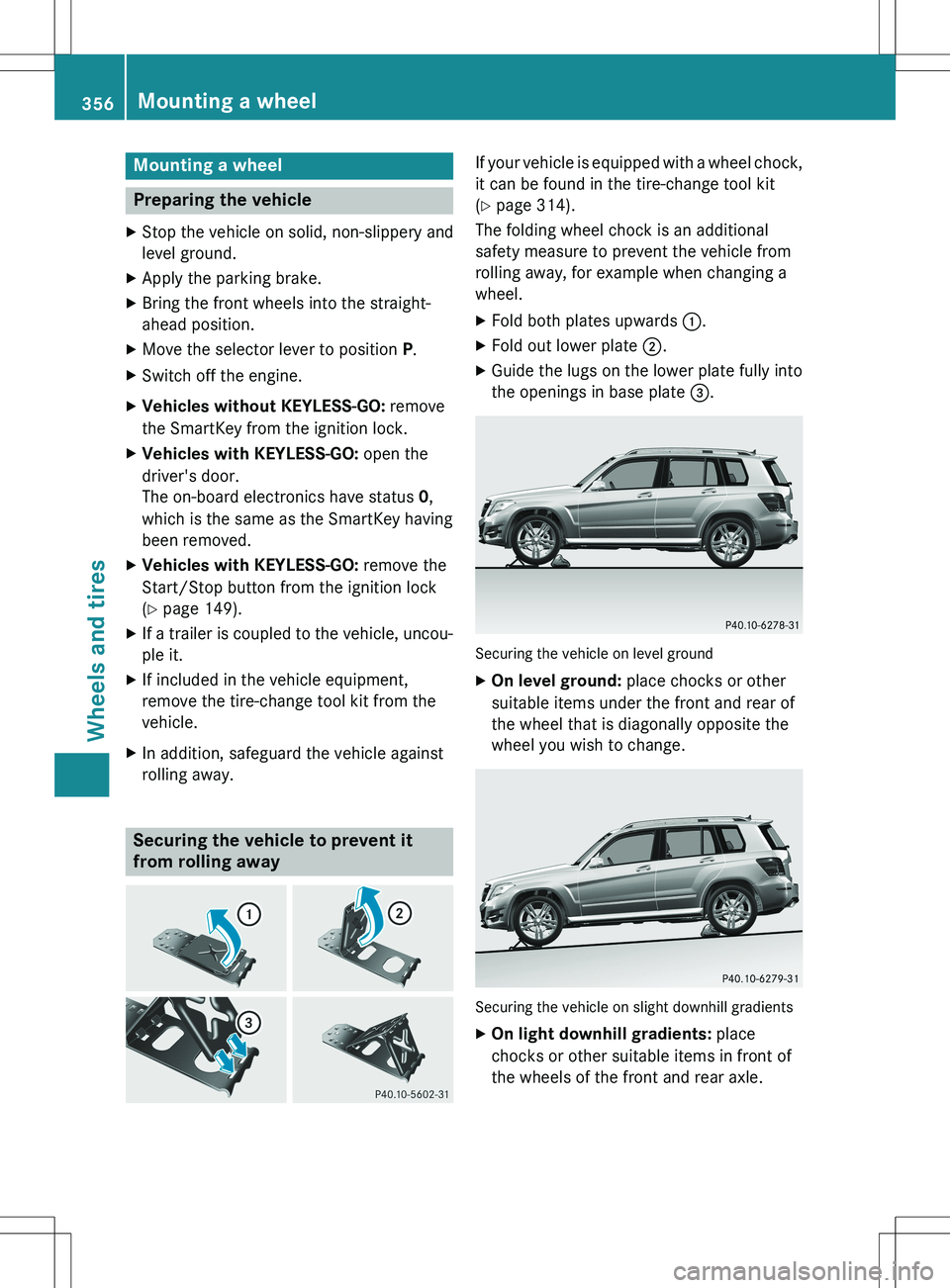
If your vehicle is equipped with a wheel chock,
it can be found in the tire-change tool kit
( Y page 314).
The folding wheel chock is an additional
safety measure to prevent the vehicle from
rolling away, for example when changing a
wheel.
X Fold both plates upwards :.
X Fold out lower plate ;.
X Guide the lugs on the lower plate fully into
the openings in base plate =.
Securing the vehicle on level ground
X
On level ground: place chocks or other
suitable items under the front and rear of
the wheel that is diagonally opposite the
wheel you wish to change.
Securing the vehicle on slight downhill gradients
X On light downhill gradients: place
chocks or other suitable items in front of
the wheels of the front and rear axle.
356Mounting a wheel
Wheels and tires