2015 MERCEDES-BENZ GLE SUV fuse box
[x] Cancel search: fuse boxPage 14 of 453
ETS/4ETS (Electronic Traction Sys-
tem) ...................................................... 76
Exhaust pipe (cleaning instruc-
tions) .................................................. 383
Exhaustive discharging (high-volt-
age battery) ...................................... .394
Exterior mirrors
Adjusting ....................................... 117
Anti-dazzle mode (automatic) ....... .118
Folding in when locking (on-board
computer) ...................................... 296
Folding in/out (automatically) ....... 118
Folding in/out (electrically) ........... 118
Out of position (troubleshooting) ... 118
Parking position ............................. 119
Resetting ....................................... 118
Storing settings (memory func-
tion) ............................................... 120 F
Fault message see Display messages
Filler cap
see Fuel filler flap
Fire extinguisher ............................... 387
First-aid kit ......................................... 386
Fitting a wheel
Fitting a wheel ............................... 416
Lowering the vehicle ...................... 417
Preparing the vehicle ..................... 414
Raising the vehicle ......................... 415
Removing a whee l.......................... 416
Securing the vehicle against roll-
ing away ........................................ 414
Flat tyre
MOExtended tyre s......................... 388
Preparing the vehicle ..................... 388
TIREFIT kit ...................................... 389
see Emergency spare wheel
Floormat ............................................. 372
Foglamps (extended range) .............. 125
Folding the rear bench seat for-
wards/back ....................................... 354
Fording
Off-road ......................................... 198
On flooded roads ........................... 197 Frequencies
Garage door opener ....................... 369
Mobile phone ................................. 433
Two-way radio ................................ 433
Front-passenger front airbag deac-
tivation
Display message ............................ 311
Front-passenger front airbag deac-
tivation system
Operation ......................................... 51
Problems ......................................... 55
System self-test ............................... 54
Fuel
Additives ........................................ 437
Consumption information .............. 438
Consumption statistics .................. 284
Displaying the current consump-
tion ................................................ 285
Displaying the range ...................... 285
Driving tips .................................... 194
Fuel gaug e....................................... 32
Grade (petrol) ................................ 436
Important safety notes .................. 436
Low outside temperatures ............. 438
Notes for Mercedes‑ AMG vehi-
cles ................................................ 437
Problem (malfunction) ................... 179
Quality (diesel )............................... 438
Refuelling ....................................... 175
Tank content/reserve fue l............. 436
Fuel filler flap
Opening ......................................... 177
Opening (PLUG-IN HYBRID vehi-
cles) ............................................... 177
Fuel filter (white display message) .. 318
Fuel level
Calling up the range (on-board
computer) ...................................... 285
Gaug e.............................................. 32
Fuel tank
Capacity ........................................ 436
Problem (malfunction) ................... 179
Fuses
Allocation chart ............................. 402
Before changing ............................. 402
Dashboard fuse box ....................... 402
Fuse box in the engine compart-
ment .............................................. 403 Index
11
Page 15 of 453
Fuse box under rear bench sea
t.... 403
Important safety notes .................. 402 G
Garage door opener Clearing the memory ..................... 369
Frequencies ................................... 369
General notes ................................ 367
Important safety notes .................. 367
Opening/closing the garage doo r..3 68
Programming (button in the rear-
view mirror) ................................... 367
Synchronising the rolling code ....... 368
Gear indicator (on-board com-
puter, Mercedes-AMG vehicles) ....... 297
Gearshift paddles
see Steering wheel gearshift paddles
Gearshift program
SETUP (on-board computer) .......... 298
Genuine Mercedes-Benz parts ........... 25
Glove compartment .......................... 352H
Hazard warning lamps ......................124
Head restraints
Adjusting ....................................... 109
Adjusting (electrically) ................... 110
Adjusting (manually) ..................... .110
Adjusting (rear) .............................. 110
Fitting/removing (rear) .................. 111
Luxury ............................................ 110
Headlamp
Cleaning system (notes) ................ 442
Headlamps
Misting up ...................................... 127
see Automatic headlamp mode
Heating
see Climate control
High-pressure cleaners .................... 380
High-voltage battery
Battery care ................................... 184
Charging ........................................ 396
Charging (charging station) ............ 189
Charging (mains socket) ................ 185
Charging (wallbox) ......................... 188
Charging cable heating up ............. 185 Energy consumption .....................
.184
General notes .................................. 42
Method of operation ..................... .183
Outside temperatures .................... 184
Problems during charging .............. 190
Protective device ........................... 185
Range ............................................ 184
Terms of use .................................. 184
Vehicle fire ....................................... 42
Hill start assist .................................. 161
HOLD function
Deactivating ................................... 220
Display message ............................ 325
Function/notes ............................ .219
Horn ...................................................... 30
Hybrid drive system
Automatic switch off ........................ 41
Danger of electric shock .................. 41
Display message ............................ 320
General notes .................................. 41
High-voltage battery ........................ 42
Important safety notes .................... 41
Manual switch off ............................ 41
Opening the bonnet ......................... 42
Warning lamp ................................. 340
Hybrid vehicles
Important safety notes .................... 41 I
Ignition lock see Key positions
Immobiliser .......................................... 81
Indicator and warning lamp
Restraint system ............................ 346
Indicator and warning lamps
Coolant .......................................... 347
DISTRONIC PLUS ........................... 349
Engine diagnostics ......................... 347
Indicator lamps
Display message ............................ 313
see Warning and indicator lamps
Indicators
see Turn signals
Insect protection on the radiator .... 374
Instrument cluster
Overview .......................................... 32
Warning and indicator lamps ........... 34 12
Index
Page 188 of 453
Heat generated by the charging cable
and charging cable connector Observe the "Important safety notes"
(Y
page 182).
During the charging process, the charging cable
and charging cable connector may heat up.
The charging cable and the charging cable con- nector will only heat up within the permissible
limiting values, provided that:
R the mains power supply and the charging
cable are not damaged
R the instructions for handling the charging
cable and controls on the charging cable are
observed
If the charging cable or charging cable connec-
tor become too hot, have the mains power sup- ply checked.
Protection against overvoltage !
Voltage surges in the mains supply can dam-
age the vehicle. The vehicle is therefore
equipped with a device which protects it from
voltage surges in the mains supply. This
device may be triggered during severe thun-
derstorms, for example, and may lead to the
building's fuse being tripped and an interrup-
tion in the power supply. These functions pro-
tect the vehicle. After the building fuse is
switched on again, the charging process
resumes automatically. Following an interrup-
tion in the power supply or tripping of the
building's fuse, it may take up to 10 minutes
for charging to resume automatically.
Reset the building's circuit breaker. Otherwise,
the charging process cannot be continued.
General information on the charging
process Observe the "Important safety notes"
(Y page 182).
The vehicle socket is located in the rear bumper on the right below the tail lamp.
The charge socket flap and the vehicle are cen-
trally locked or unlocked simultaneously. Charging the high-voltage battery via
the mains socket
Charging cable for mains sockets Important safety notes
! Only use the charging cable to charge the
high-voltage battery. Do not use the charging cable for other purposes. It may otherwise be damaged.
The vehicle is supplied with a country-specific
charging cable, variant 1 or variant 2, for con-
nection to a mains socket. The controls of the
two charging cable variants are different. Only
use the charging cable supplied with the vehicle
or a charging cable approved for the vehicle.
i The charging process can vary depending on
the mains power supply. Therefore, always
observe the local information.
i For short charge times (charging with 16
A),
connect the fast-charging cable to a wallbox
or charging station without a preinstalled
cable. You can also use the optionally availa-
ble charging cable with the CE plug.
Information about charging from a wallbox
(Y page 188).
Information about charging from a charging sta-
tion (Y page 189).
Stowing the charging cable The charging cable can be stowed and secured
in the bag provided in the luggage compartment
of the vehicle.
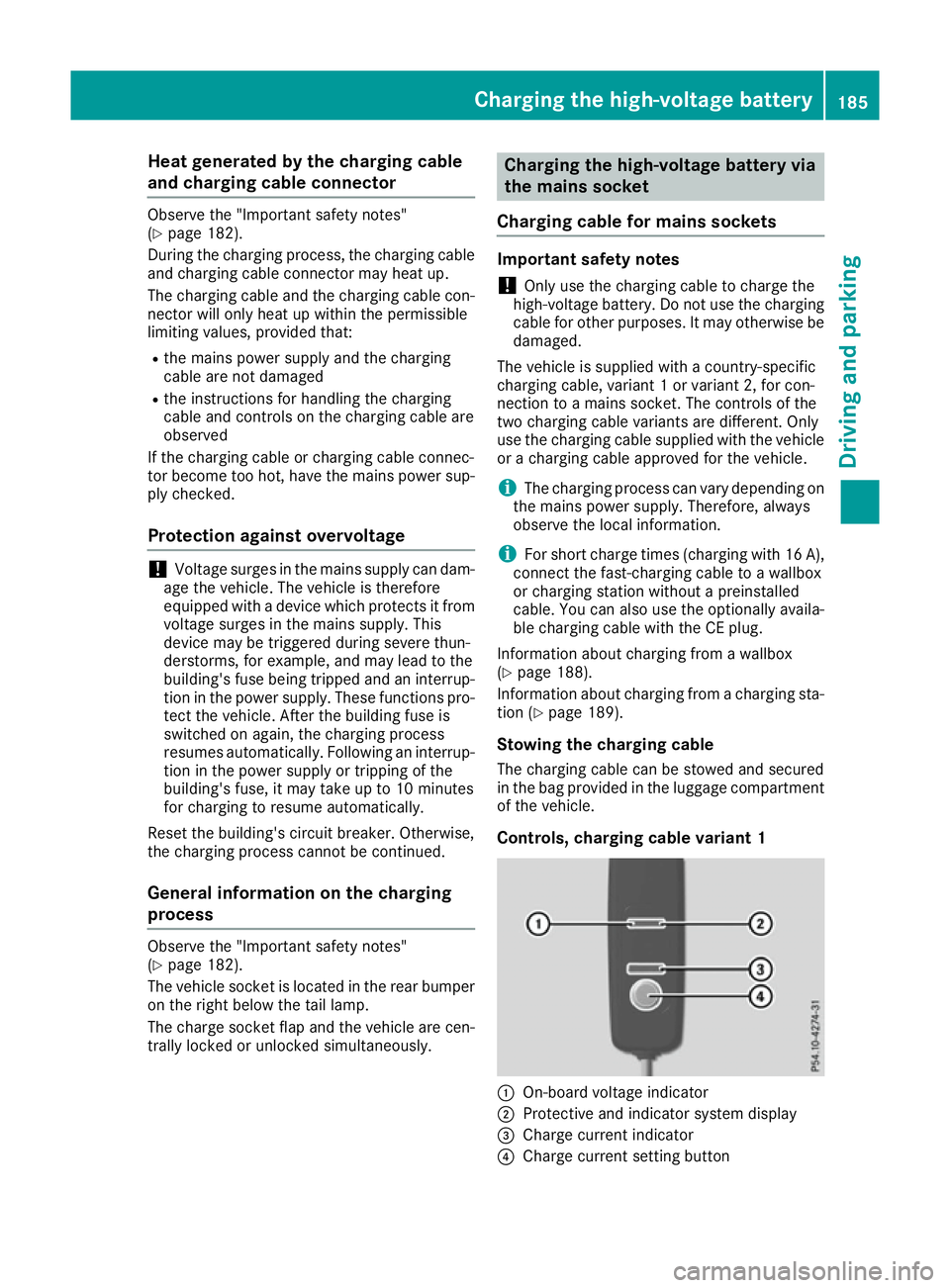
Controls, charging cable variant 1 :
On-board voltage indicator
; Protective and indicator system display
= Charge current indicator
? Charge current setting button Charging the high-voltage battery
185Driving and parking Z
Page 405 of 453
Information for 4MATIC vehicles
! Vehicles with 4MATIC must not be towed
with the front or rear axle raised; otherwise,
the transmission may be damaged.
Vehicles with 4MATIC may either be towed away
with both axles on the ground or be loaded up
and transported.
If the vehicle has transmission damage or dam- age to the front or rear axle, have it transportedon a transporter or trailer.
In the event of damage to the electrical sys-
tem: if the battery is defective, the automatic
transmission will be locked in position P. To shift
the automatic transmission to position N, you
must provide power to the vehicle's on-board
electrical system in the same way as when jump- starting (Y page 397).
Have the vehicle transported on a transporter or trailer. Tow-starting (emergency engine
starting)
! Do not tow-start vehicles with automatic
transmission. You could otherwise damage
the automatic transmission.
You can find information on "Jump-starting"
under (Y page 397). Electrical fuses
Important safety notes
G
WARNING
If you manipulate, bridge or replace a faulty
fuse with a fuse of a higher amperage, the
electric cables could be overloaded. This may result in a fire. There is a risk of an accident
and injury.
Always replace faulty fuses with specified new fuses of the correct amperage.
! Only use fuses marked with an "S" for the
fuse box in the engine compartment and
under the rear bench seat. Components or
systems could otherwise be damaged. The fuses in your vehicle disconnect faulty cir-
cuits. If a fuse blows, all the components on the
circuit and their functions will fail.
Blown fuses must be replaced with fuses of the same rating, which you can recognise by the
colour and fuse rating. The fuse ratings are listed
in the fuse allocation chart.
The fuse allocation chart is located in the fuse
box under the rear bench seat (Y page 403).
If the newly inserted fuse also blows, have the
cause traced and rectified at a qualified special-
ist workshop, e.g. a Mercedes-Benz Service
Centre. Before replacing a fuse
Observe the important safety notes
(Y page 402)
X Secure the vehicle against rolling away
(Y page 191).
X Switch off the engine.
X Switch off all electrical consumers.
X Remove the key from the ignition lock.
or, on vehicles with KEYLESS-GO start function
or KEYLESS‑GO: X Open the driver's door.
The on-board electronics now have status 0.
This is the same as the key having been
removed.
The driver's door can be closed again.
All indicator lamps in the instrument cluster
must be off.
The fuses are located in various fuse boxes: R Fuse box on the front-passenger side of the
dashboard
R Fuse box in the engine compartment on the
right-hand side of the vehicle, when viewed in
the direction of travel
R Fuse box under the rear bench seat Dashboard fuse box
Observe the important safety notes
(Y page 402).
! Do not use a pointed object such as a screw-
driver to open the cover in the dashboard. You
could damage the dashboard or the cover. 402
Electrical fusesBreakdown assistance
Page 406 of 453
!
Make sure that no moisture can enter the
fuse box when the cover is open.
! When closing the cover, make sure that it is
lying correctly on the fuse box. Moisture seep-
ing in or dirt could otherwise impair the oper- ation of the fuses. X
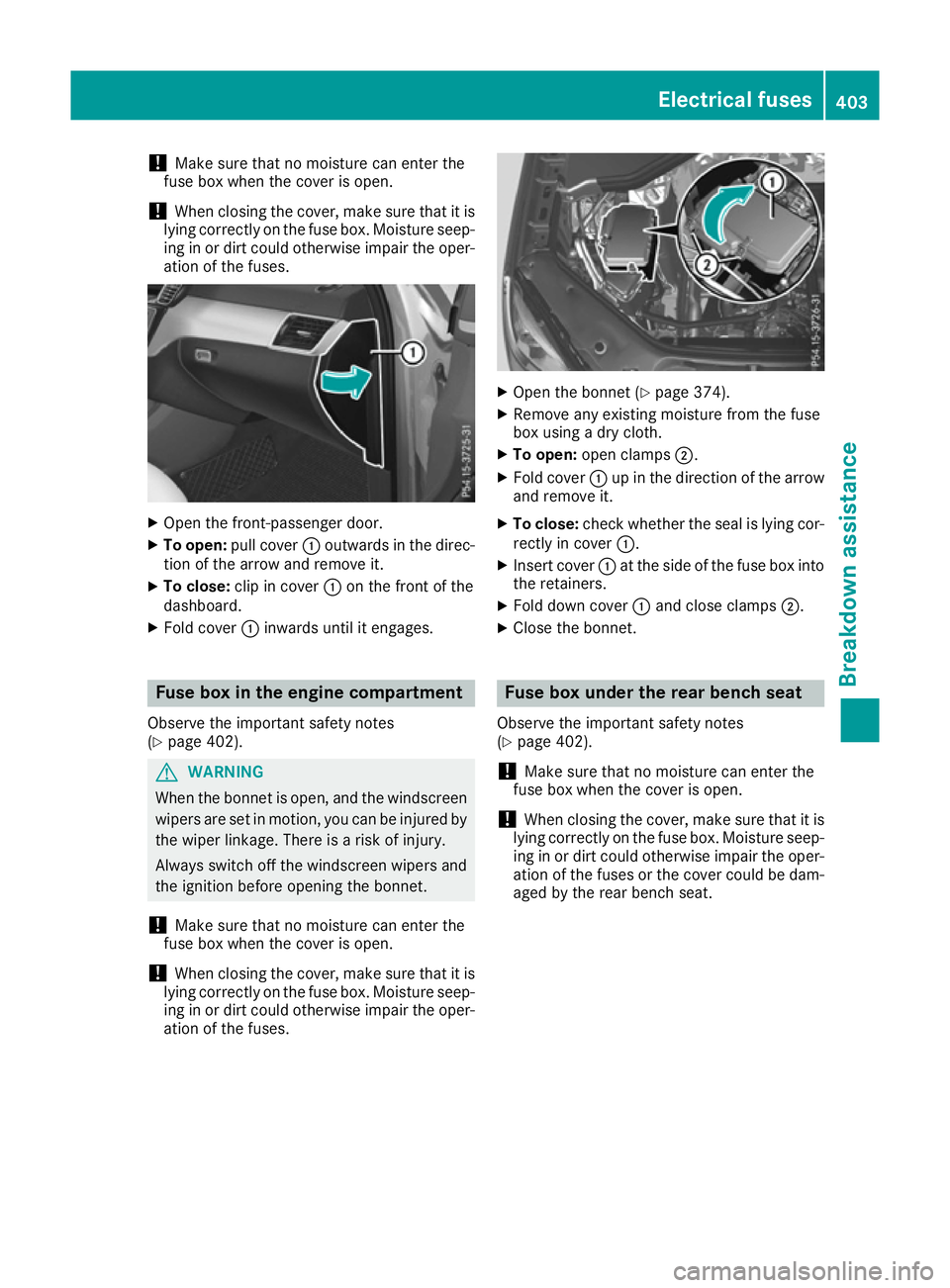
Open the front-passenger door.
X To open: pull cover :outwards in the direc-
tion of the arrow and remove it.
X To close: clip in cover :on the front of the
dashboard.
X Fold cover :inwards until it engages. Fuse box in the engine compartment
Observe the important safety notes
(Y page 402). G
WARNING
When the bonnet is open, and the windscreen wipers are set in motion, you can be injured by
the wiper linkage. There is a risk of injury.
Always switch off the windscreen wipers and
the ignition before opening the bonnet.
! Make sure that no moisture can enter the
fuse box when the cover is open.
! When closing the cover, make sure that it is
lying correctly on the fuse box. Moisture seep-
ing in or dirt could otherwise impair the oper- ation of the fuses. X
Open the bonnet (Y page 374).
X Remove any existing moisture from the fuse
box using a dry cloth.
X To open: open clamps ;.
X Fold cover :up in the direction of the arrow
and remove it.
X To close: check whether the seal is lying cor-
rectly in cover :.
X Insert cover :at the side of the fuse box into
the retainers.
X Fold down cover :and close clamps ;.
X Close the bonnet. Fuse box under the rear bench seat
Observe the important safety notes
(Y page 402).
! Make sure that no moisture can enter the
fuse box when the cover is open.
! When closing the cover, make sure that it is
lying correctly on the fuse box. Moisture seep-
ing in or dirt could otherwise impair the oper- ation of the fuses or the cover could be dam-aged by the rear bench seat. Electrical fuses
403Breakdown assistance Z
Page 407 of 453
X
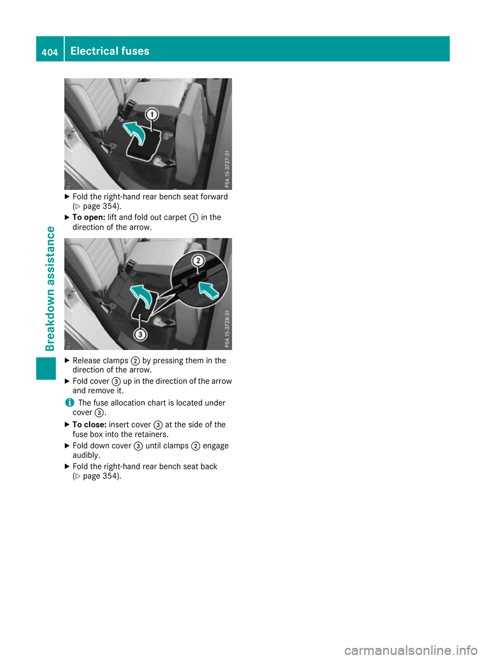
Fold the right-hand rear bench seat forward
(Y page 354).
X To open: lift and fold out carpet :in the
direction of the arrow. X
Release clamps ;by pressing them in the
direction of the arrow.
X Fold cover =up in the direction of the arrow
and remove it.
i The fuse allocation chart is located under
cover =.
X To close: insert cover =at the side of the
fuse box into the retainers.
X Fold down cover =until clamps ;engage
audibly.
X Fold the right-hand rear bench seat back
(Y page 354). 404
Electrical fusesBreakdown assistance