2015 MERCEDES-BENZ GLE SUV service reset
[x] Cancel search: service resetPage 7 of 453
Important safety guidelines .............48
Kneebag ........................................... 50
Sidebag ............................................ 50
Triggering .........................................55
Windowbag ...................................... 51
AIRMATIC package
ADS (Adaptive Damping System )... 221
Function/note s............................. 220
Alarm
ATA (Anti-Theft Alarm system) ......... 81
Switching off (ATA) .......................... 81
Switching the function on/off
(ATA) ................................................ 81
Alarm system
see ATA (Anti-Theft Alarm system)
AMG
RIDE CONTROL sports suspen-
sion ................................................ 224
AMG menu (on-board computer) ..... 297
Anti-glare film .................................... 372
Anti-lock braking system
see ABS (Anti-lock Braking System)
Anti-Theft Alarm system
see ATA (Anti-Theft Alarm system)
Approach/departure angle .............. 202
Aquaplaning ....................................... 197
Ashtray ............................................... 363
Assistance display (on-board com-
puter) .................................................. 290
Assistance menu (on-board com-
puter) .................................................. 289
ASSYST PLUS
Displaying a service message ........ 378
Hiding a service message .............. 378
Resetting the service interval dis-
play ................................................ 378
Service message ............................ 377
Special service requirements ......... 378
ATA (Anti-Theft Alarm system)
Activating/deactivating ................... 81
Function ........................................... 81
Switching off the alarm .................... 81
ATTENTION ASSIST
Activating/deactivating ................. 291
Display message ............................ 322
Function/note s............................. 240
Audio menu (on-board computer) .... 287Authorised workshop
see Qualified specialist workshop
AUTO lights
Display message ............................ 315
see Lights
Automatic engine start (ECO start/
stop function) .................................... 162
Automatic engine switch-off (ECO
start/stop function) .......................... 162
Automatic front-passenger front
airbag deactivation
Display message ............................ 311
Automatic front-passenger front
airbag deactivation system
Operation ......................................... 51
Problems ......................................... 55
System self-test ............................... 54
Automatic headlamp mode .............. 122
Automatic transmission
Accelerator pedal position ............. 170
Changing gear ............................... 170
DIRECT SELECT lever ..................... 168
Display message ............................ 332
Drive program display .................... 168
Drive programs .............................. 171
Driving tips .................................... 170
DYNAMIC SELECT controlle r......... 166
Emergency running mode .............. 175
Engaging drive position .................. 169
Engaging neutral ............................ 169
Engaging park position automati-
cally ............................................... 168
Engaging reverse gear ................... 168
Engaging the park position ............ 168
Gliding mod e................................. 170
Kickdown ....................................... 170
Manual shifting .............................. 172
Oil temperature (on-board com-
puter, Mercedes-AMG vehicles) ..... 297
Overview ........................................ 167
Problem (fault) ............................... 175
Pulling away ................................... 161
Starting the engine ........................ 160
Steering wheel gearshift paddle s... 172
Trailer towing ................................. 171
Transmission position display ........ 168
Transmission positions .................. 170 4
Index
Page 25 of 453
With both axles on the ground .......4
01
Towing eye ......................................... 387
Traffic Sign Assist
Activating/deactivating the warn-ing function ................................... .290
Display message ............................ 325
Function/notes ............................ .242
Important safety notes .................. 242
Instrument cluster display ............. 243
Trailer coupling
see Towing a trailer
Trailer towing
7-pin connector ............................ .278
Blind Spot Assist ............................ 246
Cleaning the trailer tow hitch ......... 383
Coupling up a trailer ..................... .275
Decoupling a trailer ....................... 276
Driving tips ................................... .273
Important safety notes .................. 272
Lights display message .................. 313
Mounting dimensions .................... 446
Parktronic ...................................... 225
Power supply ................................. 277
Problem (fault) ............................... 279
Trailer loads ................................... 447
Transmission
see Automatic transmission
Transmission position display ......... 168
Transmission position display
(DIRECT SELECT lever) ......................168
Transporting the vehicle .................. 401
Travelling uphill
Brow of hill ..................................... 202
Driving downhill ............................ .202
Maximum gradient-climbing capa-
bility ............................................... 202
Trim pieces (cleaning instruc-
tions) ................................................. .384
Trip computer (on-board com-
puter) ................................................. .284
Trip meter
Calling up ....................................... 284
Resetting (on-board computer) ...... 285
Turn signals
Changing bulbs (front) ................... 130
Switching on/off ........................... 123 TV
Operating (on-board computer) ..... 288
see Separate operating instructions
Two-way radio
Frequencies ................................... 433
Installation ..................................... 433
Transmission output (maximum ).... 433
Type identification plate
see Vehicle identification plate
Tyre inflation compressor
see TIREFIT kit
Tyre pressure
Calling up (on-board computer) ..... 411
Display message ............................ 330
Not reached (TIREFIT) .................... 391
Reached (TIREFIT) .......................... 391
Recommended ............................... 408
Tyre pressure loss warning
General notes ................................ 410
Important safety notes .................. 410
Restarting ...................................... 410
Tyre pressure monitor
Checking the tyre pressure elec-
tronically ........................................ 411
Function/note s............................. 411
General notes ................................ 411
Important safety notes .................. 411
Radio type approval for the tyre
pressure monitor ........................... 413
Restarting ...................................... 412
Warning lamp ................................. 350
Warning message .......................... 412
Tyres
Changing a whee l.......................... 413
Checking ........................................ 406
Direction of rotation ...................... 414
Display message ............................ 330
General notes ................................ 418
Important safety notes .................. 405
Information on driving .................... 405
M+S tyres ...................................... 407
MOExtended tyre s......................... 407
Replacing ....................................... 413
Service life ..................................... 406
Storing ........................................... 414
Tyre size (data ).............................. 418
Tyre tread ...................................... 406
Wheel and tyre combinations ........ 419 22
Index
Page 30 of 453
Always have work on electrical and electronic
components carried out at a qualified special-ist workshop.
If you make any changes to the vehicle elec-
tronics, the general operating permit is ren-
dered invalid.
! There is a risk of damage to the vehicle if:
R the vehicle becomes stuck, e.g. on a high
kerb or an unpaved road
R you drive too fast over an obstacle, e.g. a
kerb or a pothole in the road
R a heavy object strikes the underbody or
parts of the chassis
In situations like this, the body, the under-
body, chassis parts, wheels or tyres could be
damaged without the damage being visible.
Components damaged in this way can unex-
pectedly fail or, in the case of an accident, no
longer withstand the strain they are designed for.
If the underbody panelling is damaged, com-
bustible materials such as leaves, grass or
twigs can gather between the underbody and
the underbody panelling. If these materials
come in contact with hot parts of the exhaust
system, they can catch fire.
In such situations, have the vehicle checked
and repaired immediately at a qualified spe-
cialist workshop. If, upon continuing your
journey, you notice that driving safety is
impaired, pull over and stop the vehicle imme- diately, paying attention to road and traffic
conditions. In such cases, consult a qualified
specialist workshop. Declarations of conformity
Wireless vehicle components The following information applies to all compo-
nents of the vehicle and the information sys-
tems and communication devices integrated
into the vehicle which receive and/or transmit
radio waves:
The components of this vehicle that receive
and/or transmit radio waves are compliant with
the basic requirements and all other relevant
conditions of Directive 1999/5/EC. You can
obtain further information from any Mercedes-
Benz Service Centre. Electromagnetic compatibility The electromagnetic compatibility of the vehicle
components has been checked and certified
according to the currently valid version of Reg-
ulation ECE-R 10. Diagnostics connection
The diagnostics connection is only intended for the connection of diagnostic equipment at a
qualified specialist workshop. G
WARNING
If you connect equipment to a diagnostics
connection in the vehicle, it can affect the
operation of the vehicle systems. This may
affect the operating safety of the vehicle.
There is a risk of an accident.
Do not connect any equipment to a diagnos-
tics connection in the vehicle. G
WARNING
Objects in the driver's footwell may restrict
the clearance around the pedals or block a
depressed pedal. This jeopardises the oper-
ating and road safety of the vehicle. There is a risk of an accident.
Stow all objects securely in the vehicle so that
they do not get into the driver's footwell.
Always fit the floormats securely and as pre-
scribed in order to ensure that there is always sufficient room for the pedals. Do not use
loose floormats and do not place several floor-mats on top of one another.
! If the engine is switched off and equipment
on the diagnostics connection is used, the
starter battery may discharge.
Connecting equipment to the diagnostics con-
nection can lead to emissions monitoring infor-
mation being reset, for example. This may lead
to the vehicle failing to meet the requirements of
the next emissions test during the main inspec- tion. Introduction
27 Z
Page 291 of 453
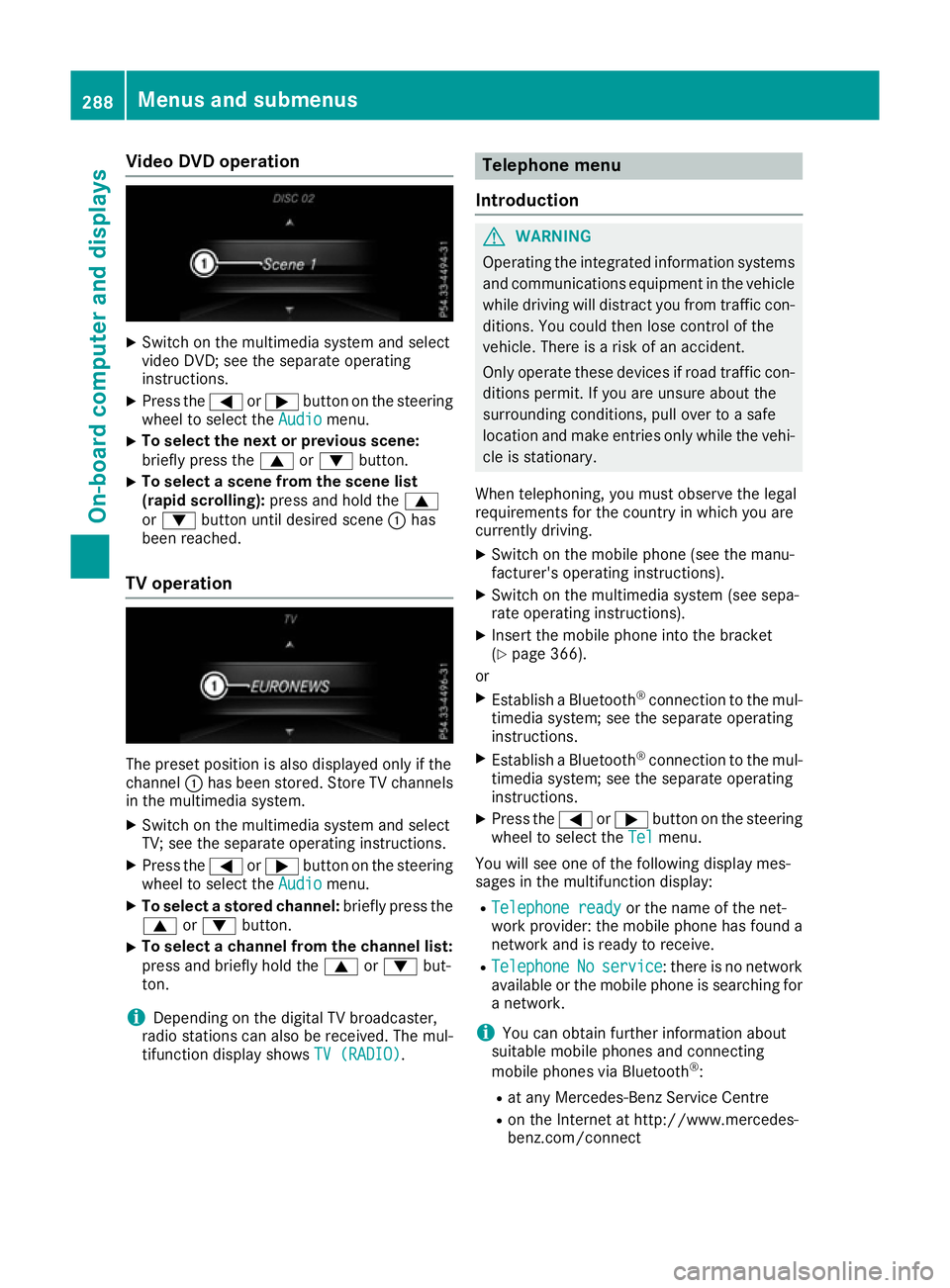
Video DVD operation
X
Switch on the multimedia system and select
video DVD; see the separate operating
instructions.
X Press the =or; button on the steering
wheel to select the Audio
Audio menu.
X To select the next or previous scene:
briefly press the 9or: button.
X To select a scene from the scene list
(rapid scrolling): press and hold the 9
or : button until desired scene :has
been reached.
TV operation The preset position is also displayed only if the
channel :has been stored. Store TV channels
in the multimedia system.
X Switch on the multimedia system and select
TV; see the separate operating instructions.
X Press the =or; button on the steering
wheel to select the Audio
Audio menu.
X To select a stored channel: briefly press the
9 or: button.
X To select a channel from the channel list:
press and briefly hold the
9or: but-
ton.
i Depending on the digital TV broadcaster,
radio stations can also be received. The mul-
tifunction display shows TV (RADIO) TV (RADIO). Telephone menu
Introduction G
WARNING
Operating the integrated information systems and communications equipment in the vehicle
while driving will distract you from traffic con-
ditions. You could then lose control of the
vehicle. There is a risk of an accident.
Only operate these devices if road traffic con-
ditions permit. If you are unsure about the
surrounding conditions, pull over to a safe
location and make entries only while the vehi-
cle is stationary.
When telephoning, you must observe the legal
requirements for the country in which you are
currently driving. X Switch on the mobile phone (see the manu-
facturer's operating instructions).
X Switch on the multimedia system (see sepa-
rate operating instructions).
X Insert the mobile phone into the bracket
(Y page 366).
or X Establish a Bluetooth ®
connection to the mul-
timedia system; see the separate operating
instructions.
X Establish a Bluetooth ®
connection to the mul-
timedia system; see the separate operating
instructions.
X Press the =or; button on the steering
wheel to select the Tel
Tel menu.
You will see one of the following display mes-
sages in the multifunction display:
R Telephone ready Telephone ready or the name of the net-
work provider: the mobile phone has found a
network and is ready to receive.
R Telephone
Telephone No
Noservice
service: there is no network
available or the mobile phone is searching for a network.
i You can obtain further information about
suitable mobile phones and connecting
mobile phones via Bluetooth ®
:
R at any Mercedes-Benz Service Centre
R on the Internet at http://www.mercedes-
benz.com/connect 288
Menus and submenusOn-board computer and displays
Page 296 of 453
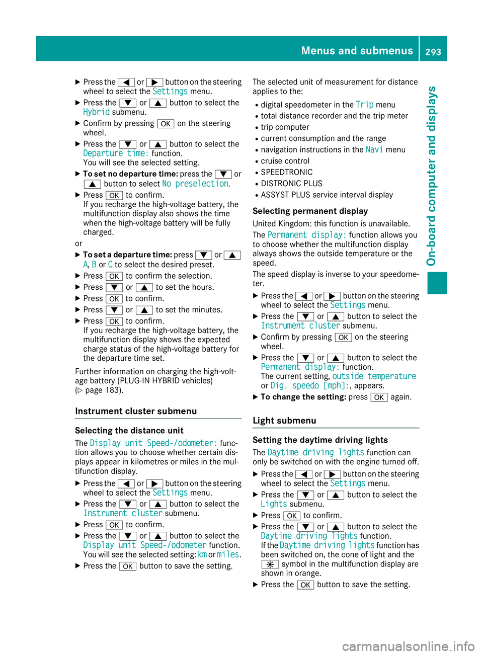
X
Press the =or; button on the steering
wheel to select the Settings
Settings menu.
X Press the :or9 button to select the
Hybrid
Hybrid submenu.
X Confirm by pressing aon the steering
wheel.
X Press the :or9 button to select the
Departure time:
Departure time: function.
You will see the selected setting.
X To set no departure time: press the:or
9 button to select No preselection
No preselection.
X Press ato confirm.
If you recharge the high-voltage battery, the
multifunction display also shows the time
when the high-voltage battery will be fully
charged.
or X To set a departure time: press:or9
A
A, B Bor C
Cto select the desired preset.
X Press ato confirm the selection.
X Press :or9 to set the hours.
X Press ato confirm.
X Press :or9 to set the minutes.
X Press ato confirm.
If you recharge the high-voltage battery, the
multifunction display shows the expected
charge status of the high-voltage battery for
the departure time set.
Further information on charging the high-volt-
age battery (PLUG-IN HYBRID vehicles)
(Y page 183).
Instrument cluster submenu Selecting the distance unit
The Display unit Speed-/odometer: Display unit Speed-/odometer: func-
tion allows you to choose whether certain dis-
plays appear in kilometres or miles in the mul-
tifunction display.
X Press the =or; button on the steering
wheel to select the Settings Settingsmenu.
X Press the :or9 button to select the
Instrument cluster
Instrument cluster submenu.
X Press ato confirm.
X Press the :or9 button to select the
Display unit Speed-/odometer
Display unit Speed-/odometer function.
You will see the selected setting: km
km ormiles miles.
X Press the abutton to save the setting. The selected unit of measurement for distance
applies to the:
R digital speedometer in the Trip Tripmenu
R total distance recorder and the trip meter
R trip computer
R current consumption and the range
R navigation instructions in the Navi
Navimenu
R cruise control
R SPEEDTRONIC
R DISTRONIC PLUS
R ASSYST PLUS service interval display
Selecting permanent display
United Kingdom: this function is unavailable.
The Permanent display: Permanent display: function allows you
to choose whether the multifunction display
always shows the outside temperature or the
speed.
The speed display is inverse to your speedome- ter.
X Press the =or; button on the steering
wheel to select the Settings
Settings menu.
X Press the :or9 button to select the
Instrument cluster Instrument cluster submenu.
X Confirm by pressing aon the steering
wheel.
X Press the :or9 button to select the
Permanent display:
Permanent display: function.
The current setting, outside temperature
outside temperature
or Dig. speedo [mph]:
Dig. speedo [mph]:, appears.
X To change the setting: pressaagain.
Light submenu Setting the daytime driving lights
The Daytime driving lights
Daytime driving lights function can
only be switched on with the engine turned off.
X Press the =or; button on the steering
wheel to select the Settings
Settings menu.
X Press the :or9 button to select the
Lights
Lights submenu.
X Press ato confirm.
X Press the :or9 button to select the
Daytime driving lights
Daytime driving lights function.
If the Daytime
Daytime driving
drivinglights
lightsfunction has
been switched on, the cone of light and the
W symbol in the multifunction display are
shown in orange.
X Press the abutton to save the setting. Menus and submenus
293On-board computer and displays Z
Page 381 of 453
Depending on the operating conditions of the
vehicle, the remaining time or distance until the
next service due date is displayed.
The letter indicates which service is due. A A
stands for a minor service and B
B for a major ser-
vice. A number or another letter may be dis-
played after the letter.
Only for certain countries: the position after the
letter A
A or B Bindicates any necessary additional
maintenance work to be performed. If you notify a qualified specialist workshop of this display,
you will receive a statement on the associated
costs.
The ASSYST PLUS service interval display does
not take into account any periods of time during which the battery is disconnected.
Maintaining the time-dependent service sched-
ule:
X Note down the service due date displayed in
the multifunction display before disconnect-
ing the battery.
or X After reconnecting the battery, subtract the
battery disconnection periods from the ser-
vice date shown on the display. Hiding service messages
X Press the %ora button on the steering
wheel. Displaying service messages
X Switch the ignition on.
X Press the =or; button on the steering
wheel to select the Serv. Serv.menu.
X Press the 9or: button to select the
ASSYST
ASSYST PLUS
PLUSsubmenu and confirm by press-
ing the abutton.
The service due date appears in the multi-
function display. Information about Service
Resetting the ASSYST PLUS service
interval display !
If the ASSYST PLUS service interval display
has been inadvertently reset, this setting can be corrected at a qualified specialist work-
shop.
Have service work carried out as described in the Service Booklet. This may otherwise lead
to increased wear and damage to the major
assemblies or the vehicle.
A qualified specialist workshop, e.g. a
Mercedes-Benz Dealership, will reset the
ASSYST PLUS service interval display after the
service work has been carried out. You can also
obtain further information on maintenance
work, for example.
Special service requirements The prescribed service interval is based on nor-
mal operation of the vehicle. Service work will
need to be performed more often if the vehicle is
operated under arduous conditions or increased loads, for example:
R regular city driving with frequent intermediate
stops
R if the vehicle is primarily used to travel short
distances
R for frequent operation in mountainous terrain
or on poor road surfaces
R if the engine is often left idling for long periods
In these or similar operating conditions, have,
for example, the air filter, engine oil and oil filter changed more frequently. The tyres must be
checked more frequently if the vehicle is oper-
ated under increased loads. Further informationcan be obtained at a qualified specialist work-
shop, e.g. a Mercedes-Benz Service Centre.
Driving abroad An extensive Mercedes-Benz Service network is
also available in other countries. You can obtain further information from any Mercedes-Benz
Service Centre. Care
General notes
H
Environmental note
Dispose of empty packaging and cleaning
cloths in an environmentally responsible man-
ner. 378
CareMaintenance and care
Page 397 of 453
Battery acid is caustic. Avoid contact
with the skin, eyes or clothing.
Wear suitable protective clothing, in
particular gloves, an apron and a
face mask.
Immediately rinse acid splashes off
with clean water. Consult a doctor if
necessary. Wear eye protection.
Keep children away.
Observe this Owner's Manual.
For safety reasons, Mercedes-Benz recom-
mends that you only use batteries which have
been tested and approved for your vehicle by
Mercedes-Benz. These batteries provide
increased impact protection to prevent vehicle
occupants from suffering acid burns should the battery be damaged in the event of an accident.
In order for the battery to achieve the maximum possible service life, it must always be suffi-
ciently charged.
Like other batteries, the vehicle battery may
discharge over time if you do not use the vehicle.In such cases, have the battery disconnected ata qualified specialist workshop. You can also
charge the battery with a charger recommended
by Mercedes-Benz. For more information,
please contact a qualified specialist workshop.
Have the battery charge checked more fre-
quently if you use the vehicle mainly for short
trips or if you leave it standing idle for a lengthy period. Consult a qualified specialist workshop
if you wish to leave your vehicle parked up for a
long period of time.
When you park the vehicle, remove the key if you do not require any electrical consumers. The
vehicle will then use very little energy, thus con- serving battery power.
PLUG-IN HYBRID vehicles: if the battery
charge is sufficient, the high-voltage battery can also supply the 12 V battery. This only happens
if the battery charge of the 12 V battery requires this, e.g. after using electrical consumers for anextended period with the engine switched off. As the on-board voltage is continuously moni-
tored this can also be performed when the
engine is switched off. The battery charge of the
12 V battery and the on-board voltage are
thereby kept stable for longer.
If the power supply has been interrupted, e.g. if the battery was discharged, you will have to:
R set the clock. Information on setting the clock
can be found in the Digital Owner's Manual.
On vehicles with a multimedia system and
navigation system, the clock is set automati-
cally.
R reset the function for folding the exterior mir-
rors in/out automatically, by folding the mir-
rors out once (Y page 118). High-voltage battery - important
safety notes
Only PLUG-IN HYBRID vehicles are equipped
with a high-voltage battery. G
DANGER
The vehicle's high voltage electrical system is under high voltage. If you modify components
in the vehicle's high-voltage electrical system or touch damaged components, you may be
electrocuted. The components in the vehi-
cle's high-voltage electrical system may be
damaged in an accident, although the damage
is not visible. There is a risk of fatal injury.
Do not touch any high-voltage components
after an accident and never modify the vehi-
cle's high-voltage electrical system. Have the vehicle towed away after an accident and the vehicle's high-voltage electrical system
checked by a qualified specialist workshop. G
WARNING
In the event of a vehicle fire, the internal pres- sure of the high-voltage battery could exceeda critical value. In this case, flammable gas
escapes through a vent valve in the vehicle's
underbody. The gas can ignite. There is a risk
of injury.
Leave the danger area immediately. Secure
the danger area at a suitable distance, whilst
observing legal requirements. 394
Battery (vehicle)Breakdown assistance