2015 MERCEDES-BENZ GLE SUV door lock
[x] Cancel search: door lockPage 278 of 453
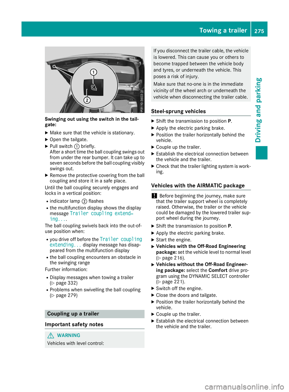
Swinging out using the switch in the tail-
gate:
X Make sure that the vehicle is stationary.
X Open the tailgate.
X Pull switch :briefly.
After a short time the ball coupling swings out from under the rear bumper. It can take up to
seven seconds before the ball coupling visibly
swings out.
X Remove the protective covering from the ball
coupling and store it in a safe place.
Until the ball coupling securely engages and
locks in a vertical position:
R indicator lamp ;flashes
R the multifunction display shows the display
message Trailer coupling extend‐ Trailer coupling extend‐
ing...
ing....
The ball coupling swivels back into the out-of-
use position when:
R you drive off before the Trailer Trailercoupling
coupling
extending...
extending... display message has disap-
peared from the multifunction display
R the ball coupling encounters an obstacle in
the swinging range
Further information:
R Display messages when towing a trailer
(Y page 332)
R Problems when swivelling the ball coupling
(Y page 279) Coupling up a trailer
Important safety notes G
WARNING
Vehicles with level control: If you disconnect the trailer cable, the vehicle
is lowered. This can cause you or others to
become trapped between the vehicle body
and tyres, or underneath the vehicle. This
poses a risk of injury.
Make sure that no-one is in the immediate
vicinity of the wheel arch or underneath the
vehicle when disconnecting the trailer cable.
Steel-sprung vehicles X
Shift the transmission to position P.
X Apply the electric parking brake.
X Position the trailer horizontally behind the
vehicle.
X Couple up the trailer.
X Establish the electrical connection between
the vehicle and the trailer.
X Check that the trailer lighting system is work-
ing.
Vehicles with the AIRMATIC package !
Before beginning the journey, make sure
that the trailer support wheel is completely
raised. Otherwise, the trailer or the vehicle
could be damaged by the lowered trailer sup- port wheel during the journey.
X Shift the transmission to position P.
X Apply the electric parking brake.
X Start the engine.
X Vehicles with the Off-Road Engineering
package:
set the vehicle level to normal level
(Y page 216).
X Vehicles without the Off-Road Engineer-
ing package:
select theComfortdrive pro-
gram using the DYNAMIC SELECT controller
(Y page 221).
X Switch off the engine.
X Close the doors and tailgate.
X Position the trailer horizontally behind the
vehicle.
X Couple up the trailer.
X Establish the electrical connection between
the vehicle and the trailer. Towing a trailer
275Driving and parking Z
Page 280 of 453
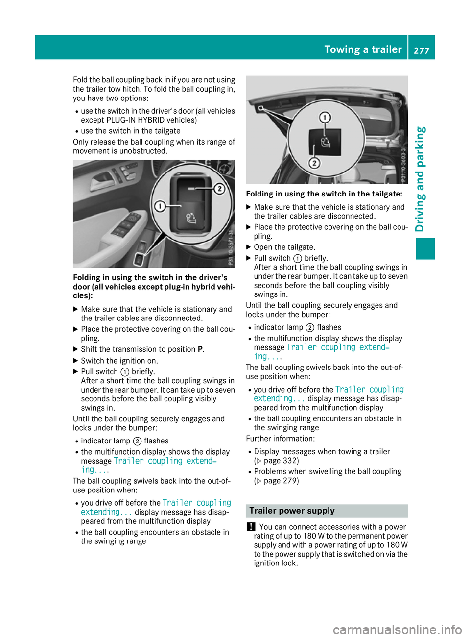
Fold the ball coupling back in if you are not using
the trailer tow hitch. To fold the ball coupling in,
you have two options:
R use the switch in the driver's door (all vehicles
except PLUG-IN HYBRID vehicles)
R use the switch in the tailgate
Only release the ball coupling when its range of
movement is unobstructed. Folding in using the switch in the driver's
door (all vehicles except plug-in hybrid vehi-
cles):
X Make sure that the vehicle is stationary and
the trailer cables are disconnected.
X Place the protective covering on the ball cou-
pling.
X Shift the transmission to position P.
X Switch the ignition on.
X Pull switch :briefly.
After a short time the ball coupling swings in
under the rear bumper. It can take up to seven seconds before the ball coupling visibly
swings in.
Until the ball coupling securely engages and
locks under the bumper:
R indicator lamp ;flashes
R the multifunction display shows the display
message Trailer coupling extend‐
Trailer coupling extend‐
ing... ing....
The ball coupling swivels back into the out-of-
use position when:
R you drive off before the Trailer
Trailer coupling
coupling
extending... extending... display message has disap-
peared from the multifunction display
R the ball coupling encounters an obstacle in
the swinging range Folding in using the switch in the tailgate:
X Make sure that the vehicle is stationary and
the trailer cables are disconnected.
X Place the protective covering on the ball cou-
pling.
X Open the tailgate.
X Pull switch :briefly.
After a short time the ball coupling swings in
under the rear bumper. It can take up to seven seconds before the ball coupling visibly
swings in.
Until the ball coupling securely engages and
locks under the bumper:
R indicator lamp ;flashes
R the multifunction display shows the display
message Trailer coupling extend‐
Trailer coupling extend‐
ing... ing....
The ball coupling swivels back into the out-of-
use position when:
R you drive off before the Trailer
Trailercoupling
coupling
extending...
extending... display message has disap-
peared from the multifunction display
R the ball coupling encounters an obstacle in
the swinging range
Further information:
R Display messages when towing a trailer
(Y page 332)
R Problems when swivelling the ball coupling
(Y page 279) Trailer power supply
! You can connect accessories with a power
rating of up to 180 W to the permanent power supply and with a power rating of up to 180 Wto the power supply that is switched on via the
ignition lock. Towing a trailer
277Driving and parking Z
Page 283 of 453
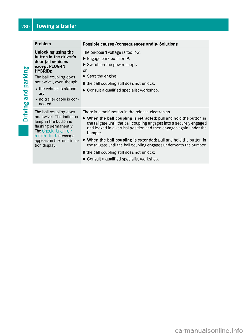
Problem
Possible causes/consequences and
M
MSolutions Unlocking using the
button in the driver's
door (all vehicles
except PLUG-IN
HYBRID):
The ball coupling does
not swivel, even though:
R the vehicle is station-
ary
R no trailer cable is con-
nected The on-board voltage is too low.
X Engage park position P.
X Switch on the power supply.
or X Start the engine.
If the ball coupling still does not unlock: X Consult a qualified specialist workshop. The ball coupling does
not swivel. The indicator
lamp in the button is
flashing permanently.
The
Check trailer Check trailer
hitch lock
hitch lock message
appears in the multifunc- tion display. There is a malfunction in the release electronics.
X When the ball coupling is retracted: pull and hold the button in
the tailgate until the ball coupling engages into a securely engaged
and locked in a vertical position and then engages again under the
bumper.
X When the ball coupling is extended: pull and hold the button in
the tailgate until the ball coupling engages underneath the bumper.
If the ball coupling still does not unlock:
X Consult a qualified specialist workshop. 280
Towing a trailerDriving and parking
Page 297 of 453
Further information on daytime driving lights
(Y page 122).
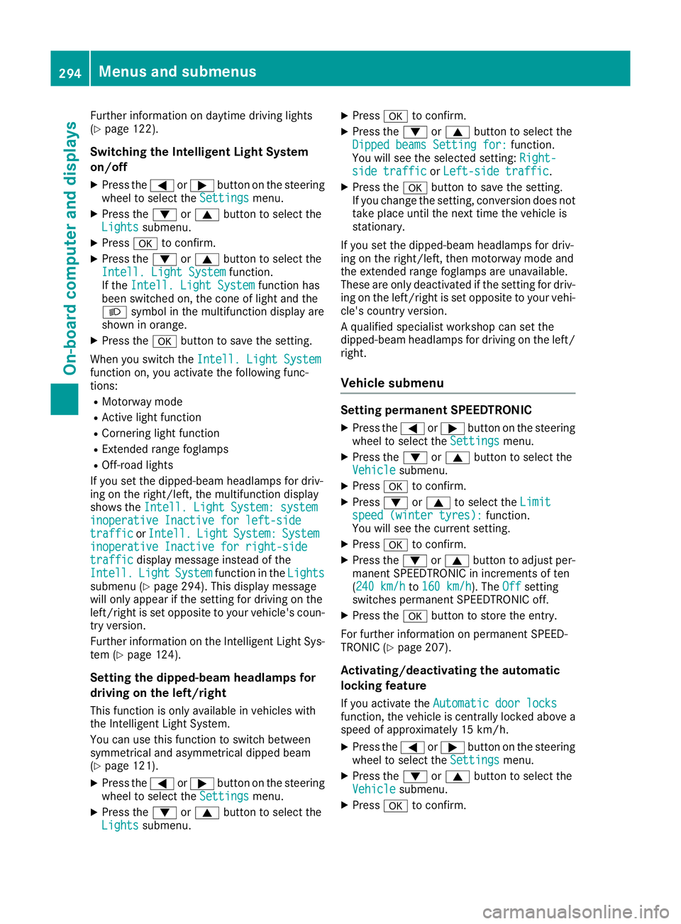
Switching the Intelligent Light System
on/off
X Press the =or; button on the steering
wheel to select the Settings Settingsmenu.
X Press the :or9 button to select the
Lights
Lights submenu.
X Press ato confirm.
X Press the :or9 button to select the
Intell. Light System
Intell. Light System function.
If the Intell. Light System
Intell. Light System function has
been switched on, the cone of light and the
L symbol in the multifunction display are
shown in orange.
X Press the abutton to save the setting.
When you switch the Intell. Light System
Intell. Light System
function on, you activate the following func-
tions:
R Motorway mode
R Active light function
R Cornering light function
R Extended range foglamps
R Off-road lights
If you set the dipped-beam headlamps for driv-
ing on the right/left, the multifunction display
shows the Intell. Light System: system
Intell. Light System: system
inoperative Inactive for left-side inoperative Inactive for left-side
traffic traffic orIntell.
Intell. Light
LightSystem:
System: System
System
inoperative Inactive for right-side
inoperative Inactive for right-side
traffic traffic display message instead of the
Intell.
Intell. Light
LightSystem
System function in the Lights
Lights
submenu (Y page 294). This display message
will only appear if the setting for driving on the
left/right is set opposite to your vehicle's coun-
try version.
Further information on the Intelligent Light Sys-
tem (Y page 124).
Setting the dipped-beam headlamps for
driving on the left/right
This function is only available in vehicles with
the Intelligent Light System.
You can use this function to switch between
symmetrical and asymmetrical dipped beam
(Y page 121).
X Press the =or; button on the steering
wheel to select the Settings Settingsmenu.
X Press the :or9 button to select the
Lights
Lights submenu. X
Press ato confirm.
X Press the :or9 button to select the
Dipped beams Setting for: Dipped beams Setting for: function.
You will see the selected setting: Right- Right-
side traffic
side traffic orLeft-side traffic
Left-side traffic.
X Press the abutton to save the setting.
If you change the setting, conversion does not
take place until the next time the vehicle is
stationary.
If you set the dipped-beam headlamps for driv-
ing on the right/left, then motorway mode and
the extended range foglamps are unavailable.
These are only deactivated if the setting for driv-
ing on the left/right is set opposite to your vehi- cle's country version.
A qualified specialist workshop can set the
dipped-beam headlamps for driving on the left/
right.
Vehicle submenu Setting permanent SPEEDTRONIC
X Press the =or; button on the steering
wheel to select the Settings Settingsmenu.
X Press the :or9 button to select the
Vehicle
Vehicle submenu.
X Press ato confirm.
X Press :or9 to select the Limit
Limit
speed (winter tyres):
speed (winter tyres): function.
You will see the current setting.
X Press ato confirm.
X Press the :or9 button to adjust per-
manent SPEEDTRONIC in increments of ten
(240 km/h 240 km/h to160 km/h 160 km/h ). TheOff
Offsetting
switches permanent SPEEDTRONIC off.
X Press the abutton to store the entry.
For further information on permanent SPEED-
TRONIC (Y page 207).
Activating/deactivating the automatic
locking feature If you activate the Automatic door locks Automatic door locks
function, the vehicle is centrally locked above a
speed of approximately 15 km/h.
X Press the =or; button on the steering
wheel to select the Settings
Settingsmenu.
X Press the :or9 button to select the
Vehicle
Vehicle submenu.
X Press ato confirm. 294
Menus and submenusOn-board computer and displays
Page 298 of 453
X
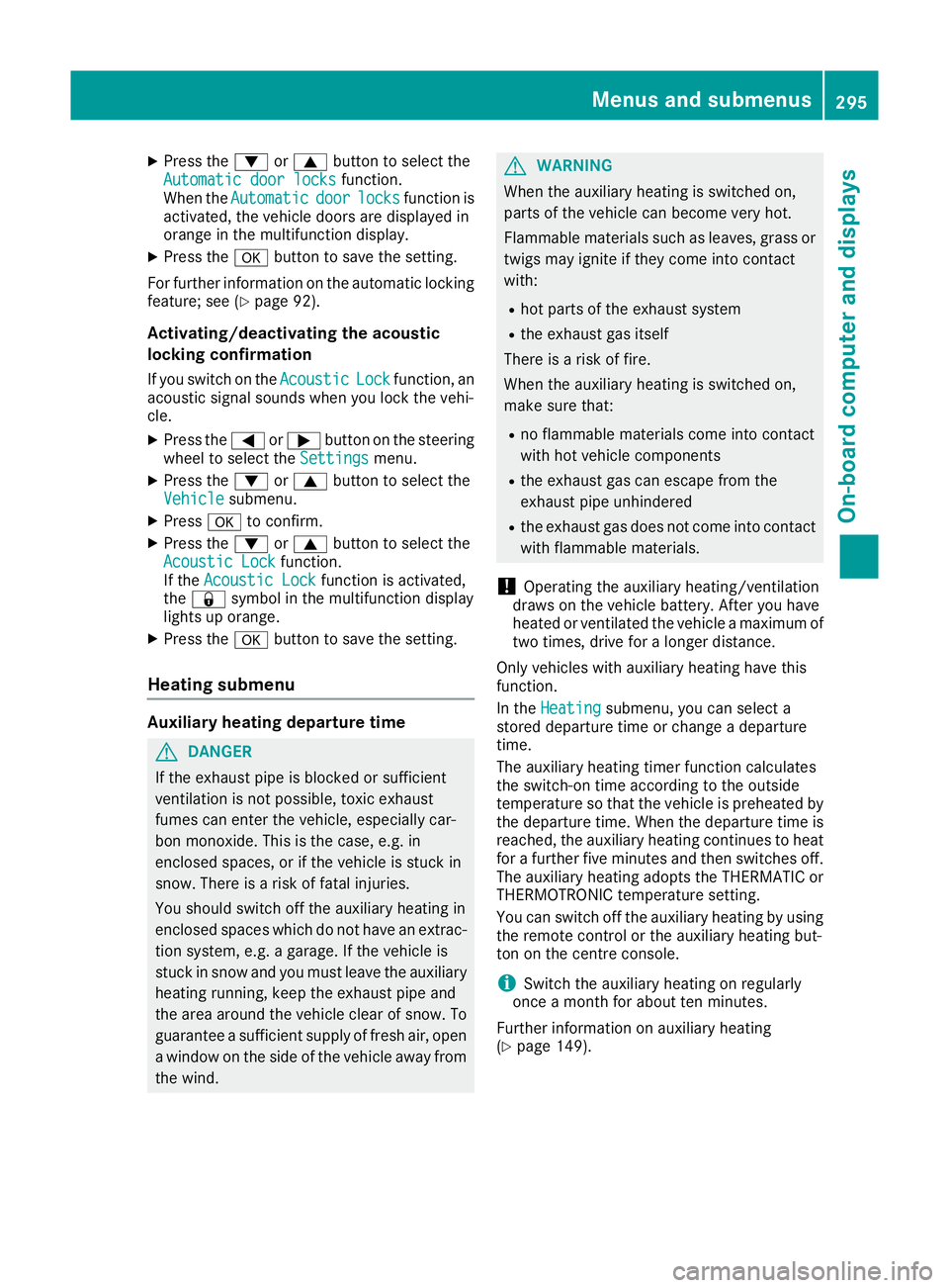
Press the :or9 button to select the
Automatic door locks
Automatic door locks function.
When the Automatic
Automatic door
doorlocks
locks function is
activated, the vehicle doors are displayed in
orange in the multifunction display.
X Press the abutton to save the setting.
For further information on the automatic locking
feature; see (Y page 92).
Activating/deactivating the acoustic
locking confirmation
If you switch on the Acoustic
Acoustic Lock Lockfunction, an
acoustic signal sounds when you lock the vehi-
cle.
X Press the =or; button on the steering
wheel to select the Settings
Settings menu.
X Press the :or9 button to select the
Vehicle
Vehicle submenu.
X Press ato confirm.
X Press the :or9 button to select the
Acoustic Lock Acoustic Lock function.
If the Acoustic Lock
Acoustic Lock function is activated,
the & symbol in the multifunction display
lights up orange.
X Press the abutton to save the setting.
Heating submenu Auxiliary heating departure time
G
DANGER
If the exhaust pipe is blocked or sufficient
ventilation is not possible, toxic exhaust
fumes can enter the vehicle, especially car-
bon monoxide. This is the case, e.g. in
enclosed spaces, or if the vehicle is stuck in
snow. There is a risk of fatal injuries.
You should switch off the auxiliary heating in
enclosed spaces which do not have an extrac- tion system, e.g. a garage. If the vehicle is
stuck in snow and you must leave the auxiliary
heating running, keep the exhaust pipe and
the area around the vehicle clear of snow. To guarantee a sufficient supply of fresh air, open
a window on the side of the vehicle away from the wind. G
WARNING
When the auxiliary heating is switched on,
parts of the vehicle can become very hot.
Flammable materials such as leaves, grass or twigs may ignite if they come into contact
with:
R hot parts of the exhaust system
R the exhaust gas itself
There is a risk of fire.
When the auxiliary heating is switched on,
make sure that:
R no flammable materials come into contact
with hot vehicle components
R the exhaust gas can escape from the
exhaust pipe unhindered
R the exhaust gas does not come into contact
with flammable materials.
! Operating the auxiliary heating/ventilation
draws on the vehicle battery. After you have
heated or ventilated the vehicle a maximum of two times, drive for a longer distance.
Only vehicles with auxiliary heating have this
function.
In the Heating Heating submenu, you can select a
stored departure time or change a departure
time.
The auxiliary heating timer function calculates
the switch-on time according to the outside
temperature so that the vehicle is preheated by the departure time. When the departure time isreached, the auxiliary heating continues to heat
for a further five minutes and then switches off. The auxiliary heating adopts the THERMATIC orTHERMOTRONIC temperature setting.
You can switch off the auxiliary heating by using
the remote control or the auxiliary heating but-
ton on the centre console.
i Switch the auxiliary heating on regularly
once a month for about ten minutes.
Further information on auxiliary heating
(Y page 149). Menus and submenus
295On-board computer and displays Z
Page 337 of 453
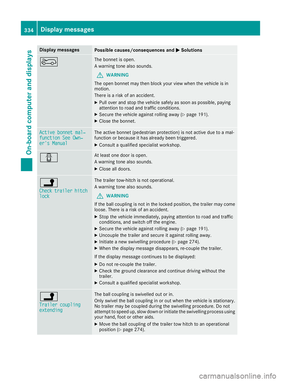
Display messages
Possible causes/consequences and
M
MSolutions ? The bonnet is open.
A warning tone also sounds.
G WARNING
The open bonnet may then block your view when the vehicle is in
motion.
There is a risk of an accident.
X Pull over and stop the vehicle safely as soon as possible, paying
attention to road and traffic conditions.
X Secure the vehicle against rolling away (Y page 191).
X Close the bonnet. Active bonnet mal‐ Active bonnet mal‐
function See Own‐ function See Own‐
er's Manual er's Manual The active bonnet (pedestrian protection) is not active due to a mal-
function or because it has already been triggered.
X Consult a qualified specialist workshop. C At least one door is open.
A warning tone also sounds.
X Close all doors. j
Check Check
trailer
trailer hitch
hitch
lock
lock The trailer tow-hitch is not operational.
A warning tone also sounds.
G WARNING
If the ball coupling is not in the locked position, the trailer may come
loose. There is a risk of an accident.
X Stop the vehicle immediately, paying attention to road and traffic
conditions, and switch off the engine.
X Secure the vehicle against rolling away (Y page 191).
X Uncouple the trailer and secure it against rolling away.
X Initiate a new swivelling procedure (Y page 274).
X When the display message disappears, re-couple the trailer.
If the display message continues to be displayed: X Do not re-couple the trailer.
X Check the ground clearance and continue driving without the
trailer.
X Consult a qualified specialist workshop. j
Trailer coupling Trailer coupling
extending extending The ball coupling is swivelled out or in.
Only swivel the ball coupling in or out when the vehicle is stationary.
No trailer may be coupled during the swivelling procedure. Do not
attempt to speed up, slow down or initiate the swivelling process using your hand, foot or other aids.
X Move the ball coupling of the trailer tow hitch to an operational
position (Y page 274). 334
Display
messagesOn-board computer and displays
Page 370 of 453
cle. You can then no longer make calls using the
hands-free system.
If a call is active and you remove the key from
the ignition lock, the conversation is transferred over to the mobile phone. It is then possible to
continue the conversation on the mobile phone. Garage door opener
General notes The HomeLink
®
garage door opener integrated
in the rear-view mirror allows you to operate up
to three different door and gate systems.
Once programmed, the integrated garage door
opener in the rear-view mirror will assume the
function of the garage door system's remote
control. Please also read the operating instruc-
tions for the garage door system.
When programming a garage door opener, park
the vehicle outside the garage. Do not run the
engine while programming.
The garage door opener is only available for cer- tain countries. Observe the legal requirements
for each individual country.
The HomeLink ®
garage door opener is compat-
ible with most European garage and gate opener
drives. More information on HomeLink ®
and/or
compatible products is available:
R at a qualified specialist workshop
R via the HomeLink ®
Hotline
(0) 08000 466 354 65 or alternatively
+49 (0) 6838 907-277
R on the Internet at http://www.homelink.com
Important safety notes G
WARNING
When you operate or program the garage door with the integrated garage door opener, per-
sons in the range of movement of the garage
door can become trapped or struck by the
garage door. There is a risk of injury.
When using the integrated garage door
opener, always make sure that nobody is
within the range of movement of the garage
door. G
WARNING
Combustion engines emit poisonous exhaust
gases such as carbon monoxide. Inhaling
these exhaust gases leads to poisoning. There is a risk of fatal injury. Therefore never leave
the engine running in enclosed spaces with-
out sufficient ventilation.
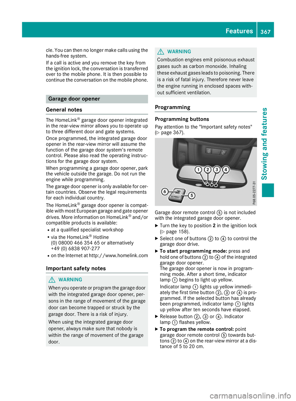
Programming Programming buttons
Pay attention to the "Important safety notes"
(Y page 367). Garage door remote control
Ais not included
with the integrated garage door opener.
X Turn the key to position 2in the ignition lock
(Y page 158).
X Select one of buttons ;to? to control the
garage door drive.
X To start programming mode: press and
hold one of buttons ;to? of the integrated
garage door opener.
The garage door opener is now in program-
ming mode. After a short time, indicator
lamp :begins to light up yellow.
Indicator lamp :lights up yellow immedi-
ately the first time button ;,=or? is pro-
grammed. If the selected button has already
been programmed, indicator lamp :lights
up yellow after ten seconds have elapsed.
X Release button ;,=or?. Indicator
lamp :flashes yellow.
X To program the remote control: point
garage door remote control Atowards but-
tons ;to? on the rear-view mirror at a dis-
tance of 5 to 20 cm. Features
367Stowing and features Z
Page 371 of 453
X
Press and hold button Bon remote control
A until indicator lamp :lights up green.
When indicator lamp :lights up green: pro-
gramming is finished.
When indicator lamp :flashes green: pro-
gramming was successful. The next step is to synchronise the rolling code (Y page 368).
X Release button Bof remote control Aof the
garage door drive.
If indicator lamp :lights up red: repeat the
programming process for the corresponding
button on the rear-view mirror. When doing
so, vary the distance between remote control A and the rear-view mirror.
The required distance between remote con-
trol Aand the integrated garage door opener
depends on the garage door drive system.
Several attempts may be required. You
should test every position for at least
25 seconds before trying another position.
Synchronising the rolling code
Observe the "Important safety notes"
(Y page 367).
If the garage door system uses a rolling code,
you will also have to synchronise the garage
door system with the integrated garage door
opener in the rear-view mirror. To do this, you
will need to use the programming button on the door drive control panel. The programming but-
ton may be placed at different locations depend- ing on the manufacturer. It is usually located on
the door drive unit on the garage ceiling.
Familiarise yourself with the garage door drive
operating instructions, e.g. under "Program-
ming of additional remote controls", before car-
rying out the following steps.
Your vehicle must be within range of the garage
door or gate opener drive. Make sure that nei-
ther your vehicle nor any persons/objects are
present within the sweep of the door or gate.
X Turn the key to position 2in the ignition lock
(Y page 158).
X Get out of the vehicle.
X Press the programming button on the door
drive unit.
Usually, you now have 30 seconds to initiate
the next step. X
Get into the vehicle.
X Press previously programmed button ;,=
or ? of the integrated garage door opener
until the door closes.
The rolling code synchronisation is then com- plete.
Problems when programming
If you have problems when programming the
integrated garage door opener, please note the following:
R Check the transmitter frequency used by
garage door drive remote control Aand
whether it is supported. The transmitter fre-
quency can usually be found on the back of
the garage door drive remote control.
R Replace the batteries in garage door remote
control A. This increases the likelihood that
garage door remote control Awill transmit a
strong and precise signal to the integrated
garage door opener in the rear-view mirror.
R When programming, hold remote control A
at varying distances and angles from the but-
ton which you are programming. Try various
angles at a distance between 5and 20 cm or
at the same angle but at varying distances.
R If there is another remote control for the same
garage door drive, perform the programming
steps again using this remote control. Before performing these steps, make sure that new
batteries have been fitted in garage door drive
remote control A.
R Note that some remote controls transmit only
for a limited period (the indicator lamp on the remote control goes out). Press button Bon
remote control Aagain before transmission
ends.
R Align the aerial cable of the garage door
opener unit. This can improve signal recep-
tion/transmission.
Opening or closing the garage door Once programmed, the integrated garage door
opener will assume the function of the garage
door system's remote control. Please also read
the operating instructions for the garage door
system. 368
FeaturesSto
wing an d features