2015 MERCEDES-BENZ GLE SUV tailgate
[x] Cancel search: tailgatePage 279 of 453
X
Check that the trailer lighting system is work-
ing.
X Push the combination switch upwards and
downwards and check whether the corre-
sponding turn signal on the trailer is flashing.
A connected trailer is only detected when the
electrical connection is established correctly
and when the lighting system is working prop-
erly. The function of other systems also depends on this, for example:
R ESP ®
R PARKTRONIC
R Active Parking Assist
R Active Blind Spot Assist
R Active Lane Keeping Assist
i Vehicles with the AIRMATIC package:
if
you couple up a trailer, the vehicle initially
remains at the selected level of the drive pro- gram set. Observe the following when cou-
pling up a trailer:
R If the normal level was not selected previ-
ously, the vehicle automatically adopts the
normal level starting from a speed of
30 km/h. Even at higher speeds, it does not drop below the normal level.
R Vehicle levels below the normal level are
not available.
R The raised level is available up to a speed of
30 km/h.
R This also applies when using accessories
that are plugged into the socket of the
trailer tow hitch (e.g. a bicycle rack).
R Before driving with a trailer, please observe
the information on the trailer support
wheel. Uncoupling a trailer
Important safety notes G
WARNING
If you uncouple a trailer with an engaged over- run brake, you could trap your hand between
the vehicle and the trailer drawbar. This poses a risk of injury.
Do not uncouple a trailer with an engaged
overrun brake. G
WARNING
Vehicles with level control:
If you disconnect the trailer cable, the vehicle is lowered. This can cause you or others to
become trapped between the vehicle body
and tyres, or underneath the vehicle. This
poses a risk of injury.
Make sure that no-one is in the immediate
vicinity of the wheel arch or underneath the
vehicle when disconnecting the trailer cable.
! Do not disconnect a trailer with an engaged
overrun brake. Otherwise, your vehicle could
be damaged by the rebounding of the overrun
brake.
! Remove the adapter cable before folding in
the ball coupling. You could otherwise dam-
age the rear bumper and the adapter cable.
Steel-sprung vehicles X
Shift the transmission to position P.
X Apply the electric parking brake.
X Secure the trailer against rolling away.
X Remove the trailer cable and decouple the
trailer.
Vehicles with the AIRMATIC package X
Shift the transmission to position P.
X Apply the electric parking brake.
X Start the engine.
X Close the doors and tailgate.
X Secure the trailer against rolling away.
X Remove the trailer cable and decouple the
trailer.
X Switch off the engine. Swinging the ball coupling in
! Do not attempt to speed the up the swing-
out procedure by applying additional pressure
with your foot. The system could otherwise be
mechanically damaged. 276
Towing a trailerDriving and parking
Page 280 of 453
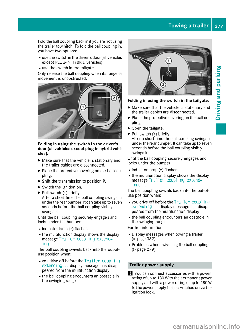
Fold the ball coupling back in if you are not using
the trailer tow hitch. To fold the ball coupling in,
you have two options:
R use the switch in the driver's door (all vehicles
except PLUG-IN HYBRID vehicles)
R use the switch in the tailgate
Only release the ball coupling when its range of
movement is unobstructed. Folding in using the switch in the driver's
door (all vehicles except plug-in hybrid vehi-
cles):
X Make sure that the vehicle is stationary and
the trailer cables are disconnected.
X Place the protective covering on the ball cou-
pling.
X Shift the transmission to position P.
X Switch the ignition on.
X Pull switch :briefly.
After a short time the ball coupling swings in
under the rear bumper. It can take up to seven seconds before the ball coupling visibly
swings in.
Until the ball coupling securely engages and
locks under the bumper:
R indicator lamp ;flashes
R the multifunction display shows the display
message Trailer coupling extend‐
Trailer coupling extend‐
ing... ing....
The ball coupling swivels back into the out-of-
use position when:
R you drive off before the Trailer
Trailer coupling
coupling
extending... extending... display message has disap-
peared from the multifunction display
R the ball coupling encounters an obstacle in
the swinging range Folding in using the switch in the tailgate:
X Make sure that the vehicle is stationary and
the trailer cables are disconnected.
X Place the protective covering on the ball cou-
pling.
X Open the tailgate.
X Pull switch :briefly.
After a short time the ball coupling swings in
under the rear bumper. It can take up to seven seconds before the ball coupling visibly
swings in.
Until the ball coupling securely engages and
locks under the bumper:
R indicator lamp ;flashes
R the multifunction display shows the display
message Trailer coupling extend‐
Trailer coupling extend‐
ing... ing....
The ball coupling swivels back into the out-of-
use position when:
R you drive off before the Trailer
Trailercoupling
coupling
extending...
extending... display message has disap-
peared from the multifunction display
R the ball coupling encounters an obstacle in
the swinging range
Further information:
R Display messages when towing a trailer
(Y page 332)
R Problems when swivelling the ball coupling
(Y page 279) Trailer power supply
! You can connect accessories with a power
rating of up to 180 W to the permanent power supply and with a power rating of up to 180 Wto the power supply that is switched on via the
ignition lock. Towing a trailer
277Driving and parking Z
Page 282 of 453
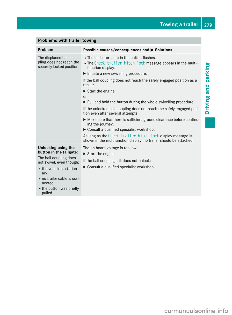
Problems with trailer towing
Problem
Possible causes/consequences and
M
MSolutions The displaced ball cou-
pling does not reach the
securely locked position. R
The indicator lamp in the button flashes.
R The Check trailer hitch lock Check trailer hitch lock message appears in the multi-
function display.
X Initiate a new swivelling procedure.
If the ball coupling does not reach the safely engaged position as a
result:
X Start the engine
or
X Pull and hold the button during the whole swivelling procedure.
If the unlocked ball coupling does not reach the safely engaged posi- tion even after several attempts:
X Make sure that there is sufficient ground clearance before continu-
ing the journey.
X Consult a qualified specialist workshop.
As long as the Check trailer hitch lock
Check trailer hitch lock display message is
shown in the multifunction display, no trailer should be attached. Unlocking using the
button in the tailgate:
The ball coupling does
not swivel, even though:
R
the vehicle is station-
ary
R no trailer cable is con-
nected
R the button was briefly
pulled The on-board voltage is too low.
X Start the engine.
If the ball coupling still does not unlock:
X Consult a qualified specialist workshop. Towing a trailer
279Driving and parking Z
Page 283 of 453
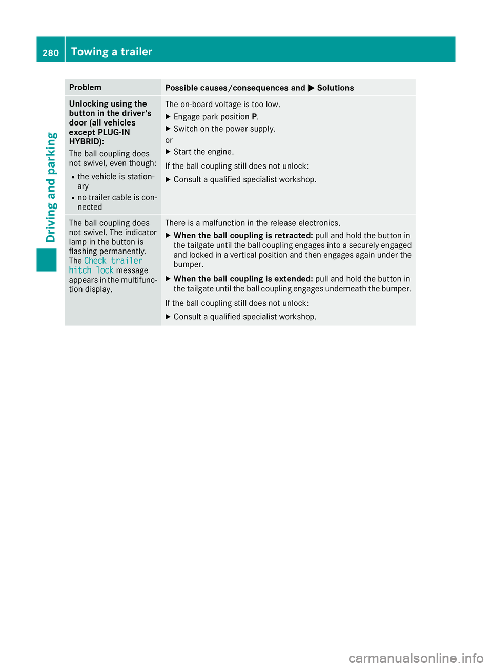
Problem
Possible causes/consequences and
M
MSolutions Unlocking using the
button in the driver's
door (all vehicles
except PLUG-IN
HYBRID):
The ball coupling does
not swivel, even though:
R the vehicle is station-
ary
R no trailer cable is con-
nected The on-board voltage is too low.
X Engage park position P.
X Switch on the power supply.
or X Start the engine.
If the ball coupling still does not unlock: X Consult a qualified specialist workshop. The ball coupling does
not swivel. The indicator
lamp in the button is
flashing permanently.
The
Check trailer Check trailer
hitch lock
hitch lock message
appears in the multifunc- tion display. There is a malfunction in the release electronics.
X When the ball coupling is retracted: pull and hold the button in
the tailgate until the ball coupling engages into a securely engaged
and locked in a vertical position and then engages again under the
bumper.
X When the ball coupling is extended: pull and hold the button in
the tailgate until the ball coupling engages underneath the bumper.
If the ball coupling still does not unlock:
X Consult a qualified specialist workshop. 280
Towing a trailerDriving and parking
Page 336 of 453
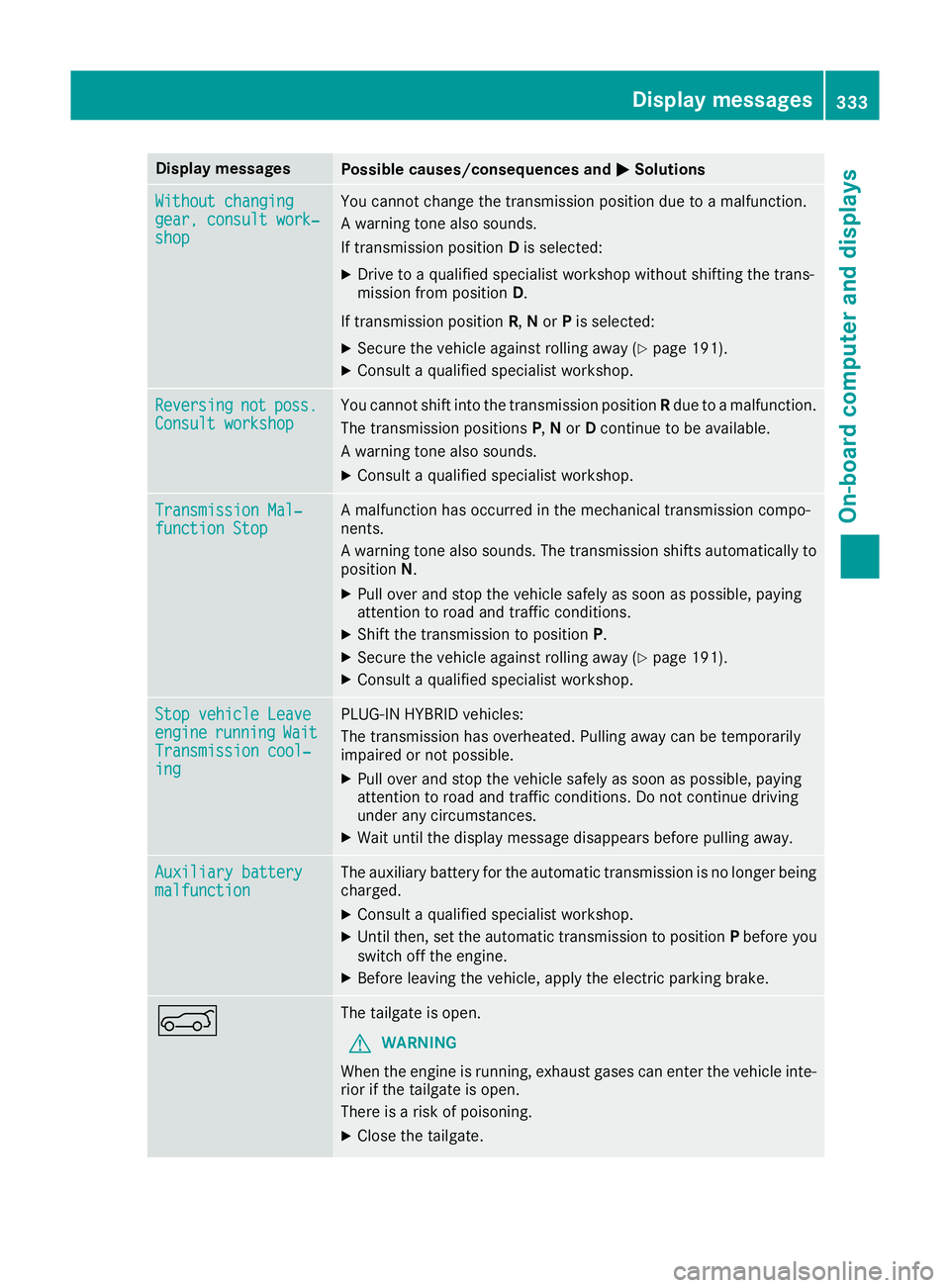
Display messages
Possible causes/consequences and
M
MSolutions Without changing
Without changing
gear, consult work‐ gear, consult work‐
shop shop You cannot change the transmission position due to a malfunction.
A warning tone also sounds.
If transmission position
Dis selected:
X Drive to a qualified specialist workshop without shifting the trans-
mission from position D.
If transmission position R,Nor Pis selected:
X Secure the vehicle against rolling away (Y page 191).
X Consult a qualified specialist workshop. Reversing Reversing
not
notposs.
poss.
Consult workshop
Consult workshop You cannot shift into the transmission position
Rdue to a malfunction.
The transmission positions P,N or Dcontinue to be available.
A warning tone also sounds.
X Consult a qualified specialist workshop. Transmission Mal‐
Transmission Mal‐
function Stop function Stop A malfunction has occurred in the mechanical transmission compo-
nents.
A warning tone also sounds. The transmission shifts automatically to position N.
X Pull over and stop the vehicle safely as soon as possible, paying
attention to road and traffic conditions.
X Shift the transmission to position P.
X Secure the vehicle against rolling away (Y page 191).
X Consult a qualified specialist workshop. Stop vehicle Leave Stop vehicle Leave
engine engine
running
running Wait
Wait
Transmission cool‐
Transmission cool‐
ing ing PLUG-IN HYBRID vehicles:
The transmission has overheated. Pulling away can be temporarily
impaired or not possible.
X Pull over and stop the vehicle safely as soon as possible, paying
attention to road and traffic conditions. Do not continue driving
under any circumstances.
X Wait until the display message disappears before pulling away. Auxiliary battery Auxiliary battery
malfunction malfunction The auxiliary battery for the automatic transmission is no longer being
charged.
X Consult a qualified specialist workshop.
X Until then, set the automatic transmission to position Pbefore you
switch off the engine.
X Before leaving the vehicle, apply the electric parking brake. A The tailgate is open.
G WARNING
When the engine is running, exhaust gases can enter the vehicle inte- rior if the tailgate is open.
There is a risk of poisoning.
X Close the tailgate. Display
messages
333On-board computer and displays Z
Page 354 of 453
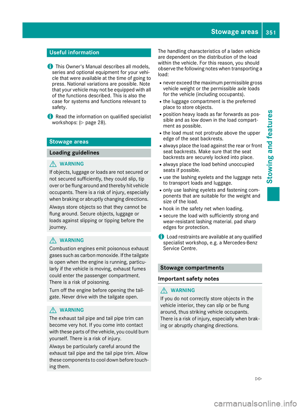
Useful information
i This Owner's Manual describes all models,
series and optional equipment for your vehi-
cle that were available at the time of going to
press. National variations are possible. Note
that your vehicle may not be equipped with all
of the functions described. This is also the
case for systems and functions relevant to
safety.
i Read the information on qualified specialist
workshops: (Y page 28). Stowage areas
Loading guidelines
G
WARNING
If objects, luggage or loads are not secured or not secured sufficiently, they could slip, tip
over or be flung around and thereby hit vehicle
occupants. There is a risk of injury, especially when braking or abruptly changing directions.
Always store objects so that they cannot be
flung around. Secure objects, luggage or
loads against slipping or tipping before the
journey. G
WARNING
Combustion engines emit poisonous exhaust
gases such as carbon monoxide. If the tailgate is open when the engine is running, particu-
larly if the vehicle is moving, exhaust fumes
could enter the passenger compartment.
There is a risk of poisoning.
Turn off the engine before opening the tail-
gate. Never drive with the tailgate open. G
WARNING
The exhaust tail pipe and tail pipe trim can
become very hot. If you come into contact
with these parts of the vehicle, you could burn
yourself. There is a risk of injury.
Always be particularly careful around the
exhaust tail pipe and the tail pipe trim. Allow
these components to cool down before touch-
ing them. The handling characteristics of a laden vehicle
are dependent on the distribution of the load
within the vehicle. For this reason, you should
observe the following notes when transporting a
load:
R never exceed the maximum permissible gross
vehicle weight or the permissible axle loads
for the vehicle (including occupants).
R the luggage compartment is the preferred
place to store objects.
R position heavy loads as far forwards as pos-
sible and as low down in the load compart-
ment as possible.
R the load must not protrude above the upper
edge of the seat backrests.
R always place the load against the rear or front
seat backrests. Make sure that the seat
backrests are securely locked into place.
R always place the load behind unoccupied
seats if possible.
R use the lashing eyelets and the luggage nets
to transport loads and luggage.
R only use lashing eyelets and fastening com-
ponents that are suitable for the weight and
size of the load.
R hook in the safety net when loading.
R secure the load with sufficiently strong and
wear-resistant lashing material. pad sharp
edges for protection.
i Load restraints are available at any qualified
specialist workshop, e.g. a Mercedes-Benz
Service Centre. Stowage compartments
Important safety notes G
WARNING
If you do not correctly store objects in the
vehicle interior, they can slip or be flung
around, thus striking vehicle occupants.
There is a risk of injury, especially when brak- ing or abruptly changing directions. Stowage areas
351Stowing and features
Z
Page 361 of 453
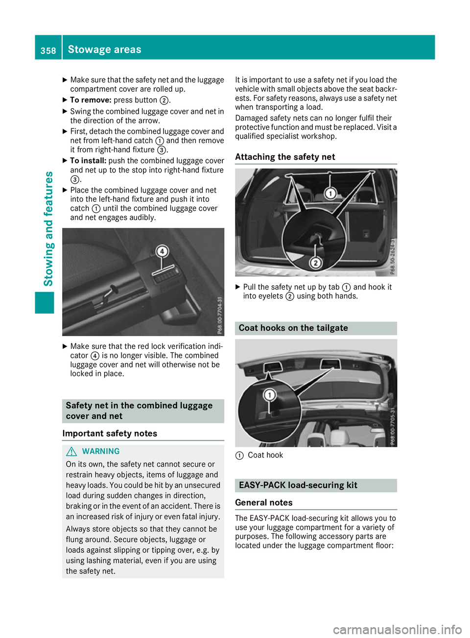
X
Make sure that the safety net and the luggage
compartment cover are rolled up.
X To remove: press button ;.
X Swing the combined luggage cover and net in
the direction of the arrow.
X First, detach the combined luggage cover and
net from left-hand catch :and then remove
it from right-hand fixture =.
X To install: push the combined luggage cover
and net up to the stop into right-hand fixture
=.
X Place the combined luggage cover and net
into the left-hand fixture and push it into
catch :until the combined luggage cover
and net engages audibly. X
Make sure that the red lock verification indi-
cator ?is no longer visible. The combined
luggage cover and net will otherwise not be
locked in place. Safety net in the combined luggage
cover and net
Important safety notes G
WARNING
On its own, the safety net cannot secure or
restrain heavy objects, items of luggage and
heavy loads. You could be hit by an unsecured load during sudden changes in direction,
braking or in the event of an accident. There isan increased risk of injury or even fatal injury.
Always store objects so that they cannot be
flung around. Secure objects, luggage or
loads against slipping or tipping over, e.g. by
using lashing material, even if you are using
the safety net. It is important to use a safety net if you load the
vehicle with small objects above the seat backr-
ests. For safety reasons, always use a safety net when transporting a load.
Damaged safety nets can no longer fulfil their
protective function and must be replaced. Visit a qualified specialist workshop.
Attaching the safety net X
Pull the safety net up by tab :and hook it
into eyelets ;using both hands. Coat hooks on the tailgate
:
Coat hook EASY-PACK load-securing kit
General notes The EASY-PACK load-securing kit allows you to
use your luggage compartment for a variety of
purposes. The following accessory parts are
located under the luggage compartment floor:358
Stowage areasStowing and features
Page 363 of 453
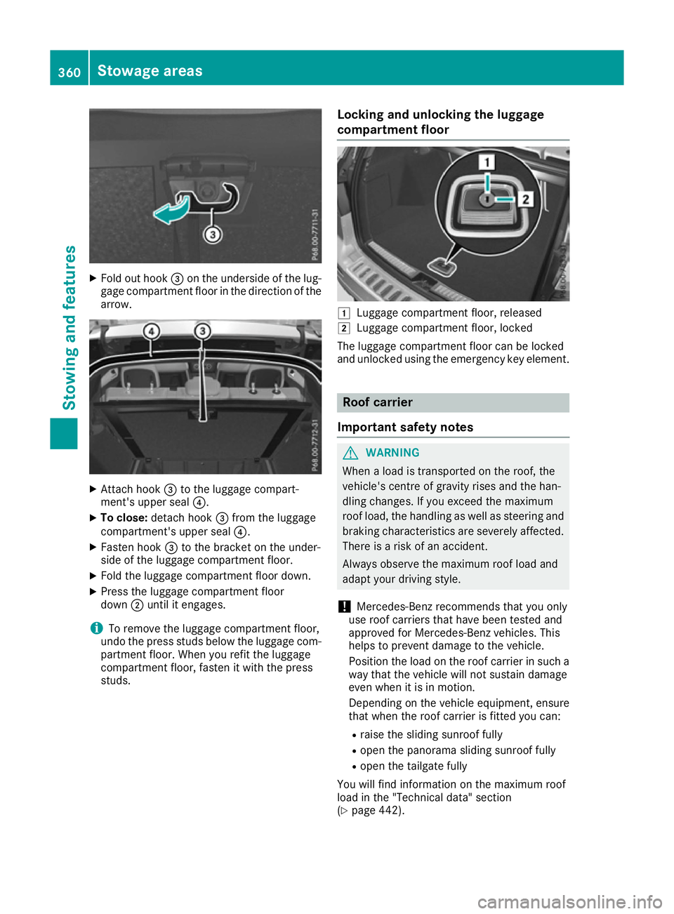
X
Fold out hook =on the underside of the lug-
gage compartment floor in the direction of the arrow. X
Attach hook =to the luggage compart-
ment's upper seal ?.
X To close: detach hook =from the luggage
compartment's upper seal ?.
X Fasten hook =to the bracket on the under-
side of the luggage compartment floor.
X Fold the luggage compartment floor down.
X Press the luggage compartment floor
down ;until it engages.
i To remove the luggage compartment floor,
undo the press studs below the luggage com-
partment floor. When you refit the luggage
compartment floor, fasten it with the press
studs. Locking and unlocking the luggage
compartment floor 1
Luggage compartment floor, released
2 Luggage compartment floor, locked
The luggage compartment floor can be locked
and unlocked using the emergency key element. Roof carrier
Important safety notes G
WARNING
When a load is transported on the roof, the
vehicle's centre of gravity rises and the han-
dling changes. If you exceed the maximum
roof load, the handling as well as steering and braking characteristics are severely affected.
There is a risk of an accident.
Always observe the maximum roof load and
adapt your driving style.
! Mercedes-Benz recommends that you only
use roof carriers that have been tested and
approved for Mercedes-Benz vehicles. This
helps to prevent damage to the vehicle.
Position the load on the roof carrier in such a way that the vehicle will not sustain damage
even when it is in motion.
Depending on the vehicle equipment, ensure
that when the roof carrier is fitted you can:
R raise the sliding sunroof fully
R open the panorama sliding sunroof fully
R open the tailgate fully
You will find information on the maximum roof
load in the "Technical data" section
(Y page 442). 360
Stowage areasStowing and features