2015 MERCEDES-BENZ GLE SUV tailgate
[x] Cancel search: tailgatePage 134 of 453
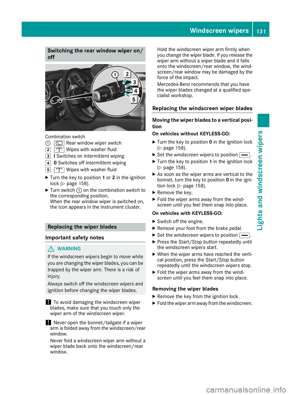
Switching the rear window wiper on/
off Combination switch
:
è Rear window wiper switch
2 b Wipes with washer fluid
3 ISwitches on intermittent wiping
4 0Switches off intermittent wiping
5 b Wipes with washer fluid
X Turn the key to position 1or 2in the ignition
lock (Y page 158).
X Turn switch :on the combination switch to
the corresponding position.
When the rear window wiper is switched on,
the icon appears in the instrument cluster. Replacing the wiper blades
Important safety notes G
WARNING
If the windscreen wipers begin to move while
you are changing the wiper blades, you can be trapped by the wiper arm. There is a risk of
injury.
Always switch off the windscreen wipers and
ignition before changing the wiper blades.
! To avoid damaging the windscreen wiper
blades, make sure that you touch only the
wiper arm of the windscreen wiper.
! Never open the bonnet/tailgate if a wiper
arm is folded away from the windscreen/rear
window.
Never fold a windscreen wiper arm without a
wiper blade back onto the windscreen/rear
window. Hold the windscreen wiper arm firmly when
you change the wiper blade. If you release the
wiper arm without a wiper blade and it falls
onto the windscreen/rear window, the wind-
screen/rear window may be damaged by the
force of the impact.
Mercedes-Benz recommends that you have
the wiper blades changed at a qualified spe-
cialist workshop.
Replacing the windscreen wiper blades Moving the wiper blades to a vertical posi-
tion
On vehicles without KEYLESS-GO:
X Turn the key to position 0in the ignition lock
(Y page 158).
X Set the windscreen wipers to position °.
X Turn the key to position 1in the ignition lock
(Y page 158).
X As soon as the wiper arms are vertical to the
bonnet, turn the key to position 0in the igni-
tion lock (Y page 158).
X Remove the key.
X Fold the wiper arms away from the wind-
screen until you feel them snap into place.
On vehicles with KEYLESS-GO:
X Switch off the engine.
X Remove your foot from the brake pedal.
X Set the windscreen wipers to position °.
X Press the Start/Stop button repeatedly until
the windscreen wipers start.
X When the wiper arms have reached the verti-
cal position, press the Start/Stop button
repeatedly until the windscreen wipers stop.
X Fold the wiper arms away from the wind-
screen until you feel them snap into place.
Removing the wiper blades X Remove the key from the ignition lock.
X Fold the wiper arm away from the windscreen. Windscreen wipers
131Lights and windscreen wipers Z
Page 203 of 453
The following driving systems are specially
adapted to off-road driving:
R the Offroad drive program (vehicles without
Off-Road Engineering package)
(Y page 254)
R Offroad andOffroad Plus drive programs
(vehicles with Off-Road Engineering pack-
age) . (Y page 254)
R LOW RANGE offroad gear (vehicles with the
Off-Road Engineering package)
(Y page 255)
R Differential lock (vehicles with the Off-Road
Engineering package) (Y page 255)
R Off-road ABS (Y page 71)
R Offroad 4ETS (Y page 76)
R Offroad ESP ®
(Y page 77)
R AIRMATIC package (vehicle level)
(Y page 220)
R DSR (Downhill Speed Regulation)
(Y page 252)
Observe the following notes:
R Stop the vehicle before driving off-road. If
necessary, select the offroad program
(Y page 254) or shift to the LOW RANGE off-
road gear (Y page 255).
R Select a vehicle level suitable for the off-road
terrain. To avoid damaging the vehicle, make sure there is always sufficient ground clear-
ance.
R Make sure that items of luggage and loads are
stowed safely and are well secured
(Y page 355).
R Always keep the engine running and in gear
when driving on a downhill gradient. Activate
DSR (Y page 252).
R Drive slowly and evenly, if necessary at walk-
ing pace.
R Ensure that the wheels are in contact with the
ground at all times.
R Drive with extreme care on unknown off-road
routes where visibility is poor. For safety rea-
sons, get out of the vehicle first and survey
the off-road route.
R Look out for obstacles such as rocks, holes,
tree stumps and furrows.
R Take care when turning on an uphill or down-
hill slope or when driving across a slope. The
vehicle could otherwise tip over. R
Always keep the doors, the tailgate and the
sliding sunroof closed while the vehicle is in
motion.
R Do not stray from marked routes or paths.
R Observe the notes on off-road fording
(Y page 198).
i Information about retrofitting special all-ter-
rain tyres is available from any qualified spe-
cialist workshop.
i Do not use the HOLD function when driving
off-road, on steep uphill or downhill gradients or on slippery or loose surfaces. The HOLD
function cannot hold the vehicle on such sur-faces.
Checklist before driving off-road X
Engine oil level: check the engine oil and top
it up if necessary.
When driving on steep gradients, the oil level must be sufficiently high to ensure a correct
oil supply in the vehicle.
X AdBlue ®
tank (BlueTEC vehicles): check
the level and top up if necessary
(Y page 180).
X Tyre-change tool kit: check that the jack is
working and make sure you have the wheel
wrench, a robust tow cable and a folding
spade in the vehicle.
X Wheels and tyres: check the tyre tread
depth and tyre pressure.
X Check for damage and remove any foreign
objects, e.g. small stones, from the wheels/
tyres.
X Replace any missing valve caps.
X Replace dented or damaged wheels.
X Wheels: dented or bent wheels can lead to a
loss of tyre pressure and damage to the tyre
bead. Before driving off-road, check the
wheels and replace them if necessary.
Checklist after driving off-road !
If you detect damage to the vehicle after
driving off-road, have the vehicle checked
immediately at a qualified specialist work-
shop.
Driving over rough terrain places greater
demands on your vehicle than driving on normal
roads. After driving off-road, check the vehicle.
This allows you to detect damage promptly and 200
Driving tipsDriving and parking
Page 236 of 453
See the notes on cleaning (Y
page 383).
For technical reasons, the flap may remain
open briefly after the reversing camera has
been deactivated.
Activating/deactivating the reversing
camera X
To activate: make sure that the key is in
position 2in the ignition lock.
X Make sure that the Activation by R gear
Activation by R gear
function is selected in the multimedia system; see the Digital Owner's Manual.
X Engage reverse gear.
The reversing camera flap opens. The multi-
media system shows the area behind the vehi-
cle with guide lines.
The image from the reversing camera is avail-
able throughout the manoeuvring process.
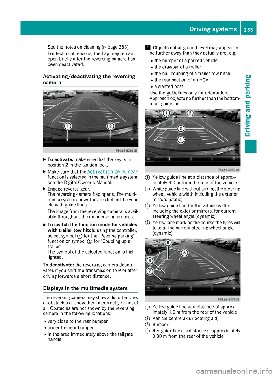
X To switch the function mode for vehicles
with trailer tow hitch: using the controller,
select symbol :for the "Reverse parking"
function or symbol ;for "Coupling up a
trailer".
The symbol of the selected function is high-
lighted.
To deactivate: the reversing camera deacti-
vates if you shift the transmission to Por after
driving forwards a short distance.
Displays in the multimedia system The reversing camera may show a distorted view
of obstacles or show them incorrectly or not at
all. Obstacles are not shown by the reversing
camera in the following locations:
R very close to the rear bumper
R under the rear bumper
R in the area immediately above the tailgate
handle !
Objects not at ground level may appear to
be further away than they actually are, e.g.:
R the bumper of a parked vehicle
R the drawbar of a trailer
R the ball coupling of a trailer tow hitch
R the rear section of an HGV
R a slanted post
Use the guidelines only for orientation.
Approach objects no further than the bottom- most guideline. :
Yellow guide line at a distance of approx-
imately 4.0 m fromthe rear of the vehicle
; White guide line without turning the steering
wheel, vehicle width including the exterior
mirrors (static)
= Yellow guide line for the vehicle width
including the exterior mirrors, for current
steering wheel angle (dynamic)
? Yellow lane marking the course the tyres will
take at the current steering wheel angle
(dynamic) A
Yellow guide line at a distance of approx-
imately 1.0 m fromthe rear of the vehicle
B Vehicle centre axis (locating aid)
C Bumper
D Red guide line at a distance of approximately
0.30 m from the rear of the vehicle Driving systems
233Driving and parking Z
Page 240 of 453
R
top view and image from the reversing cam-
era (130° viewing angle)
R top view and image from the front camera
(130° viewing angle without displaying the
maximum steering wheel angle)
R top view and enlarged rear view
R top view and enlarged front view
R top view and trailer view (vehicles with trailer
tow hitch)
R top view and rear-view images from the exte-
rior mirror cameras (rear wheel view)
R top view and forward-view images from the
exterior mirror cameras (front wheel view)
i The top view and trailer view are available
for vehicles equipped with a trailer tow hitch.
When the function is active and you shift the
transmission from Dor Rto N, the dynamic
guide lines are hidden.
When you change between transmission posi-
tions Dand R, you see the previously selected
front or rear view.
Distances measured by PARKTRONIC will also
be optically displayed:
R as red or yellow brackets around the vehicle
symbol in top view in split-screen mode or
R at the bottom right as red or yellow brackets
around the vehicle symbol in full-screen mode
The line thickness and colour of the brackets
show how far the vehicle is from an object.
R yellow brackets with thin lines: PARKTRONIC
is active
R yellow brackets with normal lines: an object is
present in close range of the vehicle
R red line: an object is present in the immediate
close range of the vehicle
i The camera in the rear area is protected
from raindrops and dust by means of a flap.
When the camera is activated, this flap opens.
The flap closes again when:
R you have finished the manoeuvring process
R you switch off the engine
R you open the luggage compartment
See the notes on cleaning (Y page 383).
For technical reasons, the flap may remain
open briefly after the camera has been deac-
tivated. Important safety notes The 360° camera is only an aid and may show a
distorted view of obstacles, show them incor-
rectly or not at all. The 360° camera is not a
substitute for attentive driving.
The responsibility for safe manoeuvring and
parking remains with you. Make sure that there
are no persons, animals or objects in range
while manoeuvring and parking.
You are always responsible for safety, and must always pay attention to your surroundings when
parking and manoeuvring. This applies to the
areas behind, in front of and beside the vehicle. You could otherwise endanger yourself and oth-
ers.
The 360° camera will not function or will func-
tion only in a limited manner:
R if the doors are open
R if the exterior mirrors are folded in
R if the tailgate is open
R in heavy rain, snow or fog
R at night or in very dark places
R if the cameras are exposed to very bright light
R if the area is lit by fluorescent bulbs or LED
lighting (the display may flicker)
R if there is a sudden change in temperature,
e.g. when driving into a heated garage in win-
ter
R if the camera lenses are dirty or covered
R if the vehicle components in which the cam-
eras are fitted are damaged. In this event,
have the camera position and setting checked
at a qualified specialist workshop.
Do not use the 360° camera under such cir-
cumstances. You could otherwise injure others
or damage objects when parking the vehicle.
Guide lines are always shown at road level. In
trailer mode, the guide lines are shown at the
level of the trailer coupling.
The field of vision and other functions of the
camera system may be restricted due to addi-
tional accessories on the rear of the vehicle (e.g.
licence plate holder, bicycle rack).
On vehicles with height-adjustable suspension,
due to the technical conditions, leaving the
standard height can result in:
R inaccuracies in the guide lines
R inaccuracies in the display of generated
images (top view) Driving systems
237Driving and parking Z
Page 241 of 453
Activation conditions
The 360° camera image can be displayed if:
R your vehicle is equipped with a 360° camera
R the key is in position 2in the ignition lock
R the multimedia system is switched on
Activating the 360° camera X
Press the Øbutton in the centre console
for longer than two seconds.
The following appears depending on whether transmission position Dor Ris selected:
R a split-screen with top view and the image
from the front camera or
R a split-screen with top view and the image
from the reversing camera
or X Press the Øbutton in the centre console.
The vehicle menu appears.
X Select 360°
360° camera camera and press 7to confirm.
The following appears depending on whether transmission position Dor Ris selected:
R a split-screen with top view and the image
from the front camera or
R a split-screen with top view and the image
from the reversing camera
Switching on the 360° camera using
reverse gear You can show images from the 360° camera
automatically by engaging reverse gear.
X Make sure that the key is in position 2in the
ignition lock.
X Make sure that the Activation by R gear
Activation by R gear
function is selected in the multimedia system (see the separate operating instructions).
X To show the 360° camera image: engage
reverse gear.
The multimedia system shows the area
behind the vehicle in split-screen mode. You
see the top view of the vehicle and the image from the reversing camera. Selecting the split-screens or 180° view Selecting split-screen view
X To switch to the line with the vehicle icons:
slide 5the controller.
X To select one of the vehicle icons: turn 3
the controller.
X To switch to 180° view 180° view:turn 3 the con-
troller to select 180° view
180° viewand press7to
confirm.
i The
180°
180° view
viewoption is only available in the
following views:
R Top view with image from the reversing
camera
R Top view with image from the front camera
Displays in the multimedia system Important safety notes
The camera system may show a distorted view
of obstacles or show them incorrectly or not at
all. Obstacles are not shown by the system in the
following locations:
R under the front and rear bumpers
R very close to the front and rear bumpers
R in the area immediately above the tailgate
handle
R very close to the exterior mirrors
R in the transitional areas between the various
cameras in the virtual top view
! Objects not at ground level may appear to
be further away than they actually are, e.g.:
R the bumper of a parked vehicle
R the drawbar of a trailer
R the ball coupling of a trailer tow hitch
R the rear section of an HGV
R a slanted post
Use the guidelines only for orientation.
Approach objects no further than the bottom- most guideline. 238
Driving systemsDriving and pa
rking
Page 275 of 453
Hybrid drive system
Problem
Possible causes/consequences and
M
MSolutions The hybrid drive system
has been switched off
automatically. You have been in an accident.
The hybrid drive system remains switched off if:
R the internal combustion engine cannot be restarted after a few
seconds.
R the red 6restraint system warning lamp in the instrument clus-
ter is lit.
X Consult a qualified specialist workshop. The hybrid drive system
has been switched off
automatically. The multi-
function display also
shows a display mes-
sage. An electrical short circuit has occurred in the hybrid drive system or an
electrical connection has been disconnected.
X Observe the additional display messages in the multifunction dis-
play (Y page 300).
X Consult a qualified specialist workshop. Towing a trailer
Important safety notes
G
WARNING
Vehicles with level control:
The vehicle level may be changed uninten-
tionally, e.g. by other persons. If this happens while you are coupling or decoupling a trailer,
you could become trapped. In addition, other
people could become trapped if their limbs
are between the vehicle body and the wheels or underneath the vehicle. There is a risk of
injury.
When coupling or decoupling a trailer, make
sure that no one:
R opens or closes the doors or the tailgate
R initiates a level change or turns the
DYNAMIC SELECT Controller
R locks or unlocks the vehicle G
WARNING
You could lose control of the vehicle/trailer
combination if it begins to swerve. The vehi-
cle/trailer combination could even overturn.
There is a risk of an accident.
On no account should you attempt to
straighten out the vehicle/trailer combina- tion by increasing speed. Decrease your
speed and do not countersteer. Brake if nec-
essary. G
WARNING
If the maximum permissible load for a carrier system is exceeded, the carrier could come
loose from the vehicle and endanger other
road users. There is a risk of an accident and injury.
Never exceed the maximum permissible load
when using a carrier.
Exceeding the maximum permissible nose-
weight of the trailer drawbar on the ball coupling
may cause damage to the following:
R your vehicle
R the trailer
R the ball coupling
R trailer tow hitch
The vehicle/trailer combination could become
unstable.
If the noseweight used is lower than the mini-
mum permissible noseweight, the vehicle/
trailer combination could also become unstable. 272
Towing a trailerDriving and parking
Page 277 of 453
When towing a trailer, your vehicle's handling
characteristics will be different in comparison to
when driving without a trailer and it will con-
sume more fuel.
Use the left-hand gearshift paddle to shift to a
lower gear on long and steep downhill gradients.
This also applies if you have activated cruise
control, SPEEDTRONIC or DISTRONIC PLUS.
This will use the braking effect of the engine, so
less braking will be required to maintain vehicle
speed. This relieves the load on the brake sys-
tem and prevents the brakes from overheating
and wearing too quickly. If you need additional
braking, depress the brake pedal repeatedly
rather than continuously.
Driving tips If the trailer swings from side to side:
X Do not accelerate.
X Do not countersteer.
X Brake if necessary.
R Maintain a greater distance to the vehicle in
front than when driving without a trailer.
R Avoid braking abruptly. If possible, brake gen-
tly at first to allow the trailer to run on. Then,
increase the braking force rapidly.
R The values given for gradient-climbing capa-
bilities from a standstill refer to sea level.
When driving in mountainous areas, note that
the power output of the engine, and conse-
quently the vehicle's gradient-climbing capa-
bility, decrease with increasing altitude. Swinging out the ball coupling
G
WARNING
If the ball coupling is not engaged, the trailer
may come loose. There is a risk of an accident.
Make sure that the ball coupling is securely
engaged and locked in position.
! Do not attempt to speed the up the swing-
out procedure by applying additional pressure
with your foot. The system could otherwise be
mechanically damaged. To fold out the ball coupling, you have two
options:
R use the switch in the driver's door (all vehicles
except PLUG-IN HYBRID vehicles)
R use the switch in the tailgate
The trailer power socket is integrated into the
ball coupling and swivels out with it.
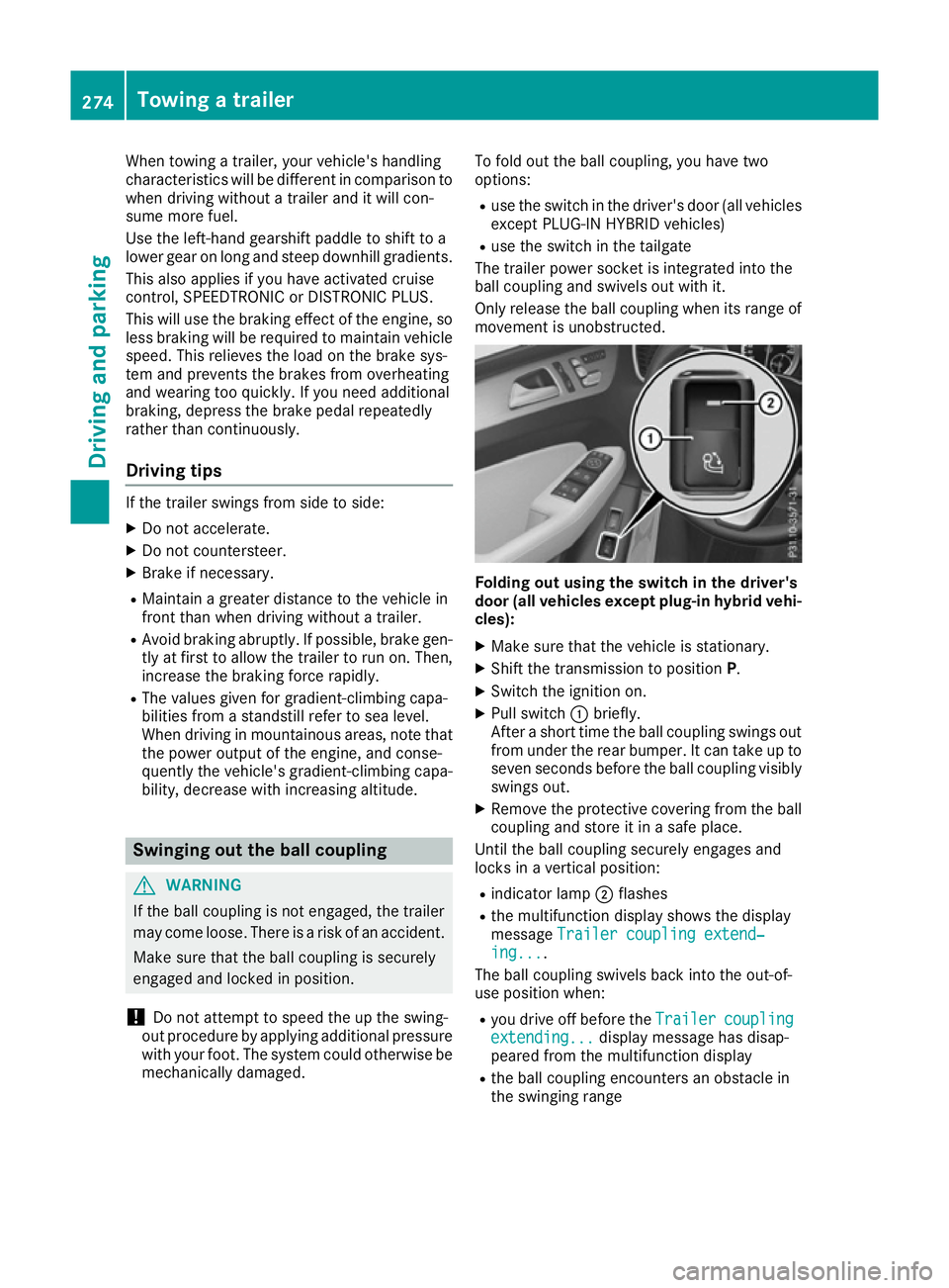
Only release the ball coupling when its range of movement is unobstructed. Folding out using the switch in the driver's
door (all vehicles except plug-in hybrid vehi-
cles):
X Make sure that the vehicle is stationary.
X Shift the transmission to position P.
X Switch the ignition on.
X Pull switch :briefly.
After a short time the ball coupling swings out from under the rear bumper. It can take up to
seven seconds before the ball coupling visibly
swings out.
X Remove the protective covering from the ball
coupling and store it in a safe place.
Until the ball coupling securely engages and
locks in a vertical position:
R indicator lamp ;flashes
R the multifunction display shows the display
message Trailer coupling extend‐ Trailer coupling extend‐
ing...
ing....
The ball coupling swivels back into the out-of-
use position when:
R you drive off before the Trailer
Trailercoupling
coupling
extending...
extending... display message has disap-
peared from the multifunction display
R the ball coupling encounters an obstacle in
the swinging range 274
Towing a trailerDriving and parking
Page 278 of 453
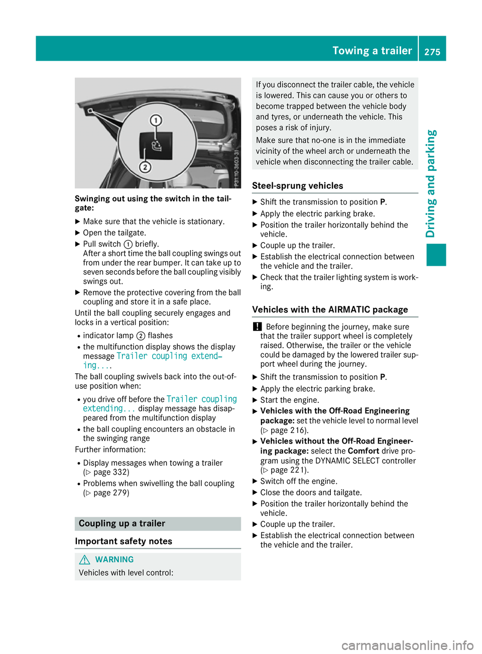
Swinging out using the switch in the tail-
gate:
X Make sure that the vehicle is stationary.
X Open the tailgate.
X Pull switch :briefly.
After a short time the ball coupling swings out from under the rear bumper. It can take up to
seven seconds before the ball coupling visibly
swings out.
X Remove the protective covering from the ball
coupling and store it in a safe place.
Until the ball coupling securely engages and
locks in a vertical position:
R indicator lamp ;flashes
R the multifunction display shows the display
message Trailer coupling extend‐ Trailer coupling extend‐
ing...
ing....
The ball coupling swivels back into the out-of-
use position when:
R you drive off before the Trailer Trailercoupling
coupling
extending...
extending... display message has disap-
peared from the multifunction display
R the ball coupling encounters an obstacle in
the swinging range
Further information:
R Display messages when towing a trailer
(Y page 332)
R Problems when swivelling the ball coupling
(Y page 279) Coupling up a trailer
Important safety notes G
WARNING
Vehicles with level control: If you disconnect the trailer cable, the vehicle
is lowered. This can cause you or others to
become trapped between the vehicle body
and tyres, or underneath the vehicle. This
poses a risk of injury.
Make sure that no-one is in the immediate
vicinity of the wheel arch or underneath the
vehicle when disconnecting the trailer cable.
Steel-sprung vehicles X
Shift the transmission to position P.
X Apply the electric parking brake.
X Position the trailer horizontally behind the
vehicle.
X Couple up the trailer.
X Establish the electrical connection between
the vehicle and the trailer.
X Check that the trailer lighting system is work-
ing.
Vehicles with the AIRMATIC package !
Before beginning the journey, make sure
that the trailer support wheel is completely
raised. Otherwise, the trailer or the vehicle
could be damaged by the lowered trailer sup- port wheel during the journey.
X Shift the transmission to position P.
X Apply the electric parking brake.
X Start the engine.
X Vehicles with the Off-Road Engineering
package:
set the vehicle level to normal level
(Y page 216).
X Vehicles without the Off-Road Engineer-
ing package:
select theComfortdrive pro-
gram using the DYNAMIC SELECT controller
(Y page 221).
X Switch off the engine.
X Close the doors and tailgate.
X Position the trailer horizontally behind the
vehicle.
X Couple up the trailer.
X Establish the electrical connection between
the vehicle and the trailer. Towing a trailer
275Driving and parking Z