2015 MERCEDES-BENZ GLE SUV climate control
[x] Cancel search: climate controlPage 152 of 453
Setting the departure time
You can set the departure time using the on-
board computer or via the Mercedes connect
me web App. The activation of the "Pre-entry
climate control at departure time" function can
be linked to this departure time. Your vehicle will then be cooled or heated until the desired tem-perature is reached in time for the set departure
time. "Pre-entry climate control at departure
time" will be activated a maximum of 55 minutes before departure. If the departure is delayed,
the vehicle will be heated or cooled for a further five minutes.
X To set the departure time: set the departure
time using the on-board computer
(Y page 292). Set the departure time using
the Mercedes connect me web App: http://
www.mercedes.me.
X To activate or deactivate "Pre-entry cli-
mate control at departure time": activate
or deactivate "Pre-entry climate control at
departure time" using the on-board com-
puter. Activate or deactivate "Pre-entry cli-
mate control at departure time" using the
Mercedes connect me web App: http://
www.mercedes.me.
The "Pre-entry climate control at departure
time" function is automatically deactivated
when the vehicle is started. The following func-
tions remain active:
R Seat heating
R Seat ventilation
R Ionisation
To deactivate "Pre-entry climate control at
departure time": the activated "Pre-entry cli-
mate control at departure time" can be deacti-
vated using the button (Y page 149).
Activating/deactivating "Immediate
pre-entry climate control" via the but-
ton You can activate "Immediate pre-entry climate
control" even if the vehicle interior is already at
the desired temperature. This means, for exam- ple, that the vehicle interior continues to be
cooled or heated if the journey is interrupted for
up to 50 minutes and the interior temperature is kept constant. X
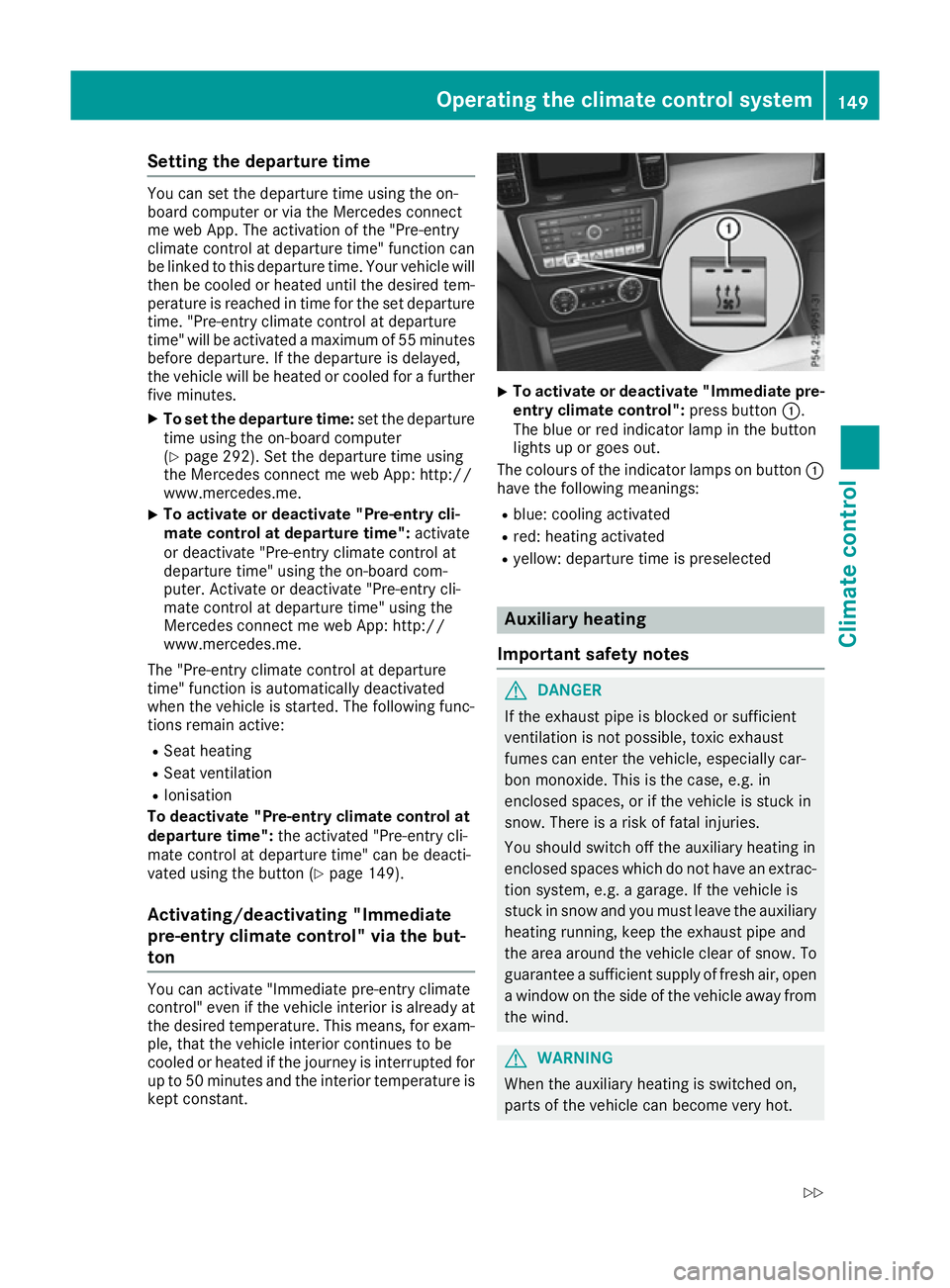
To activate or deactivate "Immediate pre-
entry climate control": press button:.
The blue or red indicator lamp in the button
lights up or goes out.
The colours of the indicator lamps on button :
have the following meanings:
R blue: cooling activated
R red: heating activated
R yellow: departure time is preselected Auxiliary heating
Important safety notes G
DANGER
If the exhaust pipe is blocked or sufficient
ventilation is not possible, toxic exhaust
fumes can enter the vehicle, especially car-
bon monoxide. This is the case, e.g. in
enclosed spaces, or if the vehicle is stuck in
snow. There is a risk of fatal injuries.
You should switch off the auxiliary heating in
enclosed spaces which do not have an extrac- tion system, e.g. a garage. If the vehicle is
stuck in snow and you must leave the auxiliary
heating running, keep the exhaust pipe and
the area around the vehicle clear of snow. To guarantee a sufficient supply of fresh air, open
a window on the side of the vehicle away from the wind. G
WARNING
When the auxiliary heating is switched on,
parts of the vehicle can become very hot. Operating the climate control system
149Climate control
Z
Page 153 of 453

Flammable materials such as leaves, grass or
twigs may ignite if they come into contact
with:
R hot parts of the exhaust system
R the exhaust gas itself
There is a risk of fire.
When the auxiliary heating is switched on,
make sure that:
R no flammable materials come into contact
with hot vehicle components
R the exhaust gas can escape from the
exhaust pipe unhindered
R the exhaust gas does not come into contact
with flammable materials.
The auxiliary heating is fitted under the front
wing on the left-hand side of the vehicle. The
emissions outlet is found behind the left front
wheel. ! Operating the auxiliary heating/ventilation
draws on the vehicle battery. After you have
heated or ventilated the vehicle a maximum of two times, drive for a longer distance.
Switch the auxiliary heating on regularly once a month for about ten minutes.
The auxiliary heating heats the air in the vehicle
interior to the set temperature. This occurs with- out using the heat of the running engine. The
auxiliary heating is operated directly using the
vehicle's fuel. For this reason, the tank content
must be at least at reserve fuel level to ensure
that the auxiliary heating functions.
The auxiliary heating or auxiliary ventilation
automatically adjusts to changes in tempera-
ture and weather conditions. For this reason,
the auxiliary heating could switch from ventila-
tion mode to heating mode or from heating
mode to ventilation mode.
The auxiliary heating switches off when the
engine is switched off. The auxiliary ventilation
switches off when you turn the key to position 2
(Y page 158).
The auxiliary heating switches off automatically after 50 minutes. This time limit can be altered.
To do this, visit a qualified specialist workshop.
You cannot use the auxiliary ventilation to cool
the vehicle interior to a temperature lower than
the outside temperature. Before switching on X
Turn the key to position 2in the ignition lock
(Y page 158).
X Set the desired temperature.
The auxiliary heating/ventilation can be activa-
ted even when climate control is set to manual.
Optimum comfort can be attained when the sys-
tem is set to automatic mode. Set the temper-
ature to 22 †.
The auxiliary heating or auxiliary ventilation can
be switched on/off using the button on the
centre console or the remote control.
The on-board computer can be used to specify
up to three departure times, one of which may
be preselected (Y page 295).
Switching the auxiliary heating/venti-
lation on or off using the button on the
centre console General notes
The colours of the indicator lamps in button
:
mean the following:
R blue: auxiliary ventilation is switched on
R red: auxiliary heating is activated
R yellow: departure time is preselected
(Y page 295).
Switching on/off X To switch on the auxiliary heating or aux-
iliary ventilation:
press button:.
The red or blue indicator lamp in button :
lights up.
X To switch off the auxiliary heating or aux-
iliary ventilation: press button:.
The red or blue indicator lamp in button :
goes out. 150
Operating the climate control systemClimate control
Page 154 of 453

Switching the auxiliary heating/venti-
lation on or off using the remote control
General notes
Your vehicle comes with one remote control.
You may use two additional remote controls for
your vehicle. For more information, please con-
tact a qualified specialist workshop.
Store the remote control for the auxiliary heat-
ing so that the auxiliary heating cannot be
switched on unintentionally. In particular,
ensure that the remote control for the auxiliary
heating is kept out of the reach of children.
The remote control has a range of approximately
300 metres. This range is reduced by:
R sources of radio interference
R solid objects between the remote control and
the vehicle
R the remote control being in an unfavourable
position in relation to the vehicle
R transmitting from an enclosed space
If the remote control battery is low, the battery
symbol on the left of the display is shown as
empty. Replace the remote control battery and
observe the important safety notes when doing so (Y page 152).
Activating and deactivating the auxiliary
heating or auxiliary ventilation Remote control
:
Display
; u Activates the auxiliary heating or aux-
iliary ventilation
Checks the status
= . Sets the departure time
? ^ Deactivates the auxiliary heating or
auxiliary ventilation
A , Sets the departure time X
To activate: press and hold the ubutton.
ON is shown in the remote control display.
X To deactivate: press and hold the ^but-
ton.
OFF is shown in the remote control display.
Checking the status of the auxiliary heat-
ing or auxiliary ventilation
X Briefly press the ubutton.
The following messages may appear in the dis-
play: Display Meaning
The auxiliary heating or
auxiliary ventilation is
switched off.
The auxiliary ventilation is
switched on. The number
in the display shows the
remaining time (in
minutes) for the auxiliary
ventilation.
The auxiliary heating is
switched on. The number
in the display shows the
remaining time (in
minutes) for the auxiliary
heating.
A departure time has been
activated. The departure
time appears in the dis-
play. Operating the climate control system
151Climate control Z
Page 155 of 453
 for the auxiliary
ventilation. If the vehicle is")
A departure time has been
activated. The auxiliary
ventilation is currently
activated. The number in
the display shows the
remaining time (in
minutes) for the auxiliary
ventilation. If the vehicle is
not started after this time, the running time is
increased by five minutes. A departure time has been
activated. The auxiliary
heating is currently activa-
ted. The number in the dis- play shows the remaining
time (in minutes) for the
auxiliary heating. If the
vehicle is not started after
this time, the running time is increased by five
minutes. If the engine has not yet reached operating tem-
perature when it is started, the auxiliary heating running time is increased. The auxiliary heating
continues to run until the operating temperature
is reached. If this is the case, the ysymbol
appears in the remote control display and the
running time is zero minutes.
Setting the departure time
Make sure that the time set in the vehicle is
correct before setting the departure time (see
the separate operating instructions). Otherwise, the auxiliary heating may switch on at the wrong
time and at an unsuitable location. When setting the departure time, also observe the important
safety notes (Y page 149).
X Briefly press the ubutton.
X Press the ,or. button repeatedly
until the time to be changed appears in the
display.
X Press the uand^ buttons simultane-
ously.
The Îsymbol in the remote control display
flashes.
X Press the ,or. button to set the
desired departure time. i
The longer you press the
,or. but-
ton, the faster the time changes.
X Press the uand^ buttons simultane-
ously.
The new departure time is stored.
Activating the set departure time
X Briefly press the ubutton.
X Press the ,or. button repeatedly
until the desired departure time appears in
the display.
X Press the ubutton.
The Ísymbol, the departure time and,
depending on the selected departure time,
the letter A, BorCappear in the display.
Deactivating the set departure time
X Briefly press the ubutton.
The status of the auxiliary heating is shown in the display.
X Press the .button.
The first departure time stored appears in the
display.
X Press the ^button.
OFF is shown in the remote control display.
Replacing the remote control battery Important safety notes
G
WARNING
Batteries contain toxic and corrosive substan- ces. If batteries are swallowed, it can result in
severe health problems. There is a risk of fatal injury.
Keep batteries out of the reach of children. If
a battery is swallowed, seek medical attention immediately. H
Environmental note Batteries contain pollutants.
It is illegal to dispose of them
with the household rubbish.
They must be collected sep-
arately and disposed of in an 152
Operating the climate control systemClimate control
Page 156 of 453

environmentally responsible
recycling system. Dispose of batteries in an
environmentally responsible
manner. Take discharged
batteries to a qualified spe-
cialist workshop or to a col-
lection point for used batter-
ies.
Replacing the battery If the battery needs to be replaced, the battery
symbol on the left of the display is shown as
empty. A CR2450 lithium battery is required
when replacing the battery.
X Press a pointed object into recess :.
X Slide battery cover ;backwards in the direc-
tion of the arrow.
X Remove old battery =.
X Insert the new battery with the lettering
facing upwards.
X Slide battery cover ;in the opposite direc-
tion to the arrow on the remote control until it
engages.
X Use the remote control to check the vehicle's
auxiliary heating functions. Operating the climate control system
153Climate control Z
Page 157 of 453

Problems with the auxiliary heating/ventilation
Problem
Possible causes/consequences and
M
MSolutions FAIL¨ The signal transmission between the transmitter and the vehicle is
faulty.
X
Change your position in relation to the vehicle, moving closer if
necessary.
X Make another attempt to switch the auxiliary heating or auxiliary
ventilation on or off using the remote control. FAIL The auxiliary heating/ventilation cannot be switched on or has
switched itself off.
The starter battery is not sufficiently charged.
X Charge the starter battery.
X Make another attempt to switch on the auxiliary heating/ventilation
using the remote control. The auxiliary heating cannot be switched on or has switched itself off.
The fuel tank content is below the reserve fuel level.
X Refuel at the nearest filling station.
X Make another attempt to switch on the auxiliary heating/ventilation
using the remote control. The auxiliary heating/ventilation cannot be switched on or has
switched itself off.
The auxiliary heating/ventilation is malfunctioning.
X Have the auxiliary heating/ventilation checked at a qualified spe-
cialist workshop. Adjusting the air vents
Important safety notes
G
WARNING
Very hot or very cold air can flow from the air vents. This could result in burns or frostbite in the immediate vicinity of the air vents. There
is a risk of injury.
Make sure that all vehicle occupants always
maintain a sufficient distance to the air out-
lets. If necessary, redirect the airflow to
another area of the vehicle interior.
In order to ensure the direct flow of fresh air
through the air vents into the vehicle interior,
please observe the following notes:
R keep the air inlet grille on the bonnet and in
the engine compartment on the front- passenger side free of blockages, such as ice,
snow or leaves.
R never cover the vents or ventilation grilles in
the vehicle interior
i For virtually draught-free ventilation, adjust
the sliders of the air vents to the centre posi- tion. 154
Adjusting the air ventsClimate control
Page 158 of 453

Adjusting the centre air vents
:
Centre air vent, left
; Centre air vent, right
= Centre vent thumbwheel, right
? Centre vent thumbwheel, left
X To open or close: turn thumbwheels=
and ?to the left or right. Adjusting the side air vents
:
Side window demister vent
; Side air vent
= Thumbwheel for side air vent
X To open or close: turn thumbwheel=up or
down. Adjusting the glove compartment air
vent
! Close the air vent when heating the vehicle.
At high outside temperatures, open the air
vent and activate the "cooling with air dehu-
midification" function. Otherwise, tempera-
ture-sensitive items stored in the glove com-
partment could be damaged. :
Air vent thumbwheel
; Air vent
When automatic climate control is activated, the
glove compartment can be ventilated, for
instance to cool its contents. The level of airflow depends on the airflow and air distribution set-
tings.
X To open or close: turn thumbwheel:to the
right or left. Setting the rear-compartment air
vents
Adjusting the centre air vents in the
rear compartment Example: centre vents with rear control panel
:
Rear-compartment air vent thumbwheel
; Rear-compartment air vent, right
= Rear control panel
? Rear-compartment air vent, left
X To open or close: turn thumbwheel:up or
down. Adjusting the air vents
155Climate control Z
Page 187 of 453

the energy needed to operate the electric motor
and releases it again.
The electric motor uses energy that has been
stored in the high-voltage battery when pulling
away, accelerating and during the journey.
In overrun mode, kinetic energy is converted by
means of energy recuperation into electrical
energy and stored in the high-voltage battery.
Information on overrun mode (Y page 269).
The high-voltage battery can be charged as fol-
lows:
R through energy recuperation while the vehicle
is in motion
R during the journey by the combustion engine
in CHARGE operating mode (Y page 262)
R with the relevant charging cable at a mains
socket while the vehicle is stationary
R with the relevant charging cable at a wallbox
while the vehicle is stationary
R with the relevant charging cable at a charging
station while the vehicle is stationary
The high-voltage battery can be charged in a
nominal voltage range from 100 Vto 240 V.
You can view the charge status of the high-volt-
age battery in the multifunction display. You can
find information in "PLUG-IN HYBRID opera-
tion", section "Menus and submenus" under
"Energy flow display" (Y page 263).
High and low outside temperatures Low outside temperatures
The maximum performance of the high-voltage
battery is significantly reduced at very low out-
side temperatures. The high-voltage battery is
then no longer able to provide the normal elec-
trical power output.
High outside temperatures
To prevent damage to the high-voltage battery
due to very high outside temperatures, the max- imum power output of the high-voltage battery
is reduced by the vehicle.
Energy consumption and electrical
range The maximum electrical range is generally
reduced by:
R high and low outside temperatures
R operating the climate control system
R switching on consumers The battery's physical characteristics are such,
that leaving the vehicle parked for long periods
at low outdoor temperatures without charging it
can lead to:
R a reduction in battery performance
R longer charge times
Notes on battery care Avoid storing or transporting the vehicle at
excessively high or low temperatures over a long
period.
If you park the vehicle and leave it stationary for
long periods:
R check the charge status of the high-voltage
battery more often
R connect the vehicle to a power supply.
This prevents self-discharge and damage to the
high-voltage battery.
Terms of use Please note the information on exceptions and
limitations in the warranty documentation and
in the Service Booklet.
Handling the charging cable and charg- ing cable controls Do not leave the charging cable controls
(Y
page 185) hanging loose from a mains
socket. Otherwise, this could result in a poor
contact with the mains socket and malfunctions
when charging the vehicle.
To ensure that the brackets within the charging
cable controls are not subjected to incorrect
loads, observe the following:
R never lift or carry the controls by the charging
cable connector or the mains plug
R to transport the charging cable, the charging
cable can be:
- charging cable variant 1: wrapped around
the controls or secured to the control hous-
ing.
- charging cable variant 2: wrapped around
the controls and secured with a strap
Information on charging cable variants can be
found under "Charging cable for mains sockets"
(Y page 185). 184
Charging the high-voltage batteryDriving and parking