2015 MERCEDES-BENZ GLE SUV height
[x] Cancel search: heightPage 240 of 453
R
top view and image from the reversing cam-
era (130° viewing angle)
R top view and image from the front camera
(130° viewing angle without displaying the
maximum steering wheel angle)
R top view and enlarged rear view
R top view and enlarged front view
R top view and trailer view (vehicles with trailer
tow hitch)
R top view and rear-view images from the exte-
rior mirror cameras (rear wheel view)
R top view and forward-view images from the
exterior mirror cameras (front wheel view)
i The top view and trailer view are available
for vehicles equipped with a trailer tow hitch.
When the function is active and you shift the
transmission from Dor Rto N, the dynamic
guide lines are hidden.
When you change between transmission posi-
tions Dand R, you see the previously selected
front or rear view.
Distances measured by PARKTRONIC will also
be optically displayed:
R as red or yellow brackets around the vehicle
symbol in top view in split-screen mode or
R at the bottom right as red or yellow brackets
around the vehicle symbol in full-screen mode
The line thickness and colour of the brackets
show how far the vehicle is from an object.
R yellow brackets with thin lines: PARKTRONIC
is active
R yellow brackets with normal lines: an object is
present in close range of the vehicle
R red line: an object is present in the immediate
close range of the vehicle
i The camera in the rear area is protected
from raindrops and dust by means of a flap.
When the camera is activated, this flap opens.
The flap closes again when:
R you have finished the manoeuvring process
R you switch off the engine
R you open the luggage compartment
See the notes on cleaning (Y page 383).
For technical reasons, the flap may remain
open briefly after the camera has been deac-
tivated. Important safety notes The 360° camera is only an aid and may show a
distorted view of obstacles, show them incor-
rectly or not at all. The 360° camera is not a
substitute for attentive driving.
The responsibility for safe manoeuvring and
parking remains with you. Make sure that there
are no persons, animals or objects in range
while manoeuvring and parking.
You are always responsible for safety, and must always pay attention to your surroundings when
parking and manoeuvring. This applies to the
areas behind, in front of and beside the vehicle. You could otherwise endanger yourself and oth-
ers.
The 360° camera will not function or will func-
tion only in a limited manner:
R if the doors are open
R if the exterior mirrors are folded in
R if the tailgate is open
R in heavy rain, snow or fog
R at night or in very dark places
R if the cameras are exposed to very bright light
R if the area is lit by fluorescent bulbs or LED
lighting (the display may flicker)
R if there is a sudden change in temperature,
e.g. when driving into a heated garage in win-
ter
R if the camera lenses are dirty or covered
R if the vehicle components in which the cam-
eras are fitted are damaged. In this event,
have the camera position and setting checked
at a qualified specialist workshop.
Do not use the 360° camera under such cir-
cumstances. You could otherwise injure others
or damage objects when parking the vehicle.
Guide lines are always shown at road level. In
trailer mode, the guide lines are shown at the
level of the trailer coupling.
The field of vision and other functions of the
camera system may be restricted due to addi-
tional accessories on the rear of the vehicle (e.g.
licence plate holder, bicycle rack).
On vehicles with height-adjustable suspension,
due to the technical conditions, leaving the
standard height can result in:
R inaccuracies in the guide lines
R inaccuracies in the display of generated
images (top view) Driving systems
237Driving and parking Z
Page 276 of 453
To avoid hazardous situations:
R make sure to check the noseweight before
each journey
R use a drawbar noseweight as close as possi-
ble to the maximum noseweight
R do not exceed the maximum permissible
noseweight
R do not use a noseweight lower than the min-
imum noseweight
When reversing the vehicle towards the trailer,
make sure there is nobody between the trailer
and the vehicle.
Couple and uncouple the trailer carefully. If you do not couple the trailer to the towing vehicle
correctly, the trailer could become detached.
Make sure that the following values are not
exceeded:
R the permissible trailer drawbar noseweight
R the permissible trailer load
R the permissible rear axle load of the towing
vehicle
R the maximum permissible gross vehicle
weight of both the towing vehicle and the
trailer
The applicable permissible values, which must
not be exceeded, can be found:
R in your vehicle documents
R on the identification plates of the trailer tow
hitch and the trailer
R on the vehicle identification plate
If the values differ, the lowest value applies.
You will find the values approved by the manu-
facturer on the vehicle identification plates and
those for the towing vehicle under "Technical
data" (Y page 447).
When towing a trailer, your vehicle's handling
characteristics will be different in comparison to
when driving without a trailer.
The vehicle/trailer combination:
R is heavier
R is restricted in its acceleration and gradient-
climbing capability
R has an increased braking distance
R is affected more by strong crosswinds
R demands more sensitive steering
R has a larger turning circle
This can impair the vehicle's handling charac-
teristics. Adapt your driving style accordingly.
Maintain a safe distance. Drive carefully. When towing a trailer, always adjust your speed
to the current road and weather conditions. Do
not exceed the maximum permissible speed for
your vehicle/trailer combination. Notes on towing a trailer
General notes Check the tyre pressures when towing a trailer.
You will find the values in the tyre pressure table in the vehicle fuel filler flap (Y page 408).
Please note that when towing a trailer, the fol-
lowing driving systems have limited availability
or are not available at all.
R PARKTRONIC (Y page 225)
R Blind Spot Assist (Y page 244)
R Active Lane Keeping Assist (Y page 250)
R Active Parking Assist (Y page 228)
On vehicles without level control, the height of
the ball coupling will alter according to the load
placed on the vehicle. If necessary, use a trailer with a height-adjustable drawbar.
You will find fitting dimensions and loads under
"Technical data" (Y page 446).
Driving tips Observe the information on ESP
®
trailer stabili-
sation (Y page 77) and on pulling away with a
trailer (Y page 161).
Select the Comfortdrive program using the
DYNAMIC SELECT controller (Y page 166).
The maximum permissible speed for vehicle/
trailer combinations depends on the type of
trailer. Before beginning the journey, check the
trailer's documents to see what the maximum
permitted speed is. Observe the legally prescri-
bed maximum speed in the relevant country.
For certain Mercedes-Benz vehicles, the maxi-
mum permissible rear axle load is increased
when towing a trailer. See the "Technical data"
section to find out whether this applies to your
vehicle (Y page 447). If you utilise any of the
added maximum rear axle load when towing a
trailer, the vehicle/trailer combination may not
exceed a maximum speed of 100 km/hf or rea-
sons concerning the operating permit. This also
applies in countries in which the permissible
maximum speed for vehicle/trailer combina-
tions is above 100 km/h. Towing a trailer
273Driving and parking Z
Page 377 of 453
approximately 100 mm. The active bonnet is
triggered by pyrotechnics.
For the drive to the workshop, reset the trig-
gered active bonnet yourself. After being reset,
the active bonnet rests in the area of the hinges on the seals, and the hinges do not engage. For
this reason, we recommend that you do not
exceed a maximum permissible speed of
130 km/h on the way to the workshop. If the
active bonnet has been triggered, pedestrian
protection may be limited.
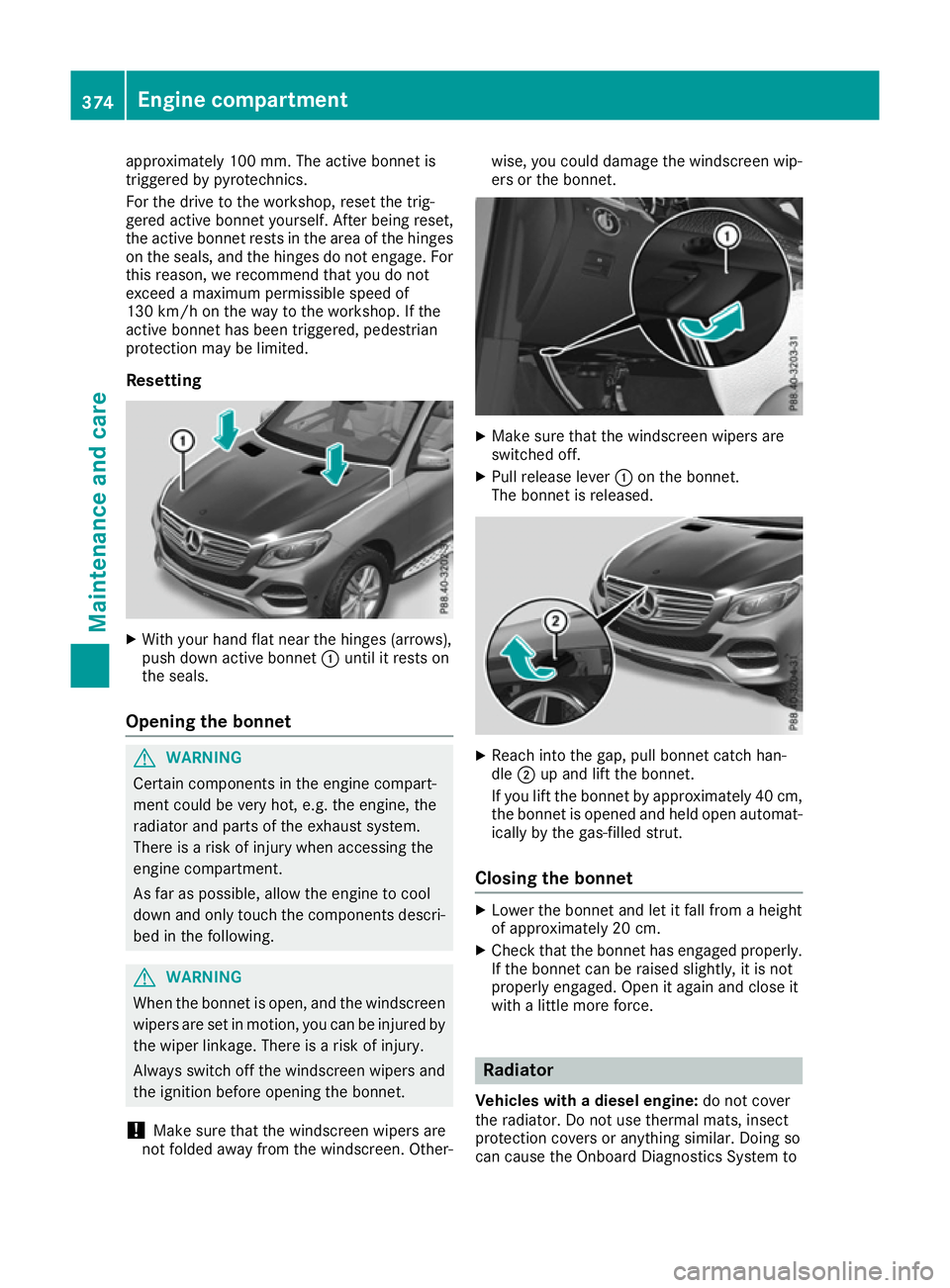
Resetting X
With your hand flat near the hinges (arrows),
push down active bonnet :until it rests on
the seals.
Opening the bonnet G
WARNING
Certain components in the engine compart-
ment could be very hot, e.g. the engine, the
radiator and parts of the exhaust system.
There is a risk of injury when accessing the
engine compartment.
As far as possible, allow the engine to cool
down and only touch the components descri- bed in the following. G
WARNING
When the bonnet is open, and the windscreen wipers are set in motion, you can be injured by
the wiper linkage. There is a risk of injury.
Always switch off the windscreen wipers and
the ignition before opening the bonnet.
! Make sure that the windscreen wipers are
not folded away from the windscreen. Other- wise, you could damage the windscreen wip-
ers or the bonnet.
X
Make sure that the windscreen wipers are
switched off.
X Pull release lever :on the bonnet.
The bonnet is released. X
Reach into the gap, pull bonnet catch han-
dle ;up and lift the bonnet.
If you lift the bonnet by approximately 40 cm, the bonnet is opened and held open automat-
ically by the gas-filled strut.
Closing the bonnet X
Lower the bonnet and let it fall from a height
of approximately 20 cm.
X Check that the bonnet has engaged properly.
If the bonnet can be raised slightly, it is not
properly engaged. Open it again and close it
with a little more force. Radiator
Vehicles with a diesel engine: do not cover
the radiator. Do not use thermal mats, insect
protection covers or anything similar. Doing so
can cause the Onboard Diagnostics System to 374
Engine compartmentMaintenance and care
Page 418 of 453
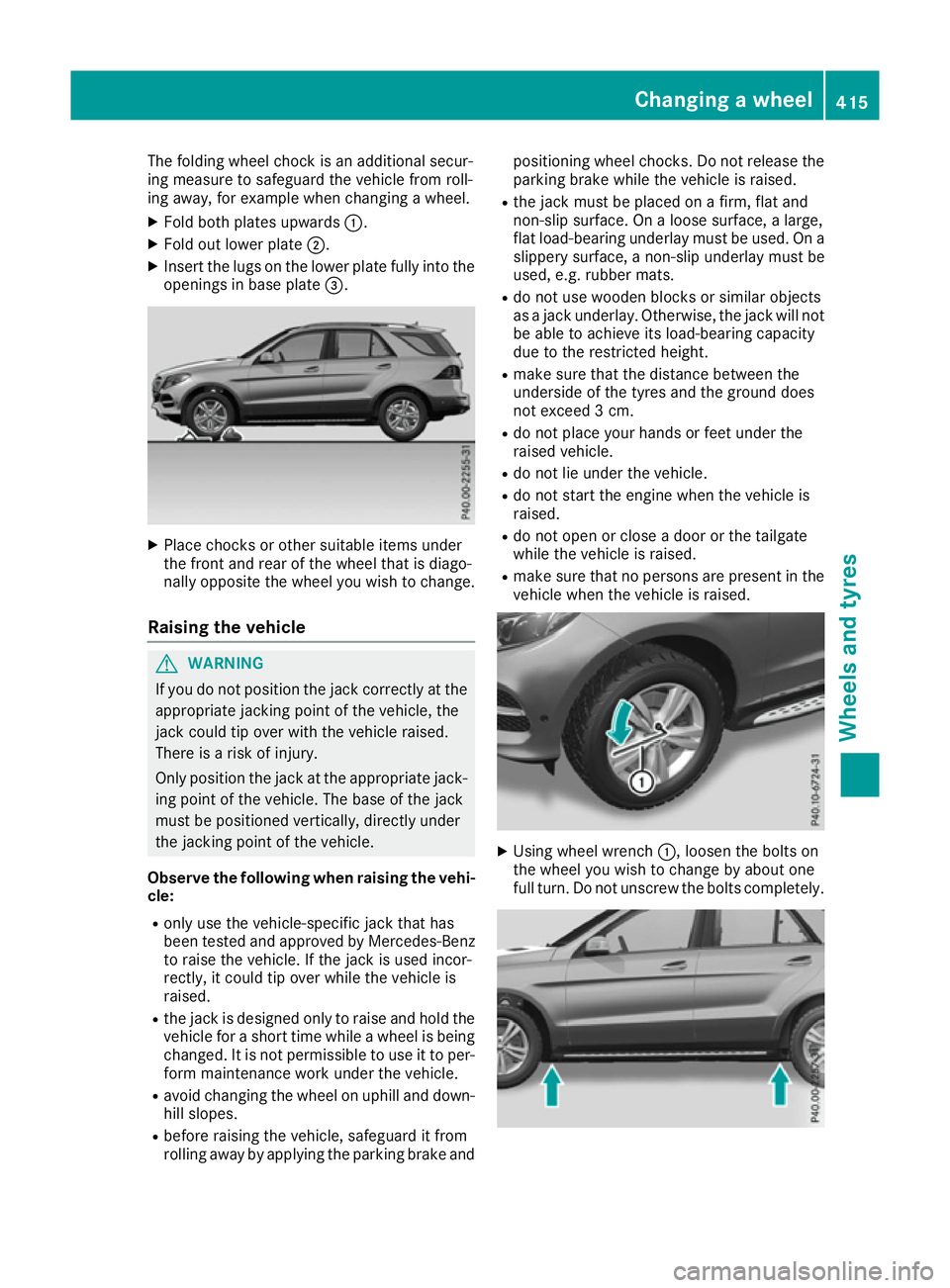
The folding wheel chock is an additional secur-
ing measure to safeguard the vehicle from roll-
ing away, for example when changing a wheel.
X Fold both plates upwards :.
X Fold out lower plate ;.
X Insert the lugs on the lower plate fully into the
openings in base plate =.X
Place chocks or other suitable items under
the front and rear of the wheel that is diago-
nally opposite the wheel you wish to change.
Raising the vehicle G
WARNING
If you do not position the jack correctly at the appropriate jacking point of the vehicle, the
jack could tip over with the vehicle raised.
There is a risk of injury.
Only position the jack at the appropriate jack-
ing point of the vehicle. The base of the jack
must be positioned vertically, directly under
the jacking point of the vehicle.
Observe the following when raising the vehi- cle:
R only use the vehicle-specific jack that has
been tested and approved by Mercedes-Benz
to raise the vehicle. If the jack is used incor-
rectly, it could tip over while the vehicle is
raised.
R the jack is designed only to raise and hold the
vehicle for a short time while a wheel is being
changed. It is not permissible to use it to per- form maintenance work under the vehicle.
R avoid changing the wheel on uphill and down-
hill slopes.
R before raising the vehicle, safeguard it from
rolling away by applying the parking brake and positioning wheel chocks. Do not release the
parking brake while the vehicle is raised.
R the jack must be placed on a firm, flat and
non-slip surface. On a loose surface, a large,
flat load-bearing underlay must be used. On a
slippery surface, a non-slip underlay must be
used, e.g. rubber mats.
R do not use wooden blocks or similar objects
as a jack underlay. Otherwise, the jack will not
be able to achieve its load-bearing capacity
due to the restricted height.
R make sure that the distance between the
underside of the tyres and the ground does
not exceed 3 cm.
R do not place your hands or feet under the
raised vehicle.
R do not lie under the vehicle.
R do not start the engine when the vehicle is
raised.
R do not open or close a door or the tailgate
while the vehicle is raised.
R make sure that no persons are present in the
vehicle when the vehicle is raised. X
Using wheel wrench :, loosen the bolts on
the wheel you wish to change by about one
full turn. Do not unscrew the bolts completely. Changing a wheel
415Wheels and tyres Z
Page 445 of 453
The antifreeze concentrate/corrosion inhibitor
concentration in the engine cooling system
should:
R be at least 50%. This will protect the engine
cooling system against freezing down to
approximately -37 †.
R not exceed 55% (antifreeze protection down
to -45 †). Heat will otherwise not be dissipa-
ted as effectively.
Mercedes-Benz recommends an antifreeze/
corrosion inhibitor concentrate in accordance
with MB Specifications for Service Products
310.1.
i When the vehicle is first delivered, it is filled
with a coolant mixture that ensures adequate
antifreeze and corrosion protection.
i The coolant is checked at every mainte-
nance interval at a qualified specialist work-
shop. Windscreen washer system
Important safety notes G
WARNING
If windscreen washer concentrate comes into contact with hot components of the engine or
the exhaust system, it can ignite. There is a
risk of fire and injury.
Make sure the windscreen washer concen-
trate does not come into contact with the filler neck.
! Only use washer fluid that is suitable for
plastic lamp lenses, e.g. MB SummerFit or MB
WinterFit. Unsuitable washer fluid could dam-
age the plastic lenses of the headlamps.
! Only the washer fluids SummerFit and Win-
terFit can be mixed. Otherwise, the spraying
nozzles could become blocked.
Do not use distilled or de-ionised water as the
level sensor may be triggered erroneously.
When handling washer fluid, observe the impor- tant safety notes on service products
(Y page 435).
At temperatures above freezing:
X Fill the washer fluid reservoir with a mixture of
water and washer fluid, e.g. MB SummerFit. Mix 1 part MB SummerFit to 100 parts water.
At temperatures below freezing:
X Fill the washer fluid reservoir with a mixture of
water and washer fluid, e.g. MB WinterFit.
For the correct mixing ratio refer to the infor- mation on the antifreeze reservoir.
i Add washer fluid concentrate, e.g. MB Sum-
merFit or MB WinterFit, to the washer fluid all
year round. Vehicle data
General notes
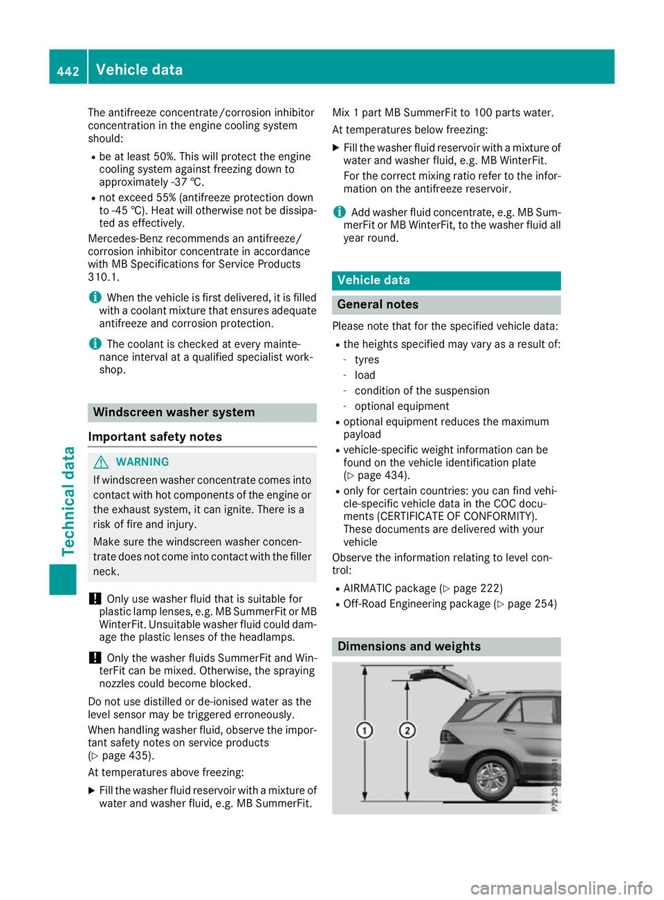
Please note that for the specified vehicle data:
R the heights specified may vary as a result of:
- tyres
- load
- condition of the suspension
- optional equipment
R optional equipment reduces the maximum
payload
R vehicle-specific weight information can be
found on the vehicle identification plate
(Y page 434).
R only for certain countries: you can find vehi-
cle-specific vehicle data in the COC docu-
ments (CERTIFICATE OF CONFORMITY).
These documents are delivered with your
vehicle
Observe the information relating to level con-
trol:
R AIRMATIC package (Y page 222)
R Off-Road Engineering package (Y page 254) Dimensions and weights442
Vehicle dataTechnical data
Page 446 of 453
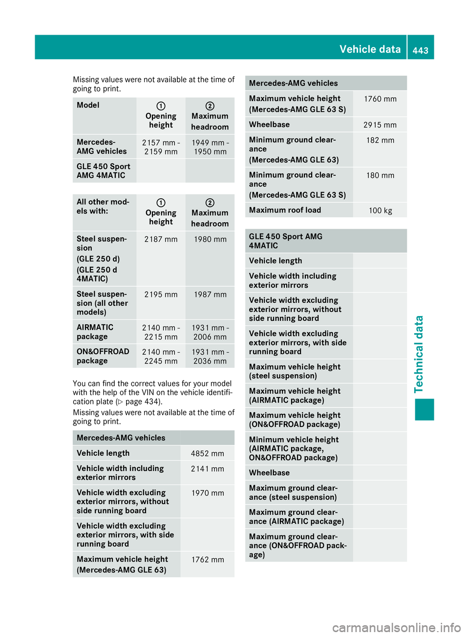
Missing values were not available at the time of
going to print. Model
:
:
Opening height ;
;
Maximum
headroom Mercedes-
AMG vehicles
2157 mm -
2159 mm 1949 mm -
1950 mm GLE 450 Sport
AMG 4MATIC
All other mod-
els with:
: :
Opening height ;
;
Maximum
headroom Steel suspen-
sion
(GLE 250 d)
(GLE 250 d
4MATIC)
2187 mm 1980 mm
Steel suspen-
sion (all other
models)
2195 mm 1987 mm
AIRMATIC
package
2140 mm -
2215 mm 1931 mm -
2006 mm ON&OFFROAD
package
2140 mm -
2245 mm 1931 mm -
2036 mm You can find the correct values for your model
with the help of the VIN on the vehicle identifi-
cation plate (Y page 434).
Missing values were not available at the time of
going to print. Mercedes-AMG vehicles
Vehicle length
4852 mm
Vehicle width including
exterior mirrors
2141 mm
Vehicle width excluding
exterior mirrors, without
side running board
1970 mm
Vehicle width excluding
exterior mirrors, with side
running board
Maximum vehicle height
(Mercedes-AMG GLE 63)
1762 mm Mercedes-AMG vehicles
Maximum vehicle height
(Mercedes-AMG GLE 63 S)
1760 mm
Wheelbase
2915 mm
Minimum ground clear-
ance
(Mercedes-AMG GLE 63)
182 mm
Minimum ground clear-
ance
(Mercedes-AMG GLE 63 S)
180 mm
Maximum roof load
100 kg
GLE 450 Sport AMG
4MATIC
Vehicle length
Vehicle width including
exterior mirrors
Vehicle width excluding
exterior mirrors, without
side running board
Vehicle width excluding
exterior mirrors, with side
running board
Maximum vehicle height
(steel suspension)
Maximum vehicle height
(AIRMATIC package)
Maximum vehicle height
(ON&OFFROAD package)
Minimum vehicle height
(AIRMATIC package,
ON&OFFROAD package)
Wheelbase
Maximum ground clear-
ance (steel suspension)
Maximum ground clear-
ance (AIRMATIC package)
Maximum ground clear-
ance (ON&OFFROAD pack-
age) Vehicle data
443Technical data Z
Page 447 of 453
GLE 450 Sport AMG
4MATIC Minimum ground clear-
ance (AIRMATIC package,
ON&OFFROAD package)
Maximum roof load
All other models
Vehicle length
4819 mm
Vehicle width including
exterior mirrors
2141 mm
Vehicle width excluding
exterior mirrors, without
side running board
1935 mm
Vehicle width excluding
exterior mirrors, with side
running board
1951 mm
Maximum vehicle height
(steel suspension)
(GLE 250 d)
(GLE 250 d 4MATIC)
1788 mm
Maximum vehicle height
(steel suspension)
(all other models)
1796 mm
Maximum vehicle height
(AIRMATIC package)
1818 mm
Maximum vehicle height
(ON&OFFROAD package)
1848 mm
Minimum vehicle height
(AIRMATIC package,
ON&OFFROAD package)
1758 mm
Wheelbase
2915 mm
Maximum ground clear-
ance (steel suspension)
(GLE 250 d)
(GLE 250 d 4MATIC) 191 mm
Maximum ground clear-
ance (steel suspension)
(all other models) 202 mm
Maximum ground clear-
ance (AIRMATIC package)
255 mm All other models
Maximum ground clear-
ance (ON&OFFROAD pack-
age)
285 mm
Minimum ground clear-
ance (AIRMATIC package,
ON&OFFROAD package)
180 mm
Maximum roof load
100 kg
Vehicle data for off-road driving
Fording depth
! The depth of water must not exceed the
value specified in the table. Note that the
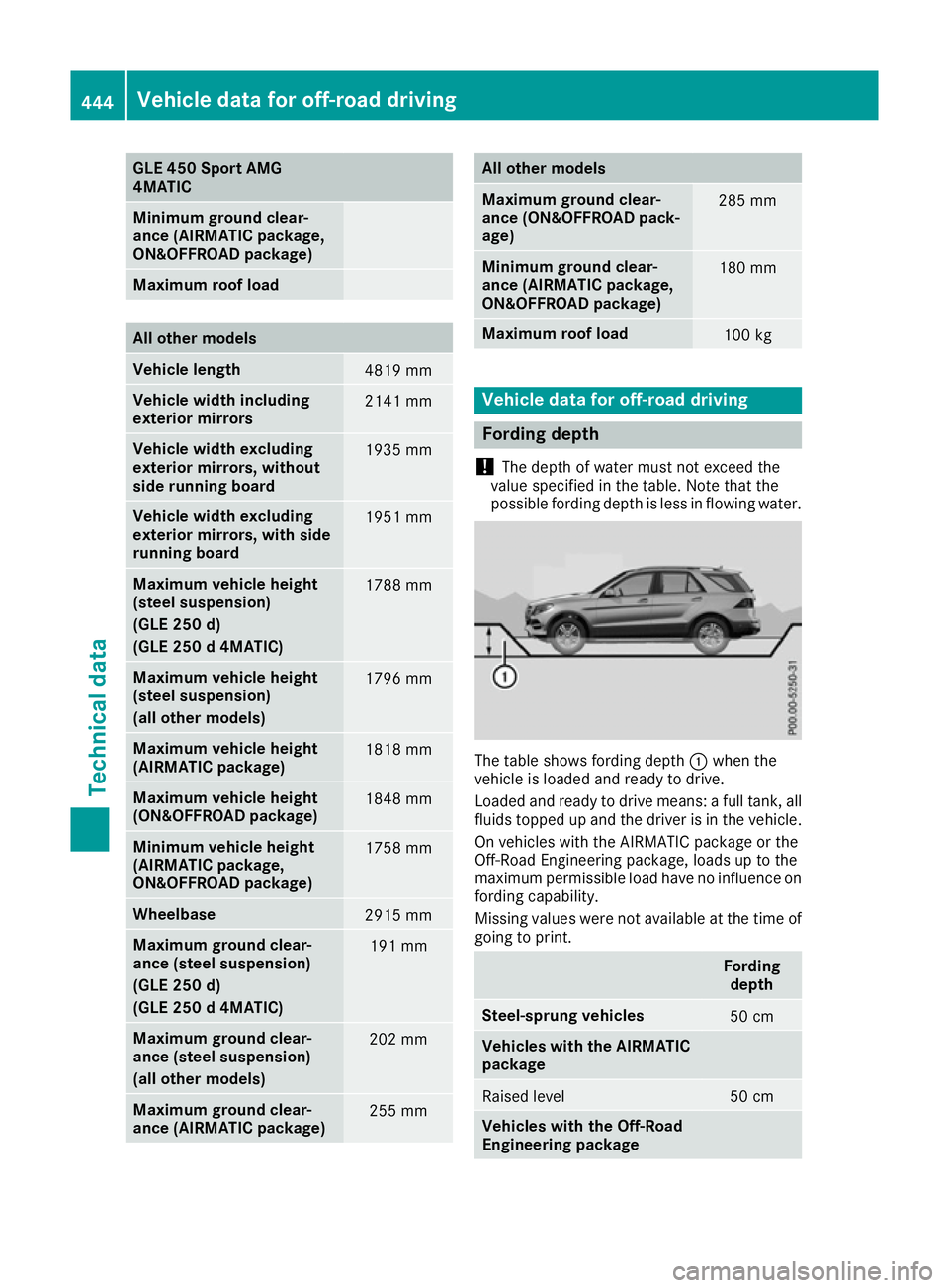
possible fording depth is less in flowing water. The table shows fording depth
:when the
vehicle is loaded and ready to drive.
Loaded and ready to drive means: a full tank, all fluids topped up and the driver is in the vehicle.
On vehicles with the AIRMATIC package or the
Off-Road Engineering package, loads up to the
maximum permissible load have no influence on fording capability.
Missing values were not available at the time of
going to print. Fording
depth Steel-sprung vehicles
50 cm
Vehicles with the AIRMATIC
package Raised level 50 cm
Vehicles with the Off-Road
Engineering package444
Vehicle data for off-road drivingTechnical data