2015 MERCEDES-BENZ G-CLASS SUV height
[x] Cancel search: heightPage 87 of 274

interrupted, e.g. if the battery has been com-pletely discharged or disconnected.
X Make sure that the cup holder on the center
console is folded down ( Ypage 197).
X Move the seat as far forward as possible
and the head restraint in as far as possible.
Rear seat head restraints
Important safety notes
GWARNING
If head restraints are not installed and adjus-
ted correctly, they cannot provide protection
as intended. There is an increased risk of
injury in the head and neck area, e.g. in the
event of an accident or when braking.
Always drive with the head restraints instal-
led. Before driving off, make sure for every
vehicle occupant that the center of the head
restraint supports the back of the head at
about eye level.
Observe the following when adjusting the
head restraints: X Do not rotate the head restraints of the
front and rear seats.
Otherwise, you cannot adjust the height
and angle of the head restraints correctly.
X Adjust the head restraint so that it is as
close as possible to your head.
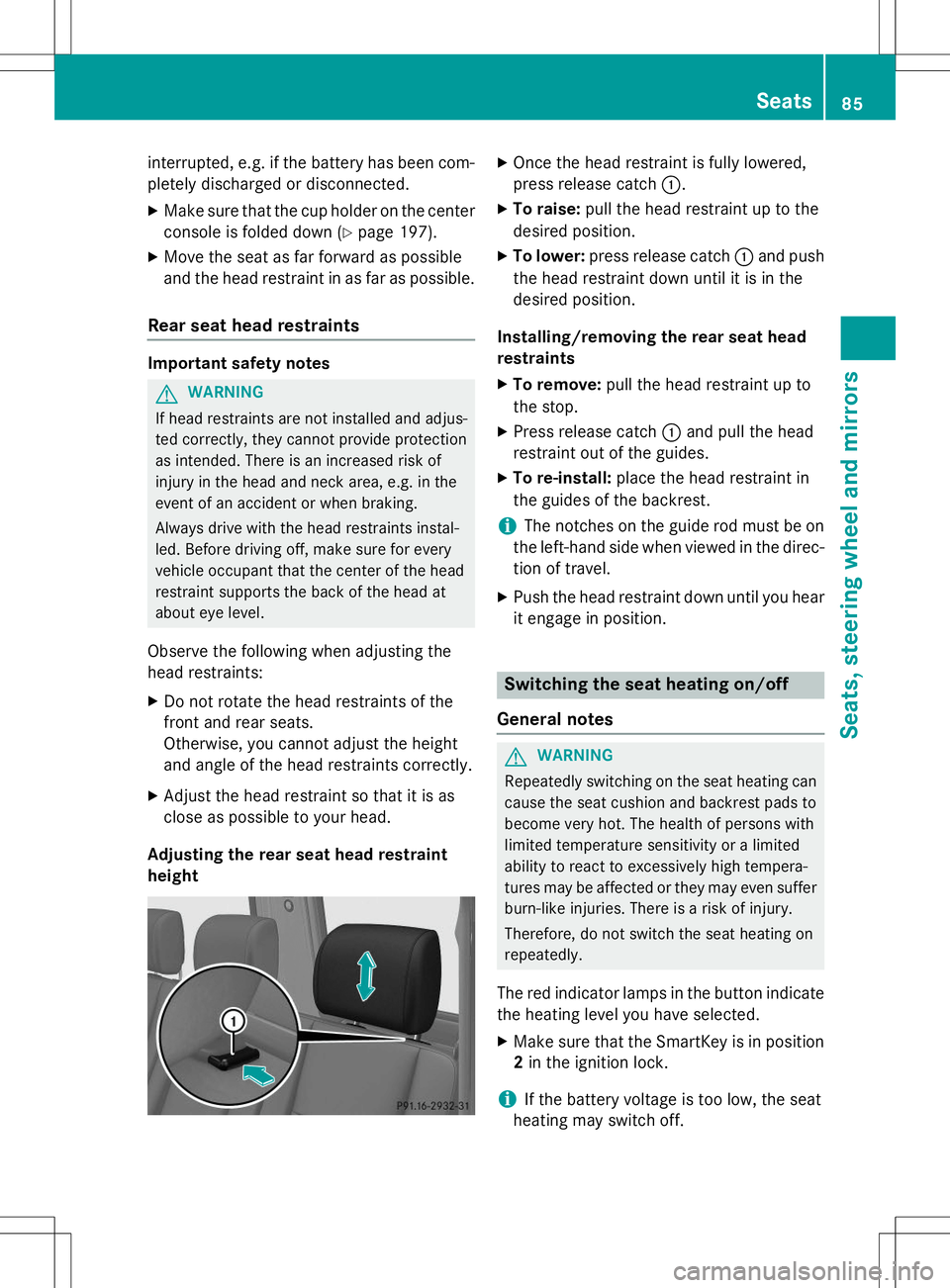
Adjusting the rear seat head restraintheight
X Once the head restraint is fully lowered,
press release catch :.
X To raise: pull the head restraint up to the
desired position.
X To lower: press release catch :and push
the head restraint down until it is in the
desired position.
Installing/removing the rear seat head
restraints
X To remove: pull the head restraint up to
the stop.
X Press release catch :and pull the head
restraint out of the guides.
X To re-install: place the head restraint in
the guides of the backrest.
iThe notches on the guide rod must be on
the left-hand side when viewed in the direc- tion of travel.
X Push the head restraint down until you hear
it engage in position.
Switching the seat heating on/off
General notes
GWARNING
Repeatedly switching on the seat heating can
cause the seat cushion and backrest pads to
become very hot. The health of persons with
limited temperature sensitivity or a limited
ability to react to excessively high tempera-
tures may be affected or they may even suffer burn-like injuries. There is a risk of injury.
Therefore, do not switch the seat heating on
repeatedly.
The red indicator lamps in the button indicate the heating level you have selected.
X Make sure that the SmartKey is in position
2 in the ignition lock.
iIf the battery voltage is too low, the seat
heating may switch off.
Seats85
Seats, steering wheel and mirrors
Z
Page 142 of 274

iAlso observe the height of the trailer cou-
pling and the trailer manufacturer's instruc- tions.
iDepending on the height of the trailer
coupling, you may have to turn the ball cou-
pling 180° to install it on the ball coupling
carrier. The assembly is otherwise identi-
cal.
Installing the ball coupling
GWARNING
If the ball coupling is not installed correctly or not secured with the bolt provided and the
corresponding spring cotter, the trailer may
come loose. There is a risk of an accident.
Always install and secure the ball coupling as
described. Before every journey, ensure that
the ball coupling is secured with the bolt and
the corresponding spring cotter.
GWARNING
If the ball coupling is not correctly installed
and secured, it can come loose during the
journey and endanger other road users. There is a risk of an accident and injury.
Always install and secure the ball coupling as
described. Before every journey, ensure that
the ball coupling is secured with the bolt and
the corresponding spring cotter.
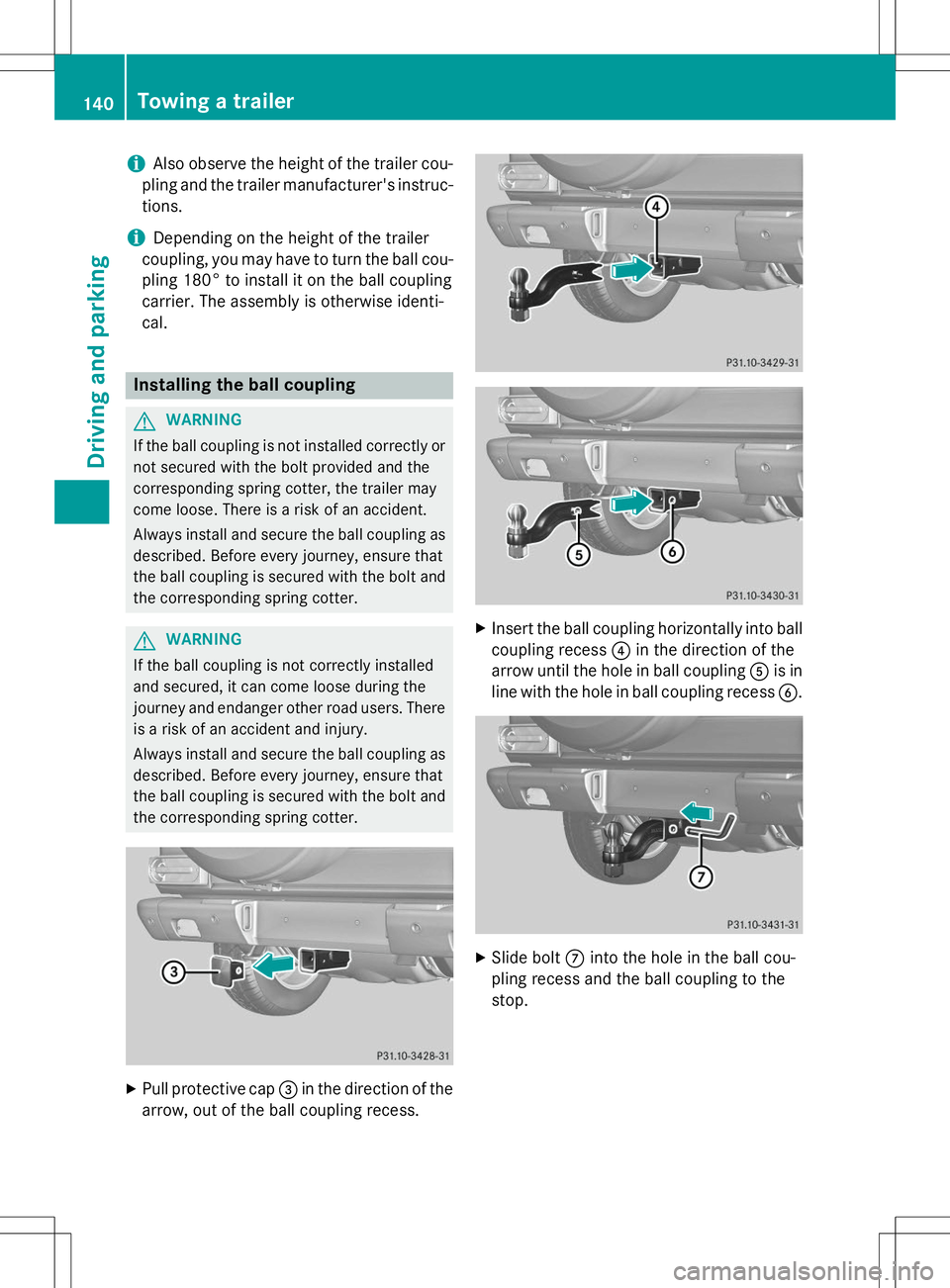
X Pull protective cap =in the direction of the
arrow, out of the ball coupling recess.
X Insert the ball coupling horizontally into ball
coupling recess ?in the direction of the
arrow until the hole in ball coupling Ais in
line with the hole in ball coupling recess B.
X
Slide bolt Cinto the hole in the ball cou-
pling recess and the ball coupling to the
stop.
140Towing a trailer
Driving an d parking
Page 207 of 274

Opening the hood
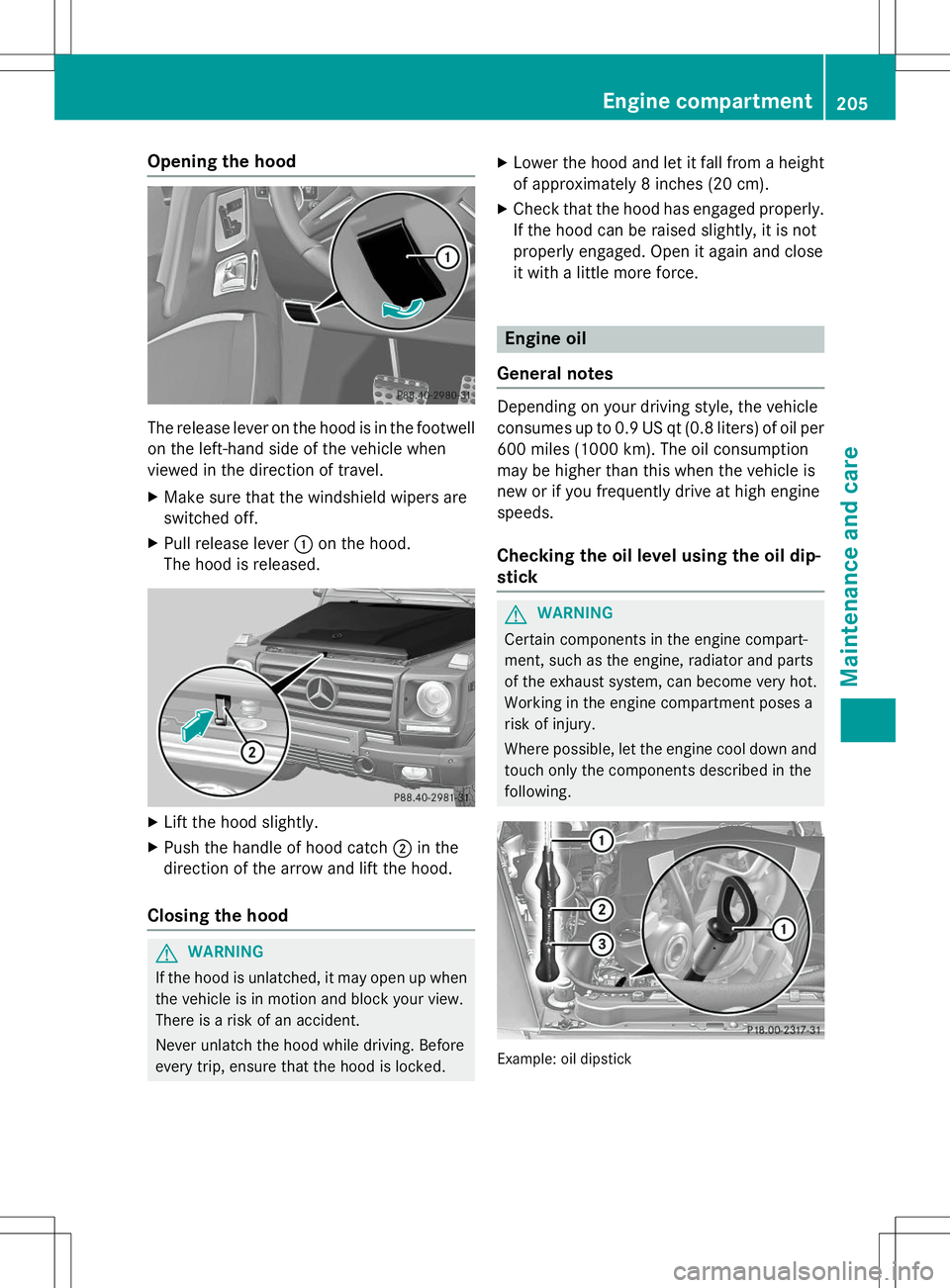
The release lever on the hood is in the footwellon the left-hand side of the vehicle when
viewed in the direction of travel.
X Make sure that the windshield wipers are
switched off.
X Pull release lever :on the hood.
The hood is released.
X Lift the hood slightly.
X Push the handle of hood catch ;in the
direction of the arrow and lift the hood.
Closing the hood
GWARNING
If the hood is unlatched, it may open up when the vehicle is in motion and block your view.
There is a risk of an accident.
Never unlatch the hood while driving. Before
every trip, ensure that the hood is locked. X
Lower the hood and let it fall from a height
of approximately 8 inches (20 cm).
X Check that the hood has engaged properly.
If the hood can be raised slightly, it is not
properly engaged. Open it again and close
it with a little more force.
Engine oil
General notes
Depending on your driving style, the vehicle
consumes up to 0.9 US qt (0.8 liters) of oil per 600 miles (1000 km). The oil consumption
may be higher than this when the vehicle is
new or if you frequently drive at high enginespeeds.
Checking the oil level using the oil dip-stick
GWARNING
Certain components in the engine compart-
ment, such as the engine, radiator and parts
of the exhaust system, can become very hot.
Working in the engine compartment poses a
risk of injury.
Where possible, let the engine cool down and touch only the components described in the following.
Example: oil dipstick
Engine compartment205
Maintenance and care
Z
Page 246 of 274

which all passenger car tires must meet underthe Federal Motor Vehicle Safety Standard
No. 109. Grades B and A represent higher
levels of performance on the laboratory test
wheel than the minimum required by law.
Tire labeling
Overview of tire labeling
:Uniform tire Quality Grading Standard ( Y page 248)
;DOT tire Identification Number(Y page 247)
=Maximum tire load ( Ypage 246)
?Maximum tire pressures ( Ypage 235)
AManufacturer
BTire material ( Ypage 247)
CTire size designation, load-bearing capa-
city and speed rating ( Ypage 244)
DLoad identification ( Ypage 246)
ETire name
The markings described above are on the tire in addition to the tire name (sales designa-
tion) and the manufacturer's name.
iTire data is vehicle-specific and may devi-
ate from the data in the example.
Tire size designation, load-bearing
capacity and speed rating
GWARNING
Exceeding the stated tire load-bearing capa-
city and the approved maximum speed could
lead to tire damage or the tire bursting. There is a risk of accident.
Therefore, only use tire types and sizes
approved for your vehicle model. Observe the
tire load rating and speed rating required for
your vehicle.
:Tire width
;Height-width ratio in percentage
=Tire code
?Rim diameter
ALoad bearing index
BSpeed rating
General: depending on the manufacturer's
standards, a letter is imprinted into the tire
wall before the size description.
If there is no letter preceding the size descrip-
tion (as shown above): these are passenger
vehicle tires according to European manufac-
turing standards.
If "P" precedes the size description:
passenger vehicle tires according to U.S.
manufacturing standards.
If "P" precedes the size description: light
truck tires according to U.S. manufacturing
standards.
If "T" precedes the size description: these are
compact emergency spare wheels at high tire
244Tire labeling
Wheels and tires
Page 247 of 274

pressure, to be used only temporarily in an
emergency.
Tire width:tire width:shows the nominal
tire width in millimeters.
Height-width ratio: height-width ratio;is
the ratio between tire height and tire width.
The aspect ratio is calculated by dividing the
tire width by the tire height. The resulting
quotient is given as a percentage.
Tire code: tire code=shows the tire type.
"R" represents radial tires; "D" represents
diagonal tires; "B" represents diagonal radial
tires.
Optionally, tires with a maximum speed of
over 149 mph (240 km/ h)may have "ZR" in
the size description, depending on the man-
ufacturer (e.g. 245/40 ZR 18).
Rim diameter: rim diameter?is the diam-
eter of the bead seat, not the diameter of the
rim flange. The rim diameter is specified in
inches (in).
The load-bearing index: load-bearing index
A (also load index), is a code that contains
the maximum load-bearing capacity of a tire.
Do not overload the tires by exceeding the
specified load limit. The maximum permissi-
ble load can be found on the vehicle's Tire and
Loading Information placard on the B-pillar on the driver's side ( Ypage 238).
Example:
Load-bearing index 91 indicates a maximum
load of 1,356 lb (615 kg) that the tires can
bear. For further information on the maximum tire load in kilograms and pounds, see( Y page 246).
For further information on the load bearing
index, see "Load index" ( Ypage 246).
Speed rating: speed ratingBspecifies the
approved maximum speed of the tire.
iTire data is vehicle-specific and may devi-
ate from the data in the example.
Regardless of the speed rating, always
observe the speed limits. Drive carefully and
adapt your driving style to the traffic condi-tions.
iSince 2009, tires in Europe which corre-
spond to the noise limitations of Directive
ECE-R 117 show an >>S<< (Sound) mark.
This identification follows the type approval number and has no connection with the
speed rating.
Summer tires
IndexSpeed rating
Qup to 100 mph (160 km/h)
Rup to 106 mph (170 km/h)
Sup to 112 mph (180 km/h)
Tup to 118 mph (190 km/h)
Hup to 130 mph (210 km/h)
Vup to 149 mph (240 km/h)
Wup to 168 mph (270 km/h)
Yup to 186 mph (300 km/h)
ZR...Yup to 186 mph (300 km/h)
ZR...(..Y)over 186 mph (300 km/h)
ZRover 149 mph (240 km/h)
R Optionally, tires with a maximum speed of
over 149 mph (240 km/h) may have "ZR" in
the size description, depending on the
manufacturer (e.g. 245/40 ZR18).
The service specification is made up of
load-bearing index Aand speed rating B.
R If the size description of your tire includes
"ZR" and there are no service specifica-
tions, ask the tire manufacturer in order to
find out the maximum speed.
If a service specification is available, the
maximum speed is limited according to the
speed rating in the service specification.
Example: 245/40 ZR18 97 Y.In this exam-
ple, "97 Y" is the service specification. The letter "Y" represents the speed rating and
Tire labeling245
Wheels and tires
Z
Page 251 of 274

Maximum loaded vehicle weight
The maximum weight is the sum of: Rthe curb weight of the vehicle
R the weight of the accessories
R the load limit
R the weight of the factory installed optional
equipment
Kilopascal (kPa)
Metric unit for tire pressure. 6.9 kPa corre-
sponds to 1 psi. Another unit for tire pressure
is bar. 100 kilopascals (kPa) are the equiva-
lent of 1 bar.
Load index
In addition to the load-bearing index, the load index may also be imprinted on the sidewall of
the tire. This specifies the load-bearing capa- city more precisely.
Curb weight
The weight of a vehicle with standard equip-
ment including the maximum capacity of fuel,oil and coolant. It also includes the air-condi- tioning system and optional equipment if
these are installed in the vehicle, but does notinclude passengers or luggage.
Maximum load rating
The maximum load rating is the maximum
permissible weight in kilograms or lbs for
which a tire is approved.
Maximum permissible tire pressure
Maximum permissible tire pressure for one tire.
Maximum load on one tire
Maximum load on one tire. This is calculated
by dividing the maximum axle load of one axleby two.
PSI (pounds per square inch)
A standard unit of measure for tire pressure.
Aspect ratio
Relationship between tire height and tire
width in percent.
Tire pressure
This is pressure inside the tire applying an
outward force to each square inch of the tire's surface. The tire pressure is specified in
pounds per square inch (psi), in kilopascals
(kPa) or in bar. The tire pressure should only
be corrected when the tires are cold.
Cold tire pressure
The tires are cold:
R if the vehicle has been parked without
direct sunlight on the tires for at least three
hours and
R if the vehicle has not been driven further
than 1 mile (1.6 km)
Tread
The part of the tire that comes into contact
with the road.
Bead
The tire bead ensures that the tire sits
securely on the wheel. There are several steel
wires in the bead to prevent the tire from
coming loose from the wheel rim.
Sidewall
The part of the tire between the tread and the
bead.
Weight of optional extras
The combined weight of those optional extras
that weigh more than the replaced standard
parts and more than 2.3 kg (5 lbs). These
optional extras, such as high-performance
Tire labeling249
Wheels and tires
Z
Page 254 of 274

rectly, the jack could tip over with the vehi-cle raised.
R The jack is designed only to raise and hold
the vehicle for a short time while a wheel
is being changed. It is not suited for per-
forming maintenance work under the vehi-
cle.
R Avoid changing the wheel on uphill and
downhill slopes.
R Before raising the vehicle, secure it from
rolling away by applying the parking brake
and inserting wheel chocks. Never disen-
gage the parking brake while the vehicle is
raised.
R The jack must be placed on a firm, flat and
non-slip surface. On a loose surface, a
large, load-bearing underlay must be used.
On a slippery surface, a non-slip underlay
must be used, e.g. rubber mats.
R Do not use wooden blocks or similar
objects as a jack underlay. Otherwise, the
jack will not be able to achieve its load-
bearing capacity due to the restricted
height.
R Make sure that the distance between the
underside of the tires and the ground does
not exceed 1.2 in (3 cm).
R Never place your hands and feet under the
raised vehicle.
R Never lie under the raised vehicle.
R Never start the engine when the vehicle is
raised.
R Never open or close a door or the tailgate
when the vehicle is raised.
R Make sure that no persons are present in
the vehicle when the vehicle is raised.
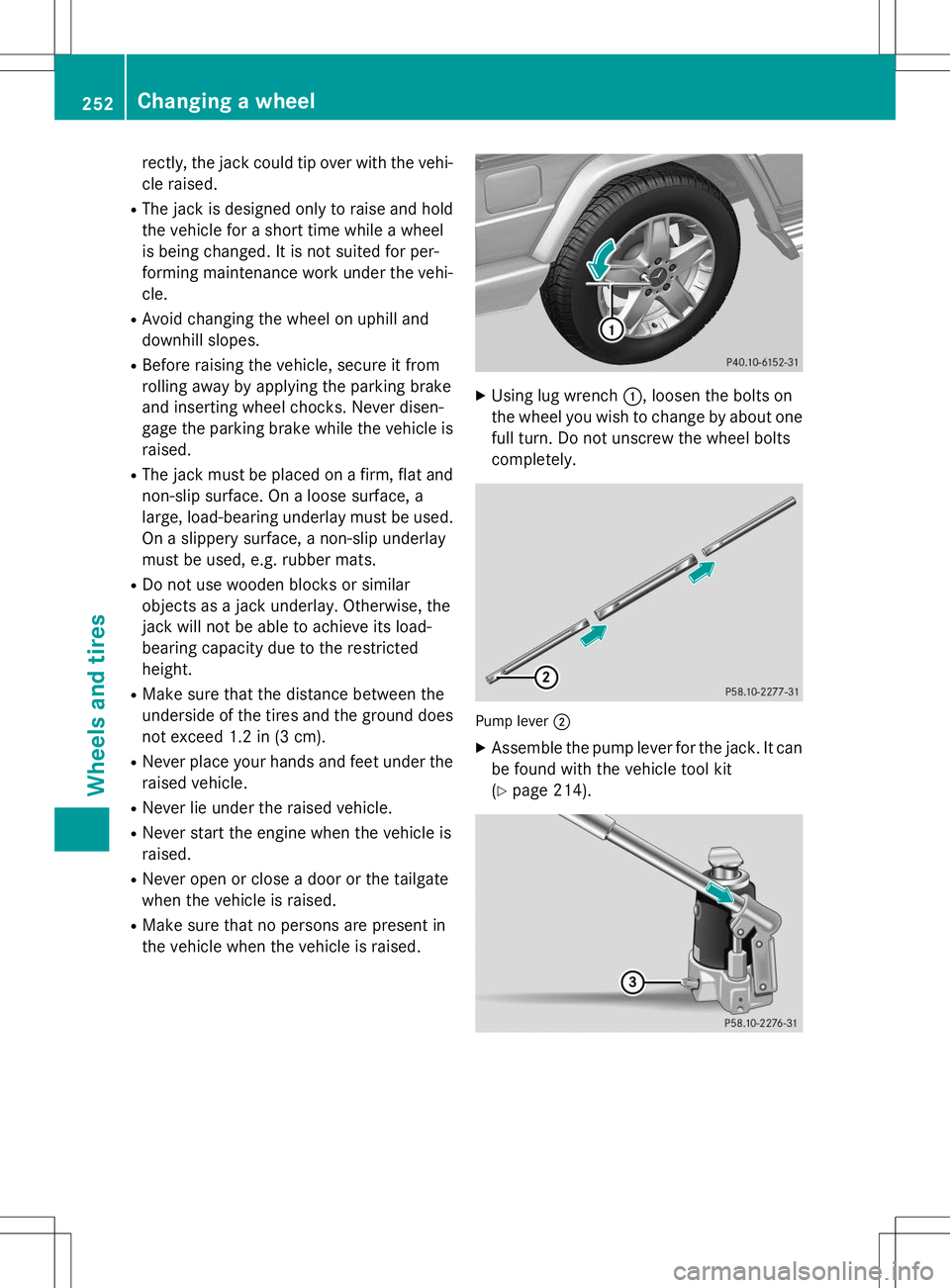
XUsing lug wrench :, loosen the bolts on
the wheel you wish to change by about one full turn. Do not unscrew the wheel bolts
completely.
Pump lever ;
X
Assemble the pump lever for the jack. It can
be found with the vehicle tool kit ( Y page 214).
252Changing a wheel
Wheels and tires
Page 268 of 274

At temperatures above freezing:X Fill the washer fluid reservoir with a mixture
of water and windshield washer fluid, e.g.
MB SummerFit.
X Add 1 part MB SummerFit to 100 parts
water.
At temperatures below freezing:
X Fill the washer fluid reservoir with a mixture
of water and washer fluid, e.g. MB Winter-Fit.
For the correct mixing ratio refer to the
information on the antifreeze reservoir.
iAdd washer fluid concentrate, e.g. MB
SummerFit or MB WinterFit, to the washer
fluid all year round.
Vehicle data
General notes
Please note that for the specified vehicle
data:
R the heights specified may vary as a resultof:
- tires
- load
- condition of the suspension
- optional equipment
R the vehicle length specified includes the
front license plate adapter.
Dimensions and weights
G 550G 63 AMG
: Upper-
edge clear-
ance75 in -
78.9 in
(1905 mm - 2005 mm)74.5 in - 78.4 in
(1892 mm - 1992 mm)
; Lower-
edge clear-
ance26.8 in - 30.7 in
(680 mm - 780 mm)26.3 in -30.2 in
(667 mm - 767 mm)
= Range of
movement36.7 in
(931 mm)36.7 in
(931 mm)
G 550
Vehicle length183.5 in
(4662 mm)
Vehicle width including
exterior mirrors80.9 in
(2055 mm)
Vehicle height76.8 in
(1951 mm)
Wheelbase112.2 in
(2850 mm)
Minimum ground clear-
ance8.1 in
(205 mm)
Turning radius44.6 ft
(13.60 m)
Gross vehicle weigh t rat-
ing (GVWR)7054.8 lb
(3200 kg)
Gross axle weight rating
(GAWR), front3196.7 lb
(1450 kg)
Gross axle weight rating
(GAWR), rear4188.8 lb
(1900 kg)
G 63 AMG
Vehicle length187.8 in
(4769 mm)
Vehicle width including
exterior mirrors80.9 in
(2056 mm)
266Vehicle data
Technical data