2015 MERCEDES-BENZ E-CLASS COUPE transmission
[x] Cancel search: transmissionPage 185 of 345
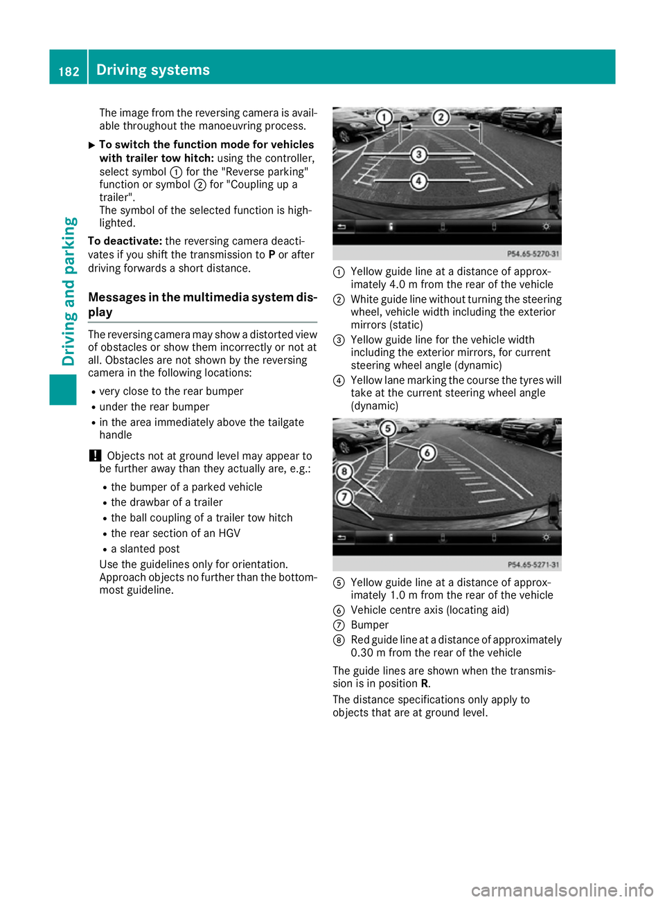
The image from the reversing camera is avail-
able throughout the manoeuvring process.
X To switch the function mode for vehicles
with trailer tow hitch: using the controller,
select symbol :for the "Reverse parking"
function or symbol ;for "Coupling up a
trailer".
The symbol of the selected function is high-
lighted.
To deactivate: the reversing camera deacti-
vates if you shift the transmission to Por after
driving forwards a short distance.
Messages in the multimedia system dis-
play The reversing camera may show a distorted view
of obstacles or show them incorrectly or not at
all. Obstacles are not shown by the reversing
camera in the following locations:
R very close to the rear bumper
R under the rear bumper
R in the area immediately above the tailgate
handle
! Objects not at ground level may appear to
be further away than they actually are, e.g.:
R the bumper of a parked vehicle
R the drawbar of a trailer
R the ball coupling of a trailer tow hitch
R the rear section of an HGV
R a slanted post
Use the guidelines only for orientation.
Approach objects no further than the bottom- most guideline. :
Yellow guide line at a distance of approx-
imately 4.0 m from the rear of the vehicle
; White guide line without turning the steering
wheel, vehicle width including the exterior
mirrors (static)
= Yellow guide line for the vehicle width
including the exterior mirrors, for current
steering wheel angle (dynamic)
? Yellow lane marking the course the tyres will
take at the current steering wheel angle
(dynamic) A
Yellow guide line at a distance of approx-
imately 1.0 m from the rear of the vehicle
B Vehicle centre axis (locating aid)
C Bumper
D Red guide line at a distance of approximately
0.30 m from the rear of the vehicle
The guide lines are shown when the transmis-
sion is in position R.
The distance specifications only apply to
objects that are at ground level. 182
Driving systemsDriving and parking
Page 189 of 345

R
Top view and image from the reversing cam-
era (130° viewing angle)
R Top view and image from the front camera
(130° viewing angle without displaying the
maximum steering wheel angle)
R Top view and enlarged rear view
R Top view and enlarged front view
R Top view and trailer view (vehicles with trailer
tow hitch)
R Top view and images from the rear-facing side
cameras (rear wheel view)
R Top view and images from the forward-facing
side cameras (front wheel view)
When the function is active and you shift the
transmission from Dor Rto N, the dynamic
guide lines are hidden.
When you change between transmission posi-
tions Dand R, you see the previously selected
front or rear view.
Distances measured by PARKTRONIC will also
be optically displayed:
R as red or yellow brackets around the vehicle
symbol in top view in split-screen mode or
R at the bottom right as red or yellow brackets
around the vehicle symbol in full-screen mode
The line thickness and colour of the brackets
show how far the vehicle is from an object.
R yellow brackets with thin lines: PARKTRONIC
is active
R yellow brackets with normal lines: an object is
present in close range of the vehicle
R red line: an object is present in the immediate
close range of the vehicle
Important safety notes The 360° camera is only an aid and may show a
distorted view of obstacles, show them incor-
rectly or not at all. The 360° camera is not a
substitute for attentive driving.
The responsibility for safe manoeuvring and
parking remains with you. Make sure that there are no persons, animals or objects in range
while manoeuvring and parking.
You are always responsible for safety, and must
always pay attention to your surroundings when parking and manoeuvring. This applies to the
areas behind, in front of and beside the vehicle.
You could otherwise endanger yourself and oth- ers. The 360° camera will not function or will func-
tion only in a limited manner:
R if the doors are open
R if the exterior mirrors are folded in
R if the boot lid is open
R in heavy rain, snow or fog
R at night or in very dark places
R if the cameras are exposed to very bright light
R if the area is lit by fluorescent bulbs or LED
lighting (the display may flicker)
R if there is a sudden change in temperature,
e.g. when driving into a heated garage in win-
ter
R if the camera lenses are dirty or covered
R if the vehicle components in which the cam-
eras are fitted are damaged. In this event,
have the camera position and setting checked at a qualified specialist workshop.
Do not use the 360° camera under such cir-
cumstances. You could otherwise injure others
or damage objects when parking the vehicle.
Guide lines are always shown at road level. In
trailer mode, the guide lines are shown at the
level of the trailer coupling.
The field of vision and other functions of the
camera system may be restricted due to addi-
tional accessories on the rear of the vehicle (e.g.
licence plate holder, bicycle rack).
On vehicles with height-adjustable suspension,
due to the technical conditions, leaving the
standard height can result in:
R inaccuracies in the guide lines
R inaccuracies in the display of generated
images (top view)
Activation conditions The 360° camera image can be displayed if:
R your vehicle is equipped with a 360° camera
R the key is in position 2in the ignition lock
R the multimedia system is switched on
R the 360° camera
360° camera function is switched on
Activating the 360° camera X
Press the Øbutton in the centre console
for longer than two seconds.
The following appears depending on whether
transmission position Dor Ris selected: 186
Driving systemsDriving and parking
Page 190 of 345
R
a split-screen with top view and the image
from the front camera or
R a split-screen with top view and the image
from the reversing camera
or
X Press the Øbutton in the centre console.
The vehicle menu appears.
X Select 360°
360° camera camera and press 7to confirm.
The following appears depending on whether transmission position Dor Ris selected:
R a split-screen with top view and the image
from the front camera or
R a split-screen with top view and the image
from the reversing camera
Switching on the 360° camera using
reverse gear You can show images from the 360° camera
automatically by engaging reverse gear.
X Make sure that the key is in position 2in the
ignition lock.
X Make sure that the Activation by R gear
Activation by R gear
function is selected in the multimedia system (see the separate operating instructions).
X To show the 360° camera image: engage
reverse gear.
The area behind the vehicle is shown in the
multimedia system display in split-screen
mode. You see the top view of the vehicle and the image from the reversing camera.
Selecting the split-screen and full
screen displays Switching between split screen views
X To switch to the line with the vehicle icons:
slide 5the controller.
X To select one of the vehicle icons: turn 3
the controller.
X To switch to 180° view
180° view :turn 3 the con-
troller to select 180° view
180° view and press7to
confirm.
i The
180° 180° view
viewoption is only available in the
following views:
R Top view with image from the reversing
camera
R Top view with image from the front camera Messages in the multimedia system dis-
play Important safety notes
The system may show a distorted view of obsta-
cles or show them incorrectly or not at all.
Obstacles are not shown by the system in the
following locations:
R under the front and rear bumpers
R very close to the front and rear bumpers
R in the area immediately above the handle on
the boot lid
R very close to the exterior mirrors
R in the transitional areas between the various
cameras in the virtual top view
! Objects not at ground level may appear to
be further away than they actually are, e.g.:
R the bumper of a parked vehicle
R the drawbar of a trailer
R the ball coupling of a trailer tow hitch
R the rear section of an HGV
R a slanted post
Use the guidelines only for orientation.
Approach objects no further than the bottom- most guideline.
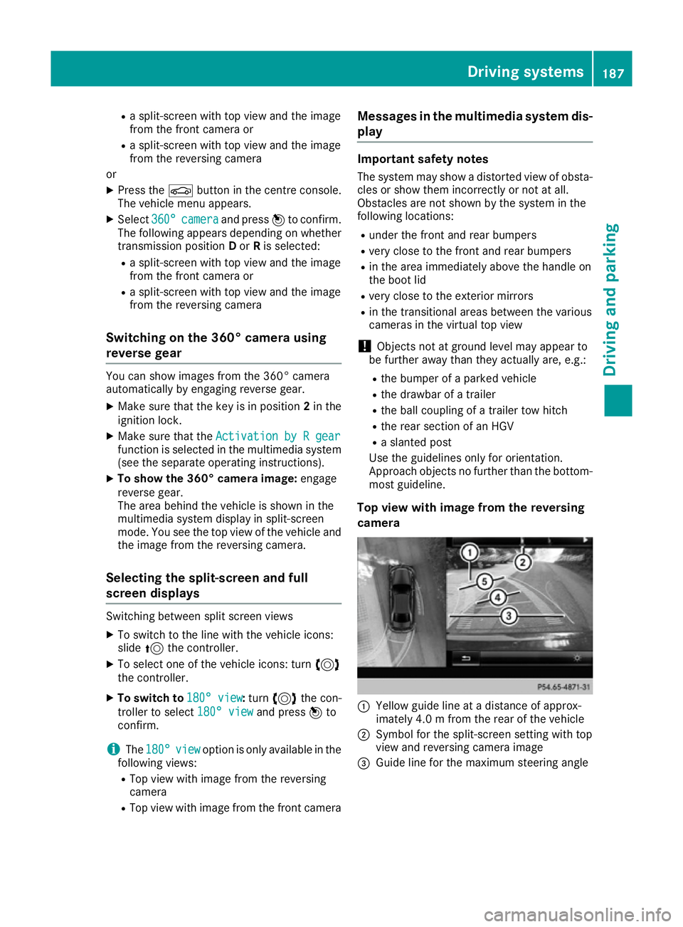
Top view with image from the reversing
camera :
Yellow guide line at a distance of approx-
imately 4.0 m from the rear of the vehicle
; Symbol for the split-screen setting with top
view and reversing camera image
= Guide line for the maximum steering angle Driving systems
187Driving and parking Z
Page 192 of 345
i
You can also select the side camera setting
for the rear-facing view.
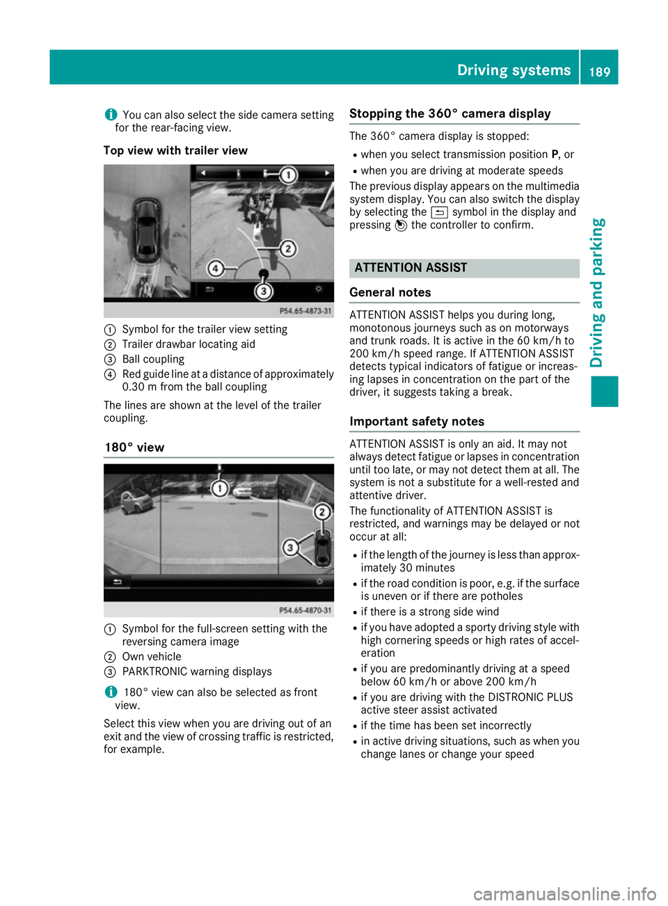
Top view with trailer view :
Symbol for the trailer view setting
; Trailer drawbar locating aid
= Ball coupling
? Red guide line at a distance of approximately
0.30 m from the ball coupling
The lines are shown at the level of the trailer
coupling.
180° view :
Symbol for the full-screen setting with the
reversing camera image
; Own vehicle
= PARKTRONIC warning displays
i 180° view can also be selected as front
view.
Select this view when you are driving out of an
exit and the view of crossing traffic is restricted,
for example. Stopping the 360° camera display The 360° camera display is stopped:
R
when you select transmission position P, or
R when you are driving at moderate speeds
The previous display appears on the multimedia system display. You can also switch the display
by selecting the &symbol in the display and
pressing 7the controller to confirm. ATTENTION ASSIST
General notes ATTENTION ASSIST helps you during long,
monotonous journeys such as on motorways
and trunk roads. It is active in the 60 km/h to
200 km/h speed range. If ATTENTION ASSIST
detects typical indicators of fatigue or increas-
ing lapses in concentration on the part of the
driver, it suggests taking a break.
Important safety notes ATTENTION ASSIST is only an aid. It may not
always detect fatigue or lapses in concentration
until too late, or may not detect them at all. The
system is not a substitute for a well-rested and
attentive driver.
The functionality of ATTENTION ASSIST is
restricted, and warnings may be delayed or not
occur at all:
R if the length of the journey is less than approx-
imately 30 minutes
R if the road condition is poor, e.g. if the surface
is uneven or if there are potholes
R if there is a strong side wind
R if you have adopted a sporty driving style with
high cornering speeds or high rates of accel-
eration
R if you are predominantly driving at a speed
below 60 km/h or above 200 km/h
R if you are driving with the DISTRONIC PLUS
active steer assist activated
R if the time has been set incorrectly
R in active driving situations, such as when you
change lanes or change your speed Driving systems
189Driving and parking Z
Page 203 of 345
Lane-correcting brake application
G
WARNING
A lane-correcting brake application cannot
always bring the vehicle back into the original lane. There is a risk of an accident.
Always steer, brake or accelerate yourself,
especially if Active Lane Keeping Assist warns
you or makes a lane-correcting brake appli-
cation. G
WARNING
Active Lane Keeping Assist only detects traf-
fic conditions or road users to a limited
extent. In very rare cases, the system may
make an inappropriate brake application, e.g. after intentionally driving over a solid lane
marking. There is a risk of an accident.
An inappropriate brake application may be
interrupted at any time if you steer slightly in
the opposite direction. Always make sure that
there is sufficient distance to the side for
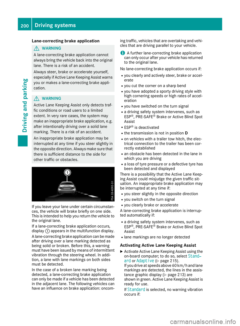
other traffic or obstacles. If you leave your lane under certain circumstan-
ces, the vehicle will brake briefly on one side.
This is intended to help you return the vehicle to
the original lane.
If a lane-correcting brake application occurs,
display :appears in the multifunction display.
A lane-correcting brake application can be made
after driving over a lane marking detected as
being solid or broken. Before this, a warning
must have been issued by means of intermittent
vibration through the steering wheel. In addi-
tion, a lane with lane markings on both sides
must be detected.
In the case of a broken lane marking being
detected, a lane-correcting brake application
can only be made if a vehicle has been detected
in the adjacent lane. The following vehicles can have an influence on brake application: oncom- ing traffic, vehicles that are overtaking and vehi-
cles that are driving parallel to your vehicle.
i A further lane-correcting brake application
can only occur after your vehicle has returned
to the original lane.
No lane-correcting brake application occurs if: R you clearly and actively steer, brake or accel-
erate
R you cut the corner on a sharp bend
R you have adopted a sporty driving style with
high cornering speeds or high rates of accel-
eration
R you have switched on the turn signal
R a driving safety system intervenes, such as
ESP ®
, PRE-SAFE ®
Brake or Active Blind Spot
Assist
R ESP ®
is deactivated
R the transmission is not in position D
R on vehicles with a trailer tow hitch, the elec-
trical connection to the trailer has been cor-
rectly established
R an obstacle has been detected in the lane in
which you are driving
R a loss of tyre pressure or a defective tyre has
been detected and displayed
There is a possibility that the Active Lane Keep-
ing Assist could misjudge the given traffic sit-
uation. An inappropriate brake application may
be interrupted at any time if:
R you steer slightly in the opposite direction
R you switch on the turn signal
R you clearly brake or accelerate
A lane-correcting brake application is interrup-
ted automatically if:
R a driving safety system intervenes, such as
ESP ®
, PRE-SAFE ®
Brake or Active Blind Spot
Assist
R lane markings are no longer detected
Activating Active Lane Keeping Assist
X Activate Active Lane Keeping Assist using the
on-board computer; to do so, select Stand‐
Stand‐
ard ard orAdaptive
Adaptive (Ypage 215).
If you drive at speeds above 60 km/h and lane
markings are detected, the lines in the assis- tance graphic display (Y page 213) are
shown in green. Active Lane Keeping Assist is
ready for use.
If Standard Standard is selected, no warning vibration
occurs if: 200
Driving systemsDriving and parking
Page 207 of 345

X
Place the protective covering on the ball cou-
pling.
Opening the cover: X Turn handle :anti-clockwise and fold down
cover ;.
Unlocking and lowering the ball coupling:
X Pull out release wheel ?.
X Turn release wheel ?anti-clockwise.
The ball coupling unlocks and lowers. Indica-
tor lamp =flashes.
X Press the ball coupling in the direction of the
arrow until it engages behind the bumper.
Indicator lamp =goes out and the message
in the multifunction display disappears. Coupling up a trailer
X Make sure that the transmission is in position
P.
X Apply the parking brake.
X Position the trailer horizontally behind the
vehicle.
X Couple up the trailer.
X Establish the electric connection between the
vehicle and the trailer.
X Check that the trailer lighting system is work-
ing.
A connected trailer is only recognised when
the electrical connection is established cor-
rectly and when the lighting system is working
properly. The function of other systems, such
as ESP ®
, PARKTRONIC and Active Parking
Assist also depends on this. Uncoupling a trailer
G
WARNING
If you uncouple a trailer with an engaged over- run brake, you could trap your hand between
the vehicle and the trailer drawbar. This poses a risk of injury.
Do not uncouple a trailer with an engaged
overrun brake. G
WARNING
Vehicles with level control: If you disconnect the trailer cable, the vehicle
is lowered. This can cause you or others to
become trapped between the vehicle body
and tyres, or underneath the vehicle. This
poses a risk of injury.
Make sure that no-one is in the immediate
vicinity of the wheel arch or underneath the
vehicle when disconnecting the trailer cable.
! Do not disconnect a trailer with an engaged
overrun brake. Otherwise, your vehicle could
be damaged by the rebounding of the overrun
brake.
X Make sure that the transmission is in position
P.
X Apply the parking brake.
X Secure the trailer against rolling away.
X Remove the trailer cable and decouple the
trailer. Trailer power supply
! You can connect accessories to the perma-
nent power supply up to a maximum of 240 W.
You cannot charge a trailer battery using the
power supply.
X To switch the connected power supply on
or off: turn the key in the ignition lock to
position 2or 0respectively (Y page 132).
When it leaves the factory, your vehicle's trailer
socket is equipped with a permanent power
supply and a power supply that is switched on
via the ignition lock.
The permanent power supply is supplied via
trailer socket pin 9.
The power supply that is switched on via the
ignition lock is supplied via trailer socket pin 10.
The trailer's permanent power supply is
switched off in the event of low vehicle supply
voltage and after six hours at the latest.
You can find more information about fitting the
trailer electrics at a qualified specialist work-
shop. Failure check for LEDs
i If LED lamps are fitted in the trailer, a mal-
function message may appear in the multi- 204
Towing a trailerDriving and parking
Page 211 of 345

Back button
% Press briefly:
R Back
R Switches off voice-operated con-
trol for navigation or LINGUA-
TRONIC
R Hides display messages or calls up
the last Trip Tripmenu function used
R Exits the telephone book/redial
memory % Press and hold:
R
Calls up the standard display in the
Trip Trip menu Multifunction display
:
Text field
; Menu bar
= Drive program
? Transmission position
A Permanent display: outside temperature or
speed
X To display menu bar ;:press the =
or ; button on the steering wheel.
If you do not press the buttons any longer,
menu bar ;is faded out after a few seconds.
Text field :shows the selected menu or sub-
menu as well as display messages.
Possible displays in the multifunction dis-
play:
R ZGearshift recommendation for manual
transmission (Y page 140) or for automatic
transmission (shifting manually)
(Y page 144)
R j Active Parking Assist (Y page 176)
R ¯ Cruise control (Y page 156) R
È SPEEDTRONIC (Y page 158)
R _ Adaptive Highbeam Assist Plus
(Y page 109)
R ¤ ECO start/stop function (Y page 135)
R ë HOLD function (Y page 170)
R 120 km/h!
120 km/h! Maximum permissible speed
exceeded (only for certain countries) Menus and submenus
Menu overview
Press the =or; button on the steering
wheel to call up the menu bar and select a menu.
Operating the on-board computer (Y page 207).
Depending on the equipment fitted in the vehi-
cle, you can call up the following menus:
R Trip Trip menu (Y page 208)
R Navi
Navi menu (navigation instructions)
(Y page 210)
R Audio
Audio menu (Y page 211)
R Tel
Tel menu (telephone) (Y page 212)
R Assist.
Assist. menu (assistance) (Y page 213)
R Serv.
Serv. menu (Y page 215)
R Settings
Settings menu (settings) (Y page 216)
The displays are dependent on the multimedia
system. This is why the displays for the Audio
Audio,
Navi
Navi andTel
Tel menus may differ slightly to those
in your vehicle. Trip menu
Standard display X
Press and hold the %button on the steer-
ing wheel until the Trip
Tripmenu with trip
meter :and total distance recorder ;
appears. 208
Menus and submenusOn-board computer and displays
Page 212 of 345
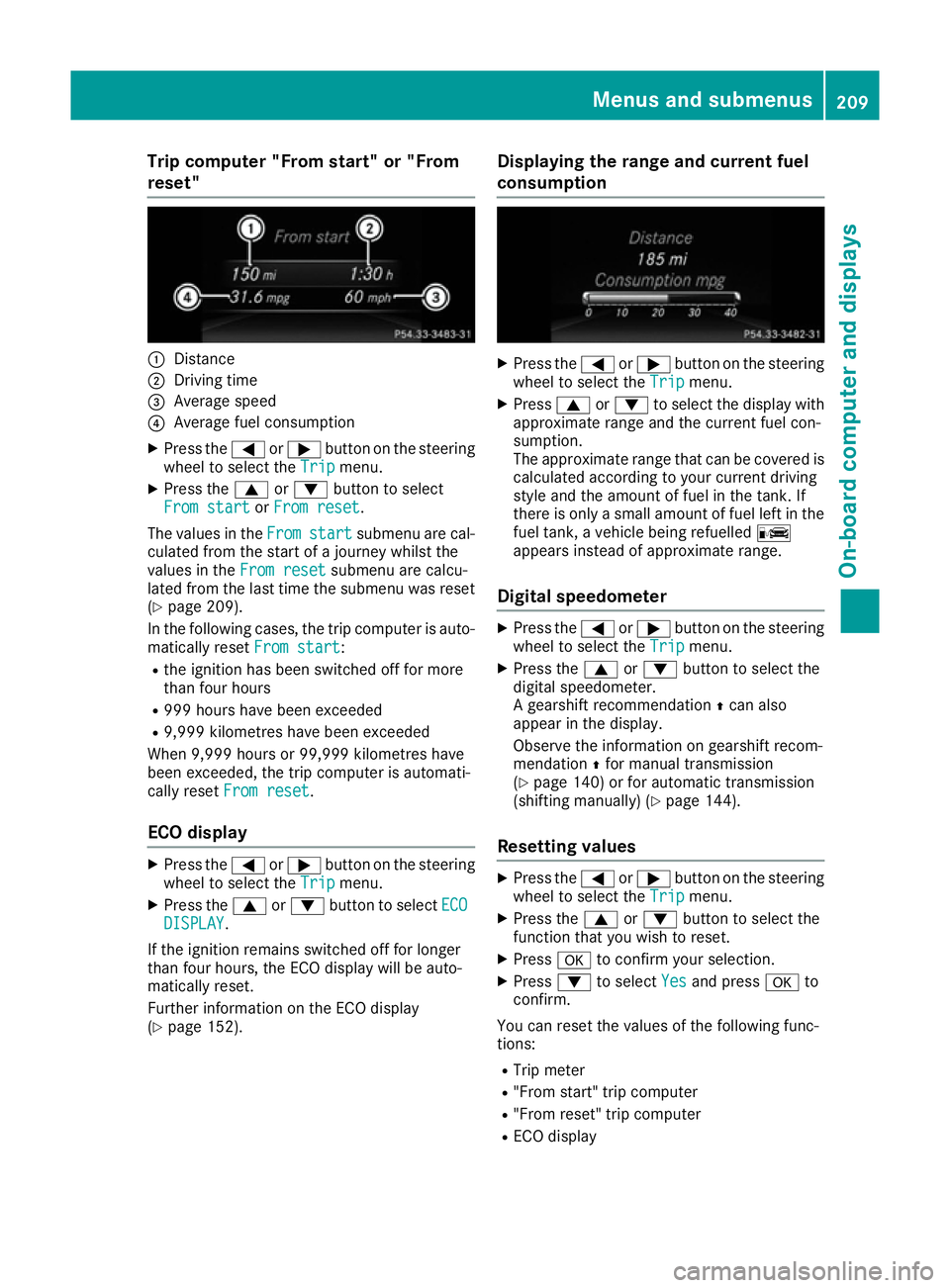
Trip computer "From start" or "From
reset" :
Distance
; Driving time
= Average speed
? Average fuel consumption
X Press the =or; button on the steering
wheel to select the Trip
Tripmenu.
X Press the 9or: button to select
From start
From start orFrom reset
From reset.
The values in the From
Fromstart
start submenu are cal-
culated from the start of a journey whilst the
values in the From reset
From reset submenu are calcu-
lated from the last time the submenu was reset
(Y page 209).
In the following cases, the trip computer is auto-
matically reset From start
From start:
R the ignition has been switched off for more
than four hours
R 999 hours have been exceeded
R 9,999 kilometres have been exceeded
When 9,999 hours or 99,999 kilometres have
been exceeded, the trip computer is automati-
cally reset From reset
From reset.
ECO display X
Press the =or; button on the steering
wheel to select the Trip
Tripmenu.
X Press the 9or: button to select ECO
ECO
DISPLAY
DISPLAY.
If the ignition remains switched off for longer
than four hours, the ECO display will be auto-
matically reset.
Further information on the ECO display
(Y page 152). Displaying the range and current fuel
consumption X
Press the =or; button on the steering
wheel to select the Trip Tripmenu.
X Press 9or: to select the display with
approximate range and the current fuel con-
sumption.
The approximate range that can be covered is calculated according to your current driving
style and the amount of fuel in the tank. If
there is only a small amount of fuel left in the
fuel tank, a vehicle being refuelled C
appears instead of approximate range.
Digital speedometer X
Press the =or; button on the steering
wheel to select the Trip Tripmenu.
X Press the 9or: button to select the
digital speedometer.
A gearshift recommendation Zcan also
appear in the display.
Observe the information on gearshift recom-
mendation Zfor manual transmission
(Y page 140) or for automatic transmission
(shifting manually) (Y page 144).
Resetting values X
Press the =or; button on the steering
wheel to select the Trip Tripmenu.
X Press the 9or: button to select the
function that you wish to reset.
X Press ato confirm your selection.
X Press :to select Yes
Yesand press ato
confirm.
You can reset the values of the following func-
tions: R Trip meter
R "From start" trip computer
R "From reset" trip computer
R ECO display Menus and submenus
209On-board computer and displays Z