2015 MERCEDES-BENZ B-Class ELECTRIC height
[x] Cancel search: heightPage 92 of 338
rials, e.g. blankets, coats, bags, seat cov-
ers, child seats or booster seats.
! Make sure that there are no objects in the
footwell under or behind the seats when
moving the seats back. There is a risk that
the seats and/or the objects could be dam-
aged.
i Further related subjects:
R cargo compartment enlargement (fold-
ing down the rear seats) (Y page 244)Adjusting the seats manually
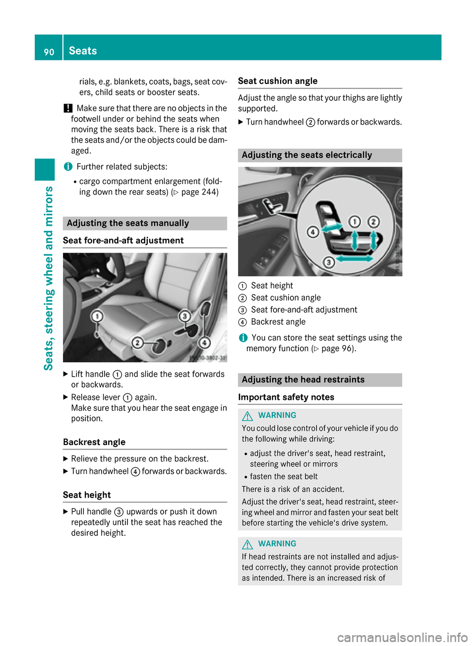
Seat fore-and-aft adjustment X
Lift handle :and slide the seat forwards
or backwards.
X Release lever :again.
Make sure that you hear the seat engage in
position.
Backrest angle X
Relieve the pressure on the backrest.
X Turn handwheel ?forwards or backwards.
Seat height X
Pull handle =upwards or push it down
repeatedly until the seat has reached the
desired height. Seat cushion angle Adjust the angle so that your thighs are lightly
supported.
X Turn handwheel ;forwards or backwards. Adjusting the seats electrically
:
Seat height
; Seat cushion angle
= Seat fore-and-aft adjustment
? Backrest angle
i You can store the seat settings using the
memory function (Y page 96). Adjusting the head restraints
Important safety notes G
WARNING
You could lose control of your vehicle if you do the following while driving:
R adjust the driver's seat, head restraint,
steering wheel or mirrors
R fasten the seat belt
There is a risk of an accident.
Adjust the driver's seat, head restraint, steer-
ing wheel and mirror and fasten your seat belt before starting the vehicle's drive system. G
WARNING
If head restraints are not installed and adjus-
ted correctly, they cannot provide protection
as intended. There is an increased risk of 90
SeatsSeats, steering wheel and mirrors
Page 93 of 338
injury in the head and neck area, e.g. in the
event of an accident or when braking.
Always drive with the head restraints instal-
led. Before driving off, make sure for every
vehicle occupant that the center of the head
restraint supports the back of the head at
about eye level.
Using the fore-and-aft adjustment, adjust the head restraint so that it is as close as possibleto your head.
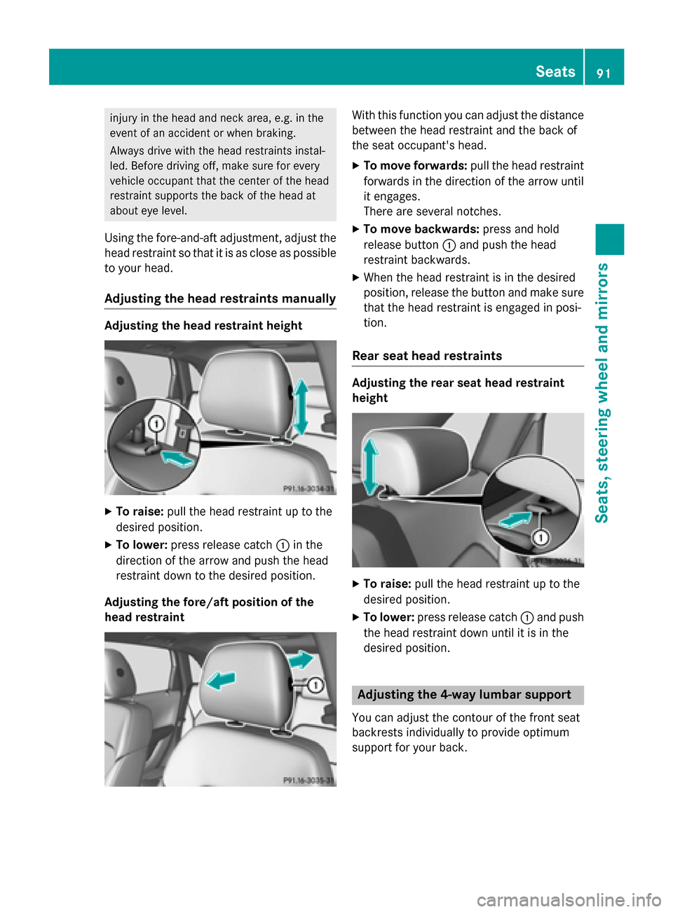
Adjusting the head restraints manually Adjusting the head restraint height
X
To raise: pull the head restraint up to the
desired position.
X To lower: press release catch :in the
direction of the arrow and push the head
restraint down to the desired position.
Adjusting the fore/aft position of the
head restraint With this function you can adjust the distance
between the head restraint and the back of
the seat occupant's head.
X To move forwards: pull the head restraint
forwards in the direction of the arrow until
it engages.
There are several notches.
X To move backwards: press and hold
release button :and push the head
restraint backwards.
X When the head restraint is in the desired
position, release the button and make sure
that the head restraint is engaged in posi-
tion.
Rear seat head restraints Adjusting the rear seat head restraint
height
X
To raise: pull the head restraint up to the
desired position.
X To lower: press release catch :and push
the head restraint down until it is in the
desired position. Adjusting the 4-way lumbar support
You can adjust the contour of the front seat
backrests individually to provide optimum
support for your back. Seats
91Seats, steering wheel and mirrors Z
Page 95 of 338
Problems with the seat heating
Problem
Possible causes/consequences and
M
MSolutions The seat heating has
switched off prema-
turely or cannot be
switched on. The on-board voltage is too low because too many electrical con-
sumers are switched on.
X Switch off electrical consumers that you do not need, such as
the rear window defroster or interior lighting.
Once the battery is sufficiently charged, the seat heating will
switch back on automatically. Steering wheel
Important safety notes
G
WARNING
You could lose control of your vehicle if you do the following while driving:
R adjust the driver's seat, head restraint,
steering wheel or mirrors
R fasten the seat belt
There is a risk of an accident.
Adjust the driver's seat, head restraint, steer-
ing wheel and mirror and fasten your seat belt before starting the vehicle's drive system. G
WARNING
Children could injure themselves if they
adjust the steering wheel. There is a risk of
injury.
When leaving the vehicle, always take the
SmartKey with you and lock the vehicle. Never leave children unsupervised in the vehicle. Adjusting the steering wheel
G
WARNING
If the steering wheel is unlocked while the
vehicle is in motion, it could change position
unexpectedly. This could cause you to lose
control of the vehicle. There is a risk of an
accident. Before starting off, make sure the steering
wheel is locked. Never unlock the steering
wheel while the vehicle is in motion.
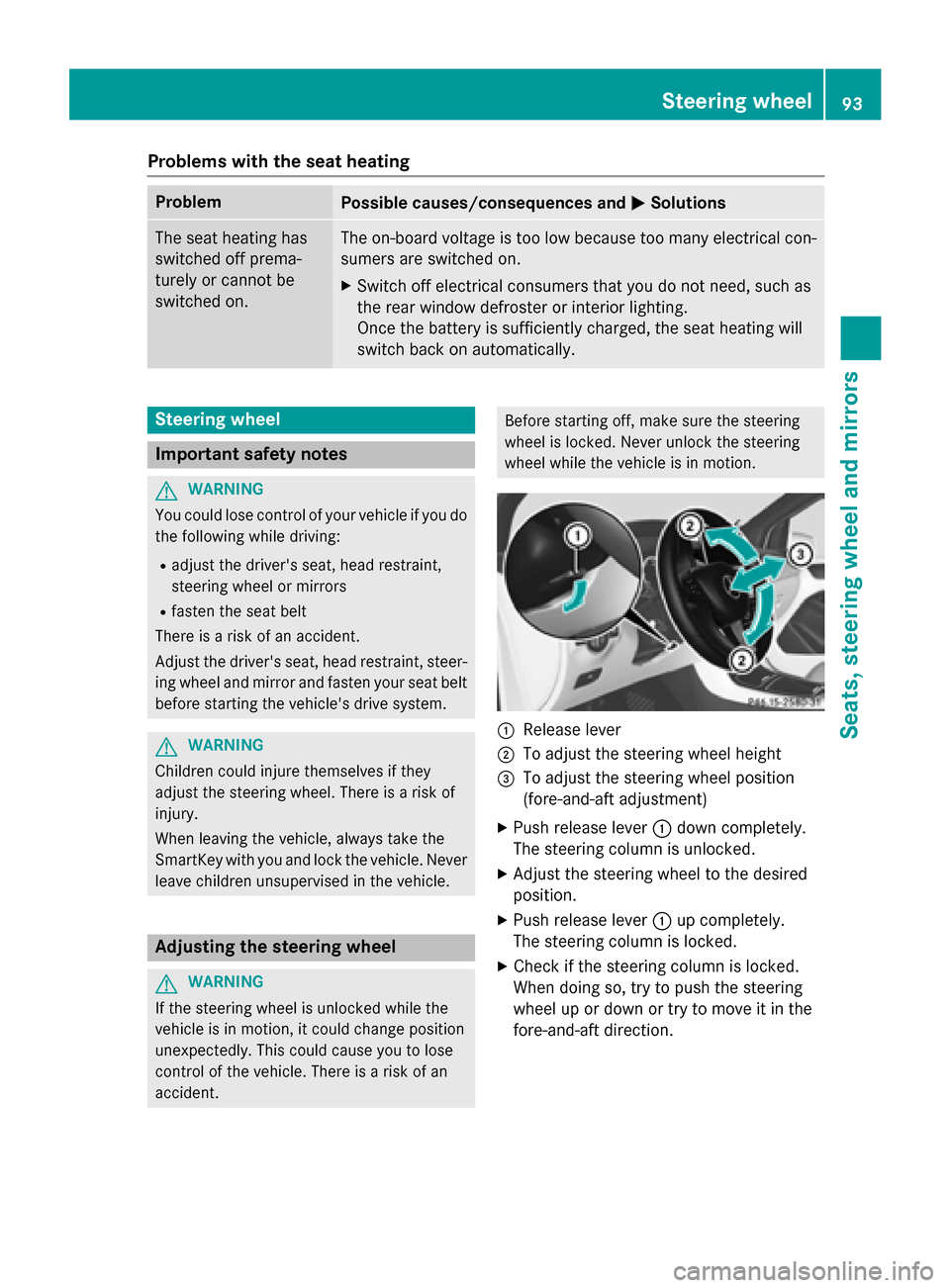
:
Release lever
; To adjust the steering wheel height
= To adjust the steering wheel position
(fore-and-aft adjustment)
X Push release lever :down completely.
The steering column is unlocked.
X Adjust the steering wheel to the desired
position.
X Push release lever :up completely.
The steering column is locked.
X Check if the steering column is locked.
When doing so, try to push the steering
wheel up or down or try to move it in the
fore-and-aft direction. Steering wheel
93Seats, steering wheel and mirrors Z
Page 171 of 338
Parking tips:
R On narrow roads, drive as close to the park-
ing space as possible.
R Parking spaces that are littered or over-
grown might be identified or measured
incorrectly.
R Parking spaces that are partially occupied
by trailer drawbars might not be identified
as such or be measured incorrectly.
R Snowfall or heavy rain may lead to a parking
space being measured inaccurately.
R Pay attention to the PARKTRONIC
(Y page 166) warning messages during the
parking procedure.
R You can intervene in the steering procedure
to correct it at any time. Active Parking
Assist will then be canceled.
R When transporting a load which protrudes
from your vehicle, you should not use
Active Parking Assist.
R Never use Active Parking Assist when snow
chains are installed.
R Make sure that the tire pressures are
always correct. This has a direct influence
on the parking characteristics of the vehi-
cle.
Use Active Parking Assist for parking spaces:
R that are parallel to the direction of travel
R that are on straight roads, not bends
R that are on the same level as the road, e.g.
not on the pavement
Detecting parking spaces Objects located above the height range of
Active Parking Assist will not be detected
when the parking space is measured. These
are not taken into account when the parking
procedure is calculated, e.g. overhanging
loads, tail sections or loading ramps of goods
vehicles. G
WARNING
If there are objects above the detection range:
R Active Park Assist may steer too early
R the vehicle may not stop in front of these
objects.
You may cause a collision as a result. There is
a risk of an accident.
If there are objects above the detection range,
stop and deactivate Active Parking Assist.
For further information on the detection
range (Y page 165).
Active Parking Assist does not support you
parking in spaces that are parallel to the
direction of travel if:
R the parking space is on a curb
R the parking space is apparently blocked,
for example by foliage or grass paving
blocks
R the range of movement is too small
R the parking space is bordered by an obsta-
cle which is not clearly defined such as a
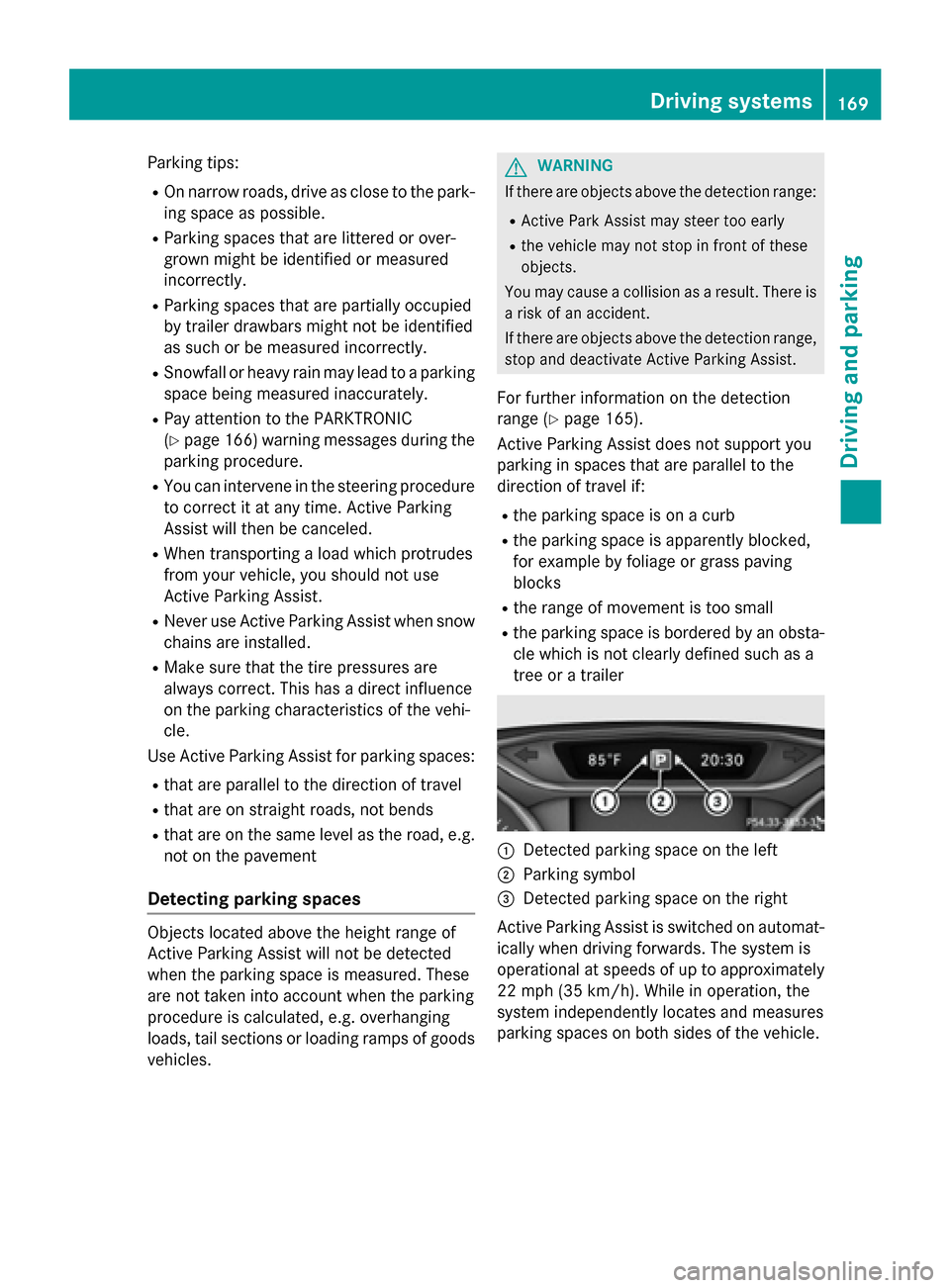
tree or a trailer :
Detected parking space on the left
; Parking symbol
= Detected parking space on the right
Active Parking Assist is switched on automat-
ically when driving forwards. The system is
operational at speeds of up to approximately 22 mph (35 km/h). While in operation, the
system independently locates and measures
parking spaces on both sides of the vehicle. Driving systems
169Driving and parking Z
Page 250 of 338
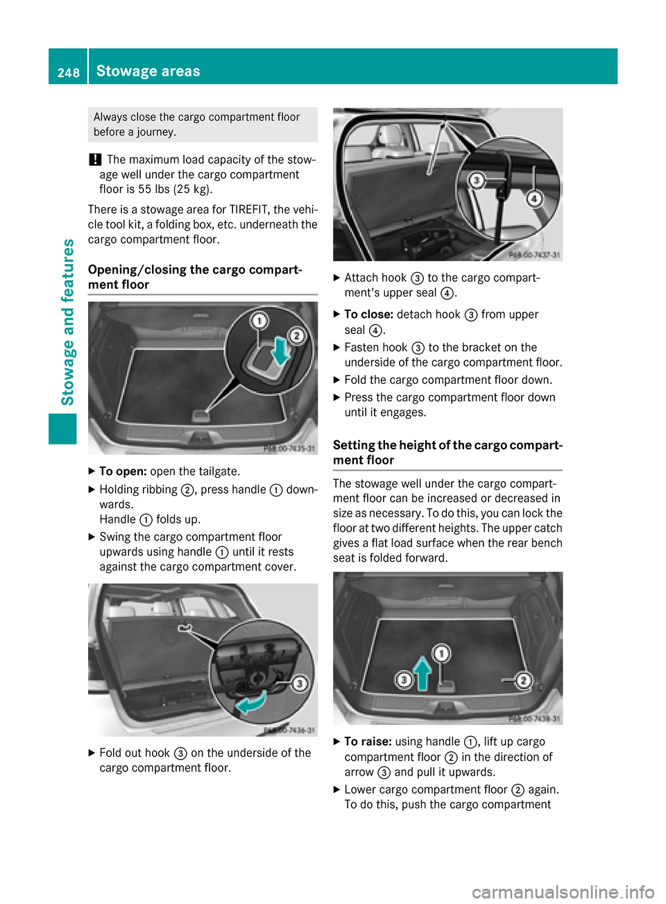
Always close the cargo compartment floor
before a journey.
! The maximum load capacity of the stow-
age well under the cargo compartment
floor is 55 lbs (25 kg).
There is a stowage area for TIREFIT, the vehi-
cle tool kit, a folding box, etc. underneath the
cargo compartment floor.
Opening/closing the cargo compart-
ment floor X
To open: open the tailgate.
X Holding ribbing ;, press handle :down-
wards.
Handle :folds up.
X Swing the cargo compartment floor
upwards using handle :until it rests
against the cargo compartment cover. X
Fold out hook =on the underside of the
cargo compartment floor. X
Attach hook =to the cargo compart-
ment's upper seal ?.
X To close: detach hook =from upper
seal ?.
X Fasten hook =to the bracket on the
underside of the cargo compartment floor.
X Fold the cargo compartment floor down.
X Press the cargo compartment floor down
until it engages.
Setting the height of the cargo compart- ment floor The stowage well under the cargo compart-
ment floor can be increased or decreased in
size as necessary. To do this, you can lock the
floor at two different heights. The upper catch gives a flat load surface when the rear benchseat is folded forward. X
To raise: using handle :, lift up cargo
compartment floor ;in the direction of
arrow =and pull it upwards.
X Lower cargo compartment floor ;again.
To do this, push the cargo compartment 248
Stowage areasSto
wage an d features
Page 271 of 338
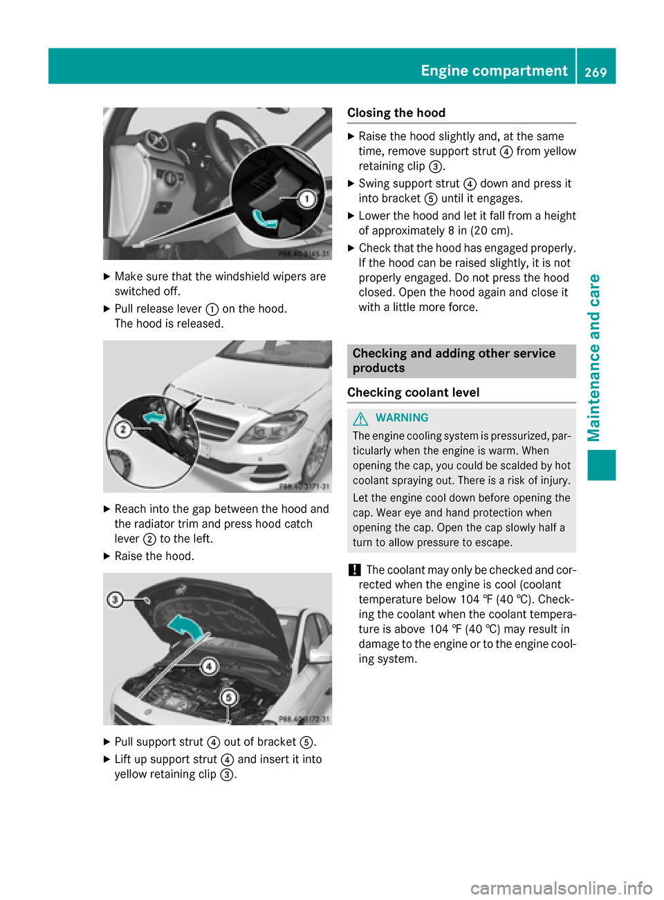
X
Make sure that the windshield wipers are
switched off.
X Pull release lever :on the hood.
The hood is released. X
Reach into the gap between the hood and
the radiator trim and press hood catch
lever ;to the left.
X Raise the hood. X
Pull support strut ?out of bracket A.
X Lift up support strut ?and insert it into
yellow retaining clip =. Closing the hood X
Raise the hood slightly and, at the same
time, remove support strut ?from yellow
retaining clip =.
X Swing support strut ?down and press it
into bracket Auntil it engages.
X Lower the hood and let it fall from a height
of approximately 8 in (20 cm).
X Check that the hood has engaged properly.
If the hood can be raised slightly, it is not
properly engaged. Do not press the hood
closed. Open the hood again and close it
with a little more force. Checking and adding other service
products
Checking coolant level G
WARNING
The engine cooling system is pressurized, par- ticularly when the engine is warm. When
opening the cap, you could be scalded by hotcoolant spraying out. There is a risk of injury.
Let the engine cool down before opening the
cap. Wear eye and hand protection when
opening the cap. Open the cap slowly half a
turn to allow pressure to escape.
! The coolant may only be checked and cor-
rected when the engine is cool (coolant
temperature below 104 ‡ (40 †). Check-
ing the coolant when the coolant tempera-
ture is above 104 ‡ (40 †) may result in
damage to the engine or to the engine cool- ing system. Engine compartment
269Maintenance and care Z
Page 317 of 338
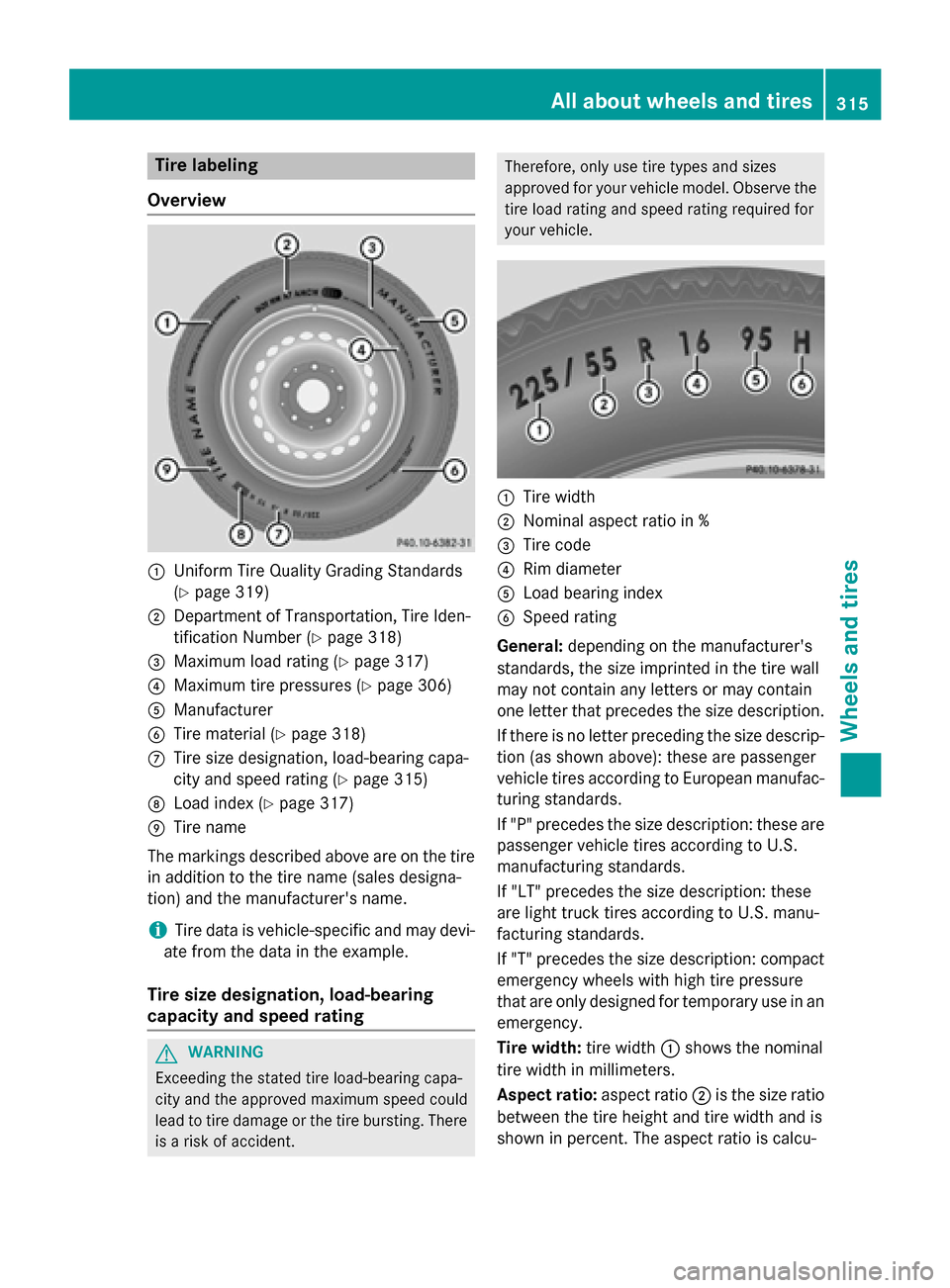
Tire labeling
Overview :
Uniform Tire Quality Grading Standards
(Y page 319)
; Department of Transportation, Tire Iden-
tification Number (Y page 318)
= Maximum load rating (Y page 317)
? Maximum tire pressures (Y page 306)
A Manufacturer
B Tire material (Y page 318)
C Tire size designation, load-bearing capa-
city and speed rating (Y page 315)
D Load index (Y page 317)
E Tire name
The markings described above are on the tire in addition to the tire name (sales designa-
tion) and the manufacturer's name.
i Tire data is vehicle-specific and may devi-
ate from the data in the example.
Tire size designation, load-bearing
capacity and speed rating G
WARNING
Exceeding the stated tire load-bearing capa-
city and the approved maximum speed could
lead to tire damage or the tire bursting. There is a risk of accident. Therefore, only use tire types and sizes
approved for your vehicle model. Observe the
tire load rating and speed rating required for
your vehicle. :
Tire width
; Nominal aspect ratio in %
= Tire code
? Rim diameter
A Load bearing index
B Speed rating
General: depending on the manufacturer's
standards, the size imprinted in the tire wall
may not contain any letters or may contain
one letter that precedes the size description.
If there is no letter preceding the size descrip-
tion (as shown above): these are passenger
vehicle tires according to European manufac-
turing standards.
If "P" precedes the size description: these are
passenger vehicle tires according to U.S.
manufacturing standards.
If "LT" precedes the size description: these
are light truck tires according to U.S. manu-
facturing standards.
If "T" precedes the size description: compact emergency wheels with high tire pressure
that are only designed for temporary use in an
emergency.
Tire width: tire width:shows the nominal
tire width in millimeters.
Aspect ratio: aspect ratio;is the size ratio
between the tire height and tire width and is
shown in percent. The aspect ratio is calcu- All about
wheels and tires
315Wheels and tires Z
Page 318 of 338
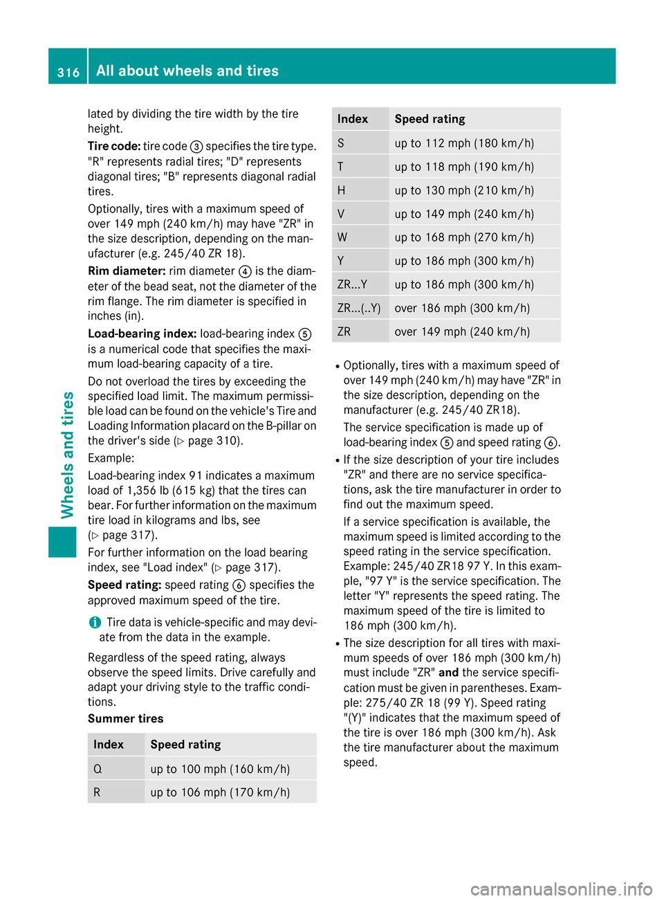
lated by dividing the tire width by the tire
height.
Tire code: tire code=specifies the tire type.
"R" represents radial tires; "D" represents
diagonal tires; "B" represents diagonal radial
tires.
Optionally, tires with a maximum speed of
over 149 mph (240 km/h) may have "ZR" in
the size description, depending on the man-
ufacturer (e.g. 245/40 ZR 18).
Rim diameter: rim diameter?is the diam-
eter of the bead seat, not the diameter of the
rim flange. The rim diameter is specified in
inches (in).
Load-bearing index: load-bearing indexA
is a numerical code that specifies the maxi-
mum load-bearing capacity of a tire.
Do not overload the tires by exceeding the
specified load limit. The maximum permissi-
ble load can be found on the vehicle's Tire and Loading Information placard on the B-pillar on
the driver's side (Y page 310).
Example:
Load-bearing index 91 indicates a maximum
load of 1,356 lb (615 kg) that the tires can
bear. For further information on the maximum
tire load in kilograms and lbs, see
(Y page 317).
For further information on the load bearing
index, see "Load index" (Y page 317).
Speed rating: speed ratingBspecifies the
approved maximum speed of the tire.
i Tire data is vehicle-specific and may devi-
ate from the data in the example.
Regardless of the speed rating, always
observe the speed limits. Drive carefully and
adapt your driving style to the traffic condi-
tions.
Summer tires Index Speed rating
Q up to 100 mph (160 km/h)
R up to 106 mph (170 km/h) Index Speed rating
S up to 112 mph (180 km/h)
T up to 118 mph (190 km/h)
H up to 130 mph (210 km/h)
V up to 149 mph (240 km/h)
W up to 168 mph (270 km/h)
Y up to 186 mph (300 km/h)
ZR...Y up to 186 mph (300 km/h)
ZR...(..Y) over 186 mph
(300 km/h) ZR over 149 mph
(240 km/h) R
Optionally, tires with a maximum speed of
over 149 mph (240 km/h) may have "ZR" in the size description, depending on the
manufacturer (e.g. 245/40 ZR18).
The service specification is made up of
load-bearing index Aand speed rating B.
R If the size description of your tire includes
"ZR" and there are no service specifica-
tions, ask the tire manufacturer in order to
find out the maximum speed.
If a service specification is available, the
maximum speed is limited according to the
speed rating in the service specification.
Example: 245/40 ZR18 97 Y.In this exam-
ple, "97 Y" is the service specification. The letter "Y" represents the speed rating. The
maximum speed of the tire is limited to
186 mph (300 km/h).
R The size description for all tires with maxi-
mum speeds of over 186 mph (300 km/h)
must include "ZR" andthe service specifi-
cation must be given in parentheses. Exam- ple: 275/40 ZR 18 (99 Y). Speed rating
"(Y)" indicates that the maximum speed of
the tire is over 186 mph (300 km/h). Ask
the tire manufacturer about the maximum
speed. 316
All about wheels and tiresWheels and tires