2015 MERCEDES-BENZ B-Class ELECTRIC clock
[x] Cancel search: clockPage 128 of 338
To activate/deactivate "Immediate pre-
entry climate control"
X Press button :in the center console.
The blue or red indicator lamp in the button
lights up or goes out.
The colors of the indicator lamps in the button have the following meanings:
Re dH eating activated
Blue Cooling activated
Yellow Pre-entry climate control at depar- ture is preselected Air vents
Important safety notes
G
WARNING
Very hot or very cold air can flow from the air vents. This could result in burns or frostbite in the immediate vicinity of the air vents. There
is a risk of injury.
Make sure that all vehicle occupants always
maintain a sufficient distance to the air out-
lets. If necessary, redirect the airflow to
another area of the vehicle interior.
In order to ensure the direct flow of fresh air
through the air vents into the vehicle interior,
please observe the following notes:
R keep the air inlet between the windshield
and the hood free of blockages, such as ice, snow or leaves.
R never cover the air vents or air intake grilles
in the vehicle interior.
i You can move the adjusters for the air
vents vertically or horizontally to set the
direction of the airflow.
i For optimal climate control in the vehicle,
open the air vents completely and set the
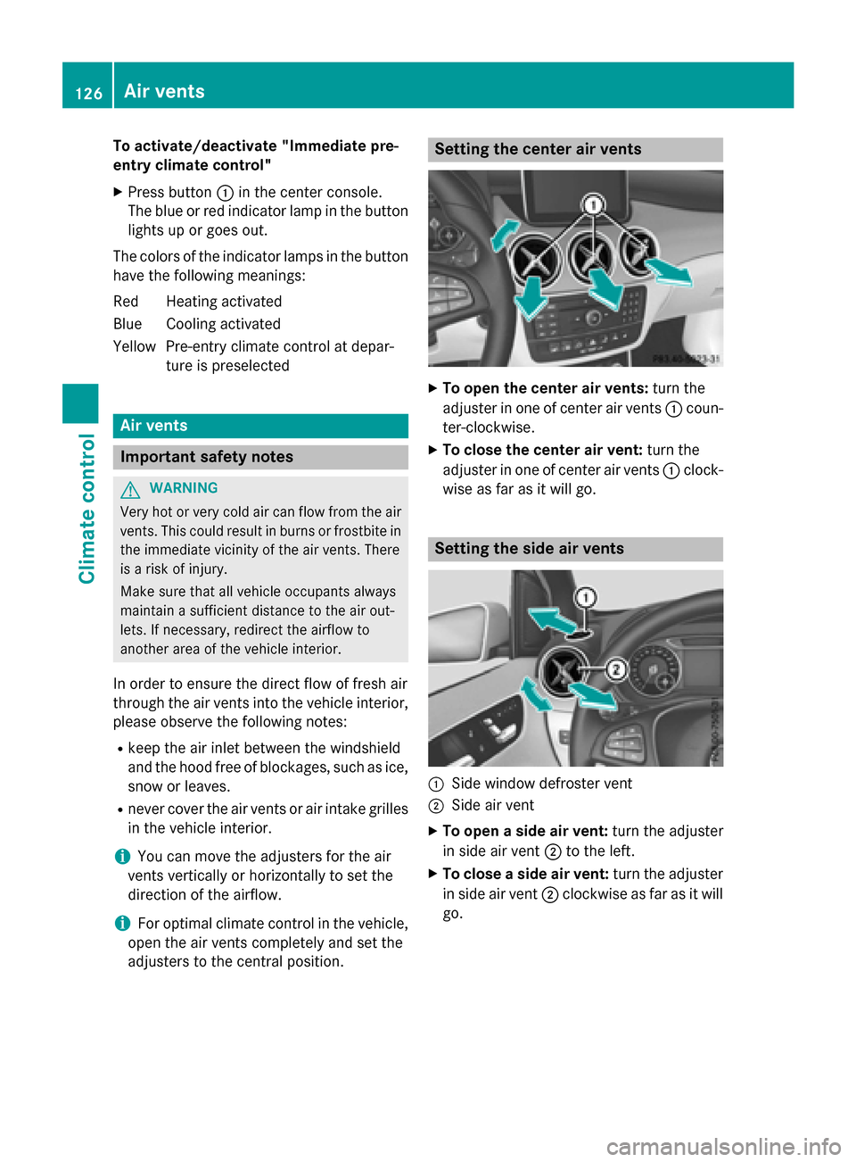
adjusters to the central position. Setting the center air vents
X
To open the center air vents: turn the
adjuster in one of center air vents :coun-
ter-clockwise.
X To close the center air vent: turn the
adjuster in one of center air vents :clock-
wise as far as it will go. Setting the side air vents
:
Side window defroster vent
; Side air vent
X To open a side air vent: turn the adjuster
in side air vent ;to the left.
X To close a side air vent: turn the adjuster
in side air vent ;clockwise as far as it will
go. 126
Air ventsClimate control
Page 184 of 338
Useful information
i This Operator's Manual describes all
models and all standard and optional equip- ment of your vehicle available at the time of
publication of the Operator's Manual.
Country-specific differences are possible.
Please note that your vehicle may not be
equipped with all features described. This
also applies to safety-related systems and
functions.
i Read the information on qualified special-
ist workshops (Y page 25). Important safety notes
G
WARNING
If you operate information systems and com-
munication equipment integrated in the vehi- cle while driving, you will be distracted from
traffic conditions. You could also lose control of the vehicle. There is a risk of an accident.
Only operate the equipment when the traffic
situation permits. If you are not sure that this
is possible, park the vehicle paying attention
to traffic conditions and operate the equip-
ment when the vehicle is stationary.
You must observe the legal requirements for
the country in which you are currently driving when operating the on-board computer. G
WARNING
If the instrument cluster has failed or mal-
functioned, you may not recognize function
restrictions in systems relevant to safety. The operating safety of your vehicle may be
impaired. There is a risk of an accident.
Drive on carefully. Have the vehicle checked
at a qualified specialist workshop immedi-
ately.
The on-board computer only shows messages
or warnings from certain systems in the mul- tifunction display. You should therefore make sure your vehicle is operating safely at all
times.
If the operating safety of your vehicle is
impaired, pull over as soon as it is safe to do
so. Contact a qualified specialist workshop.
For an overview, see the instrument panel
illustration (Y page 31). Displays and operation
Instrument cluster lighting
The light sensor in the instrument cluster
automatically controls the brightness of the
multifunction display. In daylight, the displays
in the instrument cluster are not illuminated.
The lighting in the instrument cluster, in the
displays and the controls in the vehicle inte-
rior can be adjusted using the brightness con- trol knob.
The brightness control knob is located on the
bottom left of the instrument cluster
(Y page 31).
X Turn the brightness control knob clockwise
or counter-clockwise.
If the light switch is set to Ã,Tor
L, the brightness is dependent upon
the brightness of the ambient light. READY indicator
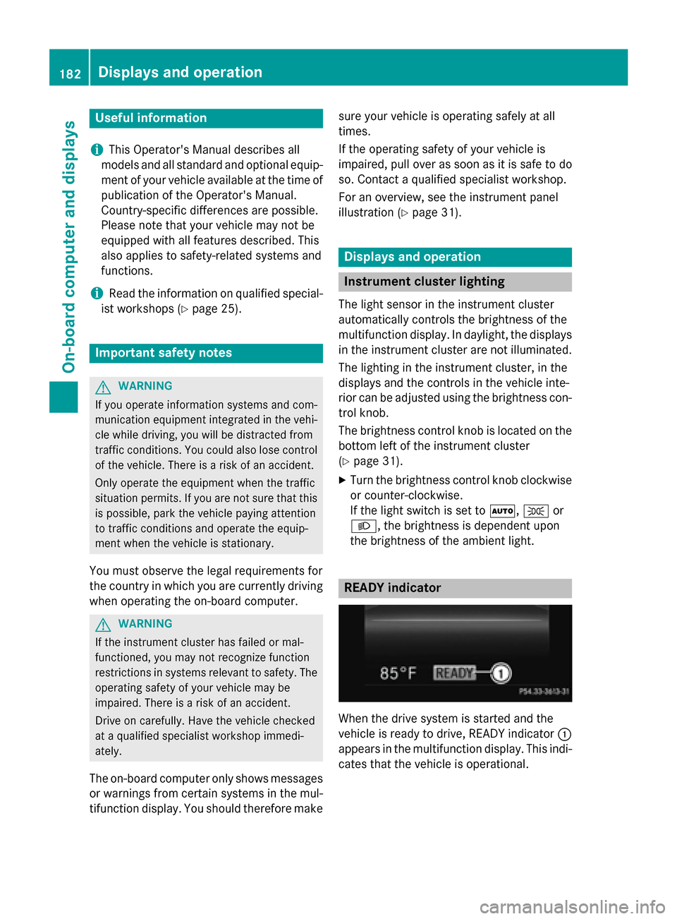
When the drive system is started and the
vehicle is ready to drive, READY indicator
:
appears in the multifunction display. This indi- cates that the vehicle is operational. 182
Displays and operationOn-board computer and displays
Page 200 of 338
![MERCEDES-BENZ B-Class ELECTRIC 2015 W246 Owners Manual Switching the additional speedometer
on/off
The
Speedometer [km/h] Speedometer [km/h] orSpeedometer
Speedometer
[mph]
[mph] function allows you to choose whether
the multifunction display in the statu MERCEDES-BENZ B-Class ELECTRIC 2015 W246 Owners Manual Switching the additional speedometer
on/off
The
Speedometer [km/h] Speedometer [km/h] orSpeedometer
Speedometer
[mph]
[mph] function allows you to choose whether
the multifunction display in the statu](/manual-img/4/3623/w960_3623-199.png)
Switching the additional speedometer
on/off
The
Speedometer [km/h] Speedometer [km/h] orSpeedometer
Speedometer
[mph]
[mph] function allows you to choose whether
the multifunction display in the status area
shows the speed in km/h km/hor inmph
mphinstead of
the outside temperature.
X Press the =or; button on the steer-
ing wheel to select the Sett.
Sett. menu.
X Press the :or9 button to select the
Instrument Cluster
Instrument Cluster submenu.
X Press ato confirm.
X Press the :or9 button to select the
Speedometer [km/h]
Speedometer [km/h] orSpeedometer
Speedometer
[mph]
[mph] function.
You will see the selected setting: On
OnorOff
Off.
X Press the abutton to save the setting.
Selecting the permanent display function You can determine whether the multifunction
display permanently shows the outside tem-
perature or your speed in km/h( USA) or mph
(Canada).
X Press the =or; button on the steer-
ing wheel to select the Sett. Sett.menu.
X Press the :or9 button to select the
Instrument Cluster
Instrument Cluster submenu.
X Press ato confirm.
X Press the :or9 button to select the
Permanent Display:
Permanent Display: function.
You will see the selected setting: Outside
Outside
Temperature Temperature orSpeedometer [km/h] Speedometer [km/h]/
Speedometer [mph]
Speedometer [mph].
X Press the abutton to save the setting.
i The speed is highlighted in km/h or in
mph conversely to your speedometer.
Lights Switching the daytime running lamps on/
off
X Press the =or; button on the steer-
ing wheel to select the Sett.
Sett.menu.
X Press the :or9 button to select the
Lights
Lights submenu. X
Press ato confirm.
X Press the :or9 button to select the
Daytime Running Lights
Daytime Running Lights function.
If the Daytime Running Lights
Daytime Running Lights function
has been switched on, the cone of light and
the W symbol in the multifunction dis-
play are shown in orange.
X Press the abutton to save the setting.
Further information on daytime running lights (Y page 100).
Vehicle Activating/deactivating the automatic
door locking mechanism
X Press the =or; button on the steer-
ing wheel to select the Sett. Sett.menu.
X Press the :or9 button to select the
Vehicle
Vehicle submenu.
X Press ato confirm.
X Press the :or9 button to select the
Automatic Door Lock
Automatic Door Lock function.
When the Automatic
Automatic Door
DoorLock
Lockfunction
is activated, the vehicle doors are displayed in orange in the multifunction display.
X Press the abutton to save the setting.
If you activate the Automatic Door Lock
Automatic Door Lock
function, the vehicle is centrally locked above
a speed of around 9 mph (15 km/h).
For further information on the automatic lock- ing feature, see (Y page 80).
Activating/deactivating the acoustic
locking verification signal
If you switch on the Acoustic AcousticLock Lockfunction,
an acoustic signal sounds when you lock the
vehicle.
X Press the =or; button on the steer-
ing wheel to select the Sett.
Sett.menu.
X Press the :or9 button to select the
Vehicle
Vehicle submenu.
X Press ato confirm. 198
Menus and submenusOn-board computer and displays
Page 272 of 338
X
Park the vehicle on a level surface.
Only check the coolant level when the vehi-
cle is on a level surface and the drive sys-
tem has cooled down.
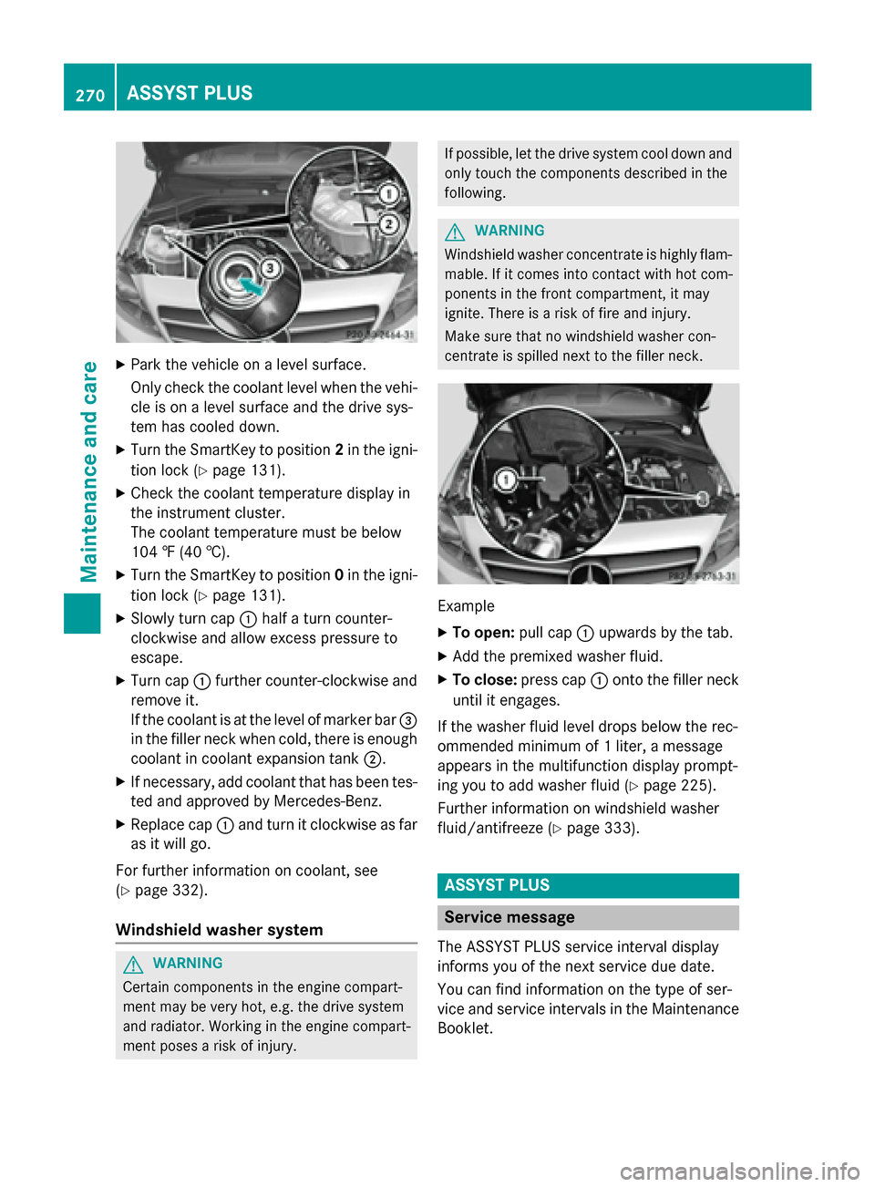
X Turn the SmartKey to position 2in the igni-
tion lock (Y page 131).
X Check the coolant temperature display in
the instrument cluster.
The coolant temperature must be below
104 ‡ (40 †).
X Turn the SmartKey to position 0in the igni-
tion lock (Y page 131).
X Slowly turn cap :half a turn counter-
clockwise and allow excess pressure to
escape.
X Turn cap :further counter-clockwise and
remove it.
If the coolant is at the level of marker bar =
in the filler neck when cold, there is enough coolant in coolant expansion tank ;.
X If necessary, add coolant that has been tes-
ted and approved by Mercedes-Benz.
X Replace cap :and turn it clockwise as far
as it will go.
For further information on coolant, see
(Y page 332).
Windshield washer system G
WARNING
Certain components in the engine compart-
ment may be very hot, e.g. the drive system
and radiator. Working in the engine compart-
ment poses a risk of injury. If possible, let the drive system cool down and
only touch the components described in the
following. G
WARNING
Windshield washer concentrate is highly flam- mable. If it comes into contact with hot com-
ponents in the front compartment, it may
ignite. There is a risk of fire and injury.
Make sure that no windshield washer con-
centrate is spilled next to the filler neck. Example
X To open: pull cap:upwards by the tab.
X Add the premixed washer fluid.
X To close: press cap :onto the filler neck
until it engages.
If the washer fluid level drops below the rec-
ommended minimum of 1 liter, a message
appears in the multifunction display prompt-
ing you to add washer fluid (Y page 225).
Further information on windshield washer
fluid/antifreeze (Y page 333). ASSYST PLUS
Service message
The ASSYST PLUS service interval display
informs you of the next service due date.
You can find information on the type of ser-
vice and service intervals in the Maintenance
Booklet. 270
ASSYST PLUSMaintenance and care
Page 289 of 338
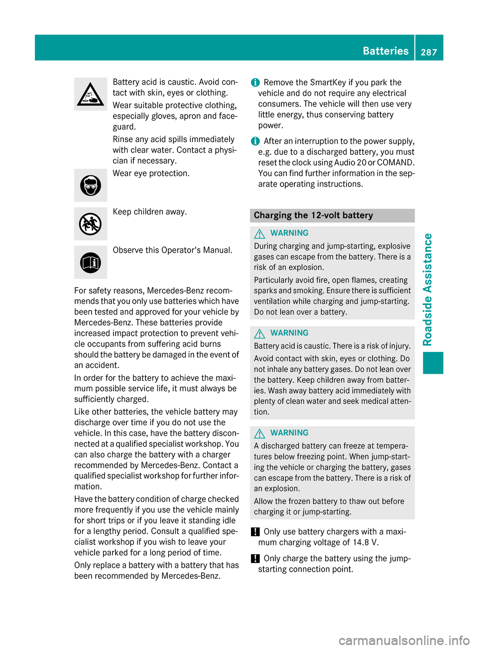
Battery acid is caustic. Avoid con-
tact with skin, eyes or clothing.
Wear suitable protective clothing,
especially gloves, apron and face-
guard.
Rinse any acid spills immediately
with clear water. Contact a physi-
cian if necessary.
Wear eye protection.
Keep children away.
Observe this Operator's Manual.
For safety reasons, Mercedes-Benz recom-
mends that you only use batteries which have been tested and approved for your vehicle by
Mercedes-Benz. These batteries provide
increased impact protection to prevent vehi-
cle occupants from suffering acid burns
should the battery be damaged in the event of
an accident.
In order for the battery to achieve the maxi-
mum possible service life, it must always be
sufficiently charged.
Like other batteries, the vehicle battery may
discharge over time if you do not use the
vehicle. In this case, have the battery discon- nected at a qualified specialist workshop. You
can also charge the battery with a charger
recommended by Mercedes-Benz. Contact a
qualified specialist workshop for further infor- mation.
Have the battery condition of charge checked
more frequently if you use the vehicle mainly
for short trips or if you leave it standing idle
for a lengthy period. Consult a qualified spe-
cialist workshop if you wish to leave your
vehicle parked for a long period of time.
Only replace a battery with a battery that has been recommended by Mercedes-Benz. i
Remove the SmartKey if you park the
vehicle and do not require any electrical
consumers. The vehicle will then use very
little energy, thus conserving battery
power.
i After an interruption to the power supply,
e.g. due to a discharged battery, you must
reset the clock using Audio 20 or COMAND. You can find further information in the sep-
arate operating instructions. Charging the 12‑
volt battery G
WARNING
During charging and jump-starting, explosive
gases can escape from the battery. There is a risk of an explosion.
Particularly avoid fire, open flames, creating
sparks and smoking. Ensure there is sufficient
ventilation while charging and jump-starting.
Do not lean over a battery. G
WARNING
Battery acid is caustic. There is a risk of injury. Avoid contact with skin, eyes or clothing. Do
not inhale any battery gases. Do not lean over
the battery. Keep children away from batter-
ies. Wash away battery acid immediately with
plenty of clean water and seek medical atten- tion. G
WARNING
A discharged battery can freeze at tempera-
tures below freezing point. When jump-start-
ing the vehicle or charging the battery, gases can escape from the battery. There is a risk of
an explosion.
Allow the frozen battery to thaw out before
charging it or jump-starting.
! Only use battery chargers with a maxi-
mum charging voltage of 14.8 V.
! Only
charge the battery using the jump-
starting connection point. Batteries
287Roadside Assistance Z
Page 296 of 338
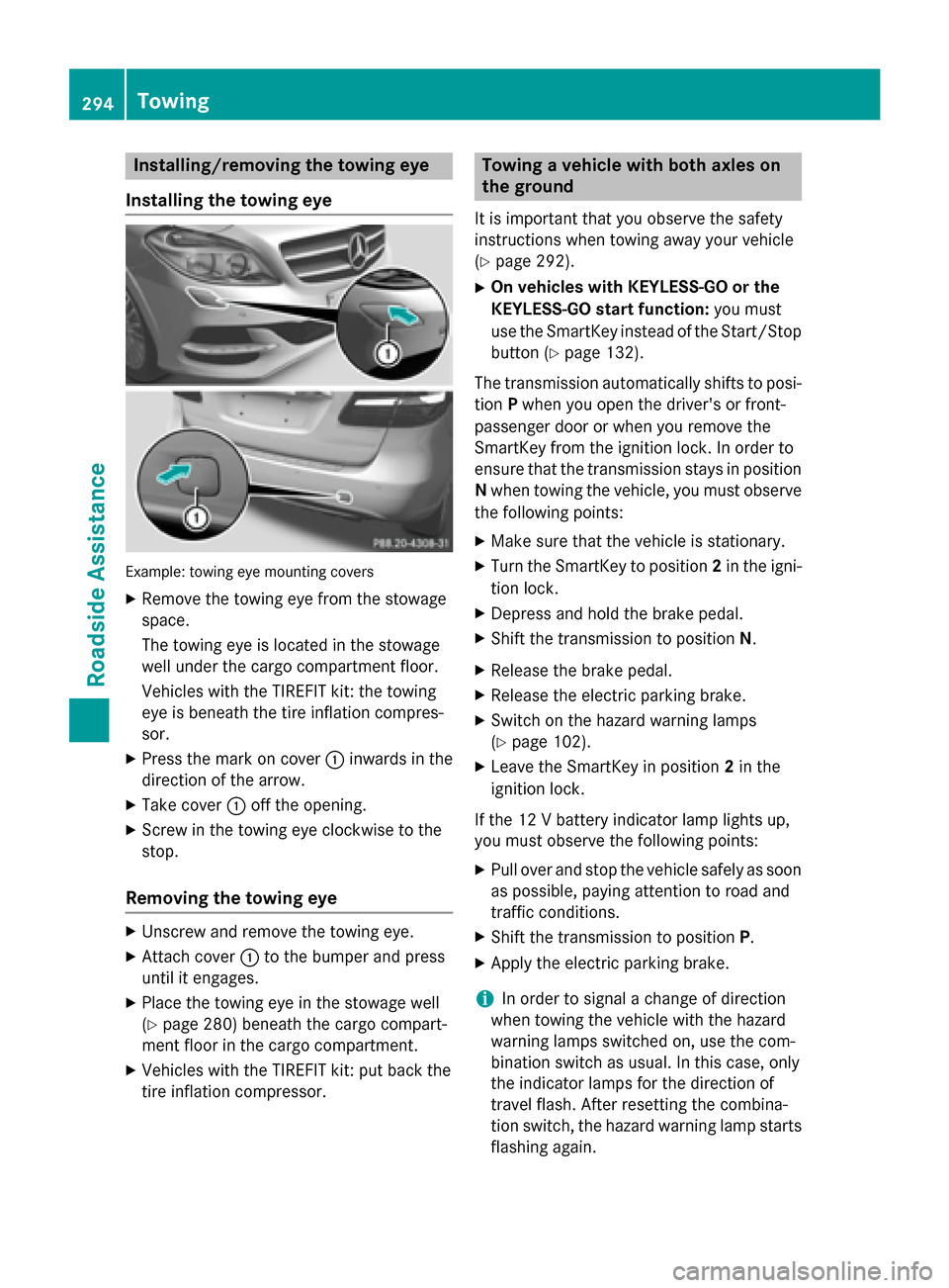
Installing/removing the towing eye
Installing the towing eye Example: towing eye mounting covers
X Remove the towing eye from the stowage
space.
The towing eye is located in the stowage
well under the cargo compartment floor.
Vehicles with the TIREFIT kit: the towing
eye is beneath the tire inflation compres-
sor.
X Press the mark on cover :inwards in the
direction of the arrow.
X Take cover :off the opening.
X Screw in the towing eye clockwise to the
stop.
Removing the towing eye X
Unscrew and remove the towing eye.
X Attach cover :to the bumper and press
until it engages.
X Place the towing eye in the stowage well
(Y page 280) beneath the cargo compart-
ment floor in the cargo compartment.
X Vehicles with the TIREFIT kit: put back the
tire inflation compressor. Towing a vehicle with both axles on
the ground
It is important that you observe the safety
instructions when towing away your vehicle
(Y page 292).
X On vehicles with KEYLESS-GO or the
KEYLESS-GO start function: you must
use the SmartKey instead of the Start/Stop
button (Y page 132).
The transmission automatically shifts to posi- tion Pwhen you open the driver's or front-
passenger door or when you remove the
SmartKey from the ignition lock. In order to
ensure that the transmission stays in position N when towing the vehicle, you must observe
the following points:
X Make sure that the vehicle is stationary.
X Turn the SmartKey to position 2in the igni-
tion lock.
X Depress and hold the brake pedal.
X Shift the transmission to position N.
X Release the brake pedal.
X Release the electric parking brake.
X Switch on the hazard warning lamps
(Y page 102).
X Leave the SmartKey in position 2in the
ignition lock.
If the 12 V battery indicator lamp lights up,
you must observe the following points:
X Pull over and stop the vehicle safely as soon
as possible, paying attention to road and
traffic conditions.
X Shift the transmission to position P.
X Apply the electric parking brake.
i In order to signal a change of direction
when towing the vehicle with the hazard
warning lamps switched on, use the com-
bination switch as usual. In this case, only
the indicator lamps for the direction of
travel flash. After resetting the combina-
tion switch, the hazard warning lamp starts
flashing again. 294
TowingRoadside Assistance