2015 MERCEDES-BENZ B-Class ELECTRIC fuse
[x] Cancel search: fusePage 11 of 338
ESP
®
(Electronic Stability Pro-
gram)
Activating/deactivating (on-
board computer) ............................ 194
Characteristics ................................ .67
Deactivating/activating (notes )....... 67
Display message ............................ 201
ETS .................................................. 66
Function/note s................................ 66
General notes .................................. 66
Important safety information ........... 66
Warning lamp ................................. 233
ETS (Electronic Traction System) ....... 66
Exhaustive discharging (high-volt-
age battery) ....................................... 288
Exterior lighting
Cleaning ......................................... 275
see Lights
Exterior mirrors
Adjusting ......................................... 94
Dipping (automatic) ......................... 95
Out of position (troubleshooting) ..... 94
Storing settings (memory func-
tion) ................................................. 97
Storing the parking position ............. 95
Eyeglasses compartment ................. 241F
Flat tire MOExtended tire s.......................... 281
Preparing the vehicle ..................... 280
TIREFIT kit ...................................... 282
Floormats ........................................... 265
Folding table ...................................... 242
Front-passenger seat
Folding the backrest forward/
back ............................................... 243
Fuses
Allocation chart ............................. 297
Before changing ............................. 296
Fuse box in the engine compart-
ment .............................................. 296
Fuse box in the front-passenger
footwell .......................................... 297
Important safety notes .................. 296 G
Garage door opener Clearing the memory ..................... 264
General notes ................................ 261
Important safety notes .................. 261
Opening/closing the garage doo r..2 64
Programming (button in the rear-
view mirror) ................................... 262
Synchronizing the rolling code ....... 262
Generated electrical energy (Audio
20) ...................................................... 142
Genuine parts ...................................... 19
Glove box .......................................... .241 H
Hazard warning lamps Display message ............................ 226
Switching on/off ........................... 102
Head restraints
Adjusting ......................................... 90
Adjusting (manually) ........................ 91
Adjusting (rear) ................................ 91
Headlamps
Fogging up ..................................... 104
see Automatic headlamp mode
Heating
see Climate control
High beam flasher ............................. 102
High voltage
see Safety notes
High-beam headlamps
Adaptive Highbeam Assist ............. 103
Changing bulb s.............................. 108
Display message ............................ 215
Switching on/of f........................... 102
High-voltage battery
Battery care ................................... 145
Charging (charging station) ............ 149
Charging (mains socket) ................ 146
Charging cable warming ................ 145
Cruise range .................................. 142
Discharged battery ........................ 141
Display message ............................ 218
Displaying energy consumption
(on-board computer) ...................... 188 Index
9
Page 147 of 338
X
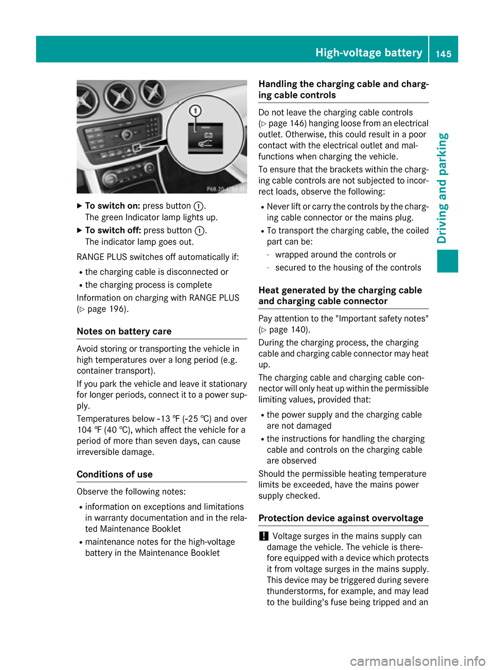
To switch on: press button:.
The green Indicator lamp lights up.
X To switch off: press button:.
The indicator lamp goes out.
RANGE PLUS switches off automatically if: R the charging cable is disconnected or
R the charging process is complete
Information on charging with RANGE PLUS
(Y page 196).
Notes on battery care Avoid storing or transporting the vehicle in
high temperatures over a long period (e.g.
container transport).
If you park the vehicle and leave it stationary
for longer periods, connect it to a power sup-
ply.
Temperatures below Ò13‡(Ò25 †) and over
104 ‡ (40 †), which affect the vehicle for a
period of more than seven days, can cause
irreversible damage.
Conditions of use Observe the following notes:
R information on exceptions and limitations
in warranty documentation and in the rela-
ted Maintenance Booklet
R maintenance notes for the high-voltage
battery in the Maintenance Booklet Handling the charging cable and charg-
ing cable controls Do not leave the charging cable controls
(Y page 146) hanging loose from an electrical
outlet. Otherwise, this could result in a poor
contact with the electrical outlet and mal-
functions when charging the vehicle.
To ensure that the brackets within the charg- ing cable controls are not subjected to incor-
rect loads, observe the following:
R Never lift or carry the controls by the charg-
ing cable connector or the mains plug.
R To transport the charging cable, the coiled
part can be:
- wrapped around the controls or
- secured to the housing of the controls
Heat generated by the charging cable
and charging cable connector Pay attention to the "Important safety notes"
(Y page 140).
During the charging process, the charging
cable and charging cable connector may heat
up.
The charging cable and charging cable con-
nector will only heat up within the permissible
limiting values, provided that:
R the power supply and the charging cable
are not damaged
R the instructions for handling the charging
cable and controls on the charging cable
are observed
Should the permissible heating temperature
limits be exceeded, have the mains power
supply checked.
Protection device against overvoltage !
Voltage surges in the mains supply can
damage the vehicle. The vehicle is there-
fore equipped with a device which protects
it from voltage surges in the mains supply.
This device may be triggered during severe
thunderstorms, for example, and may lead
to the building's fuse being tripped and an High-voltage battery
145Driving and parking Z
Page 148 of 338
interruption in the power supply. These
functions protect the vehicle. After the
building fuse is switched on again, the
charging process resumes automatically.
Following an interruption in the power sup- ply without tripping of the building's fuse, it
may take up to 15 minutes for charging to
resume automatically.
Switch on the building's fuse again after the
protection device against overvoltage has
been triggered. Otherwise, the charging proc-
ess cannot be continued. The high-voltage
battery will not be charged and you may not
be able to drive the vehicle.
If other devices are protected by the same
protective device, these are switched off as
well when the protective device is triggered.
Ensure that these other devices are still
operational after reactivating the protection
device. Charging the high-voltage battery via
the electrical outlet
Charging cable Important safety notes
! Only use the charging cable to charge the
high-voltage battery. Do not use the charg-
ing cable for other purposes. It may other-
wise be damaged.
The vehicle is supplied with a single-phase
12 A charging cable. Only use the charging
cable included with the vehicle, which has
been approved for vehicle use.
Pay attention to the "Important safety notes"
(Y page 140).
If you use the supplied 12 Acharging cable to
charge a high-voltage battery:
R the charge time increases considerably
R electrical consumption increases consider-
ably
Where possible, charge the high-voltage bat-
tery at a charging station (Y page 149). Onlythen can certified electrical energy consump-
tion levels be reached.
i The charging process can vary depending
on the charging station. Therefore, always
observe the local information.
Stowing the charging cable
The charging cable can be stowed in a bag in the trunk of the vehicle. To do so, the bag
must be secured to the cargo tie-down rings
using the retaining strap provided.
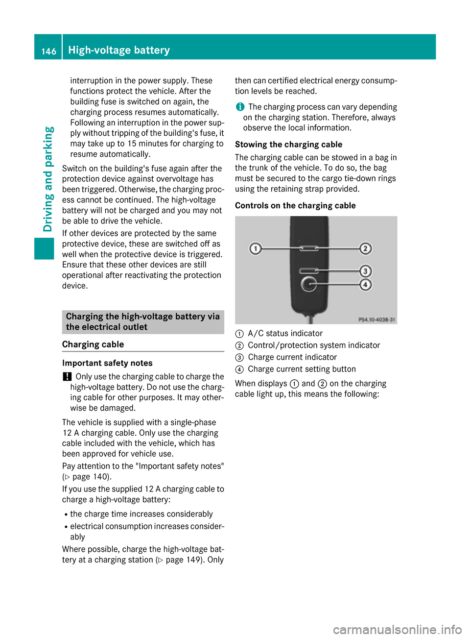
Controls on the charging cable :
A/C status indicator
; Control/protection system indicator
= Charge current indicator
? Charge current setting button
When displays :and ;on the charging
cable light up, this means the following: 146
High-voltage batteryDriving and parking
Page 149 of 338
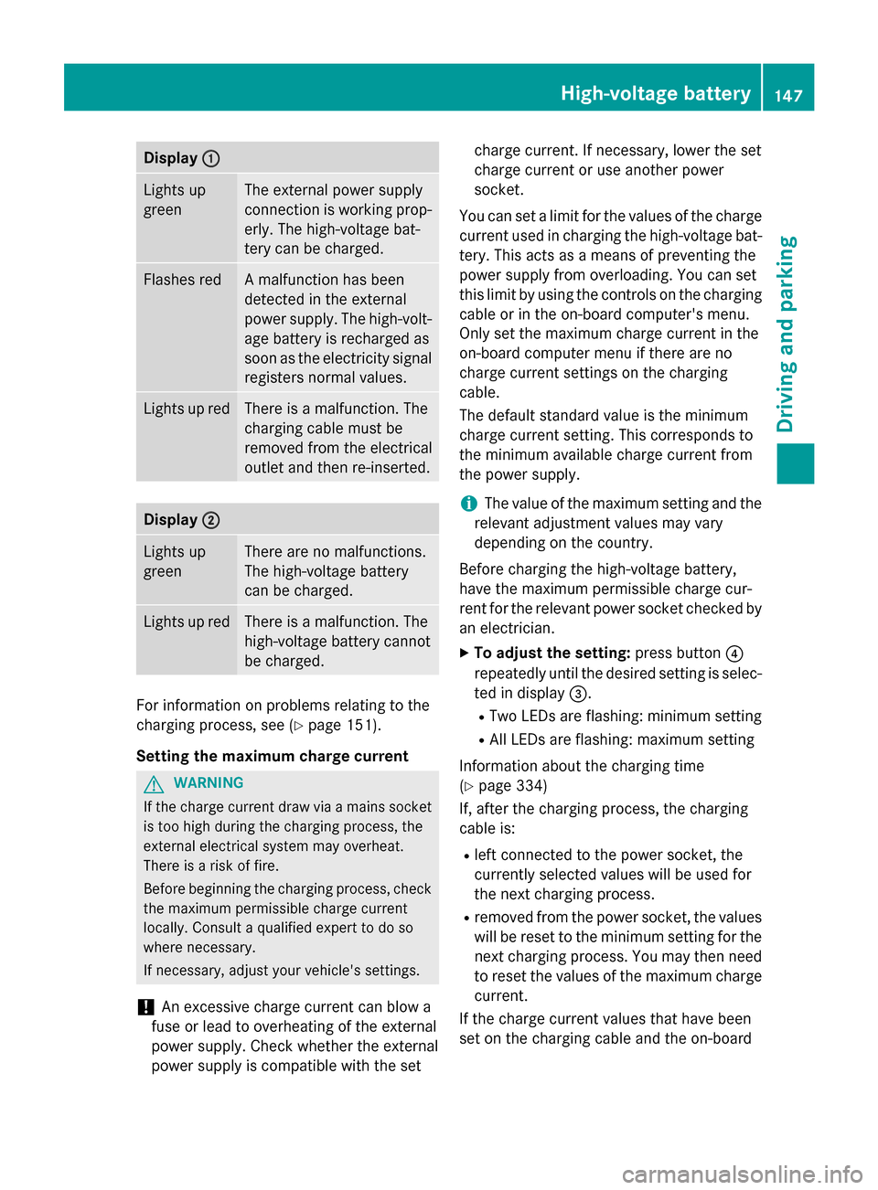
Display
:
: Lights up
green The external power supply
connection is working prop-
erly. The high-voltage bat-
tery can be charged. Flashes red A malfunction has been
detected in the external
power supply. The high-volt-
age battery is recharged as
soon as the electricity signal
registers normal values. Lights up red There is a malfunction. The
charging cable must be
removed from the electrical
outlet and then re-inserted.
Display
; ; Lights up
green There are no malfunctions.
The high-voltage battery
can be charged.
Lights up red There is a malfunction. The
high-voltage battery cannot
be charged. For information on problems relating to the
charging process, see (Y
page 151).
Setting the maximum charge current G
WARNING
If the charge current draw via a mains socket is too high during the charging process, the
external electrical system may overheat.
There is a risk of fire.
Before beginning the charging process, check the maximum permissible charge current
locally. Consult a qualified expert to do so
where necessary.
If necessary, adjust your vehicle's settings.
! An excessive charge current can blow a
fuse or lead to overheating of the external
power supply. Check whether the external
power supply is compatible with the set charge current. If necessary, lower the set
charge current or use another power
socket.
You can set a limit for the values of the charge current used in charging the high-voltage bat-
tery. This acts as a means of preventing the
power supply from overloading. You can set
this limit by using the controls on the charging
cable or in the on-board computer's menu.
Only set the maximum charge current in the
on-board computer menu if there are no
charge current settings on the charging
cable.
The default standard value is the minimum
charge current setting. This corresponds to
the minimum available charge current from
the power supply.
i The value of the maximum setting and the
relevant adjustment values may vary
depending on the country.
Before charging the high-voltage battery,
have the maximum permissible charge cur-
rent for the relevant power socket checked by
an electrician.
X To adjust the setting: press button?
repeatedly until the desired setting is selec- ted in display =.
R Two LEDs are flashing: minimum setting
R All LEDs are flashing: maximum setting
Information about the charging time
(Y page 334)
If, after the charging process, the charging
cable is:
R left connected to the power socket, the
currently selected values will be used for
the next charging process.
R removed from the power socket, the values
will be reset to the minimum setting for the next charging process. You may then need
to reset the values of the maximum charge current.
If the charge current values that have been
set on the charging cable and the on-board High-voltage batte
ry
147Driving an d parking Z
Page 166 of 338
The vehicle is kept stationary without the
driver having to depress the brake pedal.
The braking effect is canceled and the HOLD
function deactivated when you depress the
accelerator pedal to pull away.
Important safety notes G
WARNING
When leaving the vehicle, it can still roll away despite being braked by the HOLD function if:
R there is a malfunction in the system or in
the voltage supply.
R the HOLD function has been deactivated by
pressing the accelerator pedal or the brake
pedal, e.g. by a vehicle occupant.
R the electrical system in the engine com-
partment, the battery or the fuses have
been tampered with.
R the battery is disconnected
There is a risk of an accident.
If you wish to exit the vehicle, always turn off the HOLD function and secure the vehicle
against rolling away.
! If the HOLD function is activated, the vehi-
cle brakes automatically in certain situa-
tions.
To prevent damage to the vehicle, deacti-
vate the HOLD function in the following or
other similar situations:
R when towing the vehicle
R in the car wash
Deactivating the HOLD function
(Y page 164).
Activation conditions You can activate the HOLD function if:
R the vehicle is stationary
R the engine is running or if it has been auto-
matically switched off by the ECO start/
stop function
R the driver's door is closed or your seat belt
is fastened R
the electric parking brake is released
R the transmission is in position D,Ror N
Activating the HOLD function X
Make sure that the activation conditions
are met.
X Depress the brake pedal.
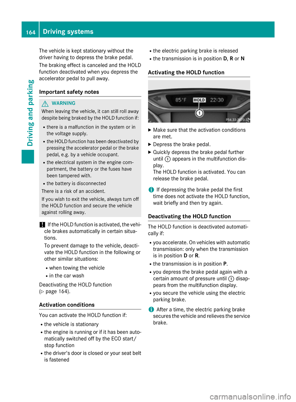
X Quickly depress the brake pedal further
until :appears in the multifunction dis-
play.
The HOLD function is activated. You can
release the brake pedal.
i If depressing the brake pedal the first
time does not activate the HOLD function,
wait briefly and then try again.
Deactivating the HOLD function The HOLD function is deactivated automati-
cally if:
R you accelerate. On vehicles with automatic
transmission: only when the transmission
is in position Dor R.
R the transmission is in position P.
R you depress the brake pedal again with a
certain amount of pressure until :disap-
pears from the multifunction display.
R you secure the vehicle using the electric
parking brake.
i After a time, the electric parking brake
secures the vehicle and relieves the service
brake. 164
Driving systemsDriving and parking
Page 281 of 338
Useful information
............................280
Where will I find...? ...........................280
Flat tire .............................................. 280
Batteries ............................................ 285
Jump-starting .................................... 290
Towing ............................................... 292
Fuses .................................................. 296 279Roadside Assistance
Page 298 of 338
X
Turn the SmartKey to position 0in the igni-
tion lock and remove it.
X Secure the vehicle.
The towing eye can be used to pull the vehicle
onto a trailer or transporter for transporting
purposes. Fuses
Important safety notes
G
WARNING
If you manipulate or bridge a faulty fuse or if
you replace it with a fuse with a higher amper- age, the electric cables could be overloaded.
This could result in a fire. There is a risk of an
accident and injury.
Always replace faulty fuses with the specified
new fuses having the correct amperage.
Blown fuses must be replaced with fuses of
the same rating, which you can recognize by
the color and value. The fuse ratings are listed in the fuse allocation chart.
If a newly inserted fuse also blows, have the
cause traced and rectified at a qualified spe-
cialist workshop, e.g. an authorized
Mercedes-Benz Center.
! Only use fuses that have been approved
for Mercedes-Benz vehicles and which
have the correct fuse rating for the system
concerned. Only use fuses marked with an "S". Otherwise, components or systems
could be damaged.
The fuses in your vehicle serve to close down faulty circuits. If a fuse blows, all the compo-
nents on the circuit and their functions stop
operating.
Blown fuses must be replaced with fuses of
the same rating, which you can recognize by
the color and value. The fuse ratings are listed in the fuse allocation chart.
If a newly inserted fuse also blows, have the
cause traced and rectified at a qualified spe- cialist workshop, e.g. an authorized
Mercedes-Benz Center. Before changing a fuse
X Secure the vehicle against rolling away
(Y page 153).
X Switch off all electrical consumers.
X Vehicles without KEYLESS-GO: remove
the SmartKey from the ignition lock.
X Vehicles with KEYLESS-GO start-func-
tion or KEYLESS-GO: open the driver's
door.
The on-board electronics now have status
0. This is the same as the SmartKey having
been removed.
The fuses are located in various fuse boxes:
R Fuse box in the engine compartment on the
left-hand side of the vehicle, when viewed
in the direction of travel
R Fuse box in the front-passenger footwell
The fuse allocation chart is on the fuse box in
the front-passenger footwell (Y page 297). Fuse box in the engine compartment
G
WARNING
When the hood is open and the windshield
wipers are set in motion, you can be injured by the wiper linkage. There is a risk of injury.
Always switch off the windshield wipers and
the ignition before opening the hood.
! Make sure that no moisture can enter the
fuse box when the cover is open.
! When closing the cover, make sure that it
is lying correctly on the fuse box. Moisture
seeping in or dirt could otherwise impair
the operation of the fuses. 296
FusesRoadside Assistance
Page 299 of 338
X
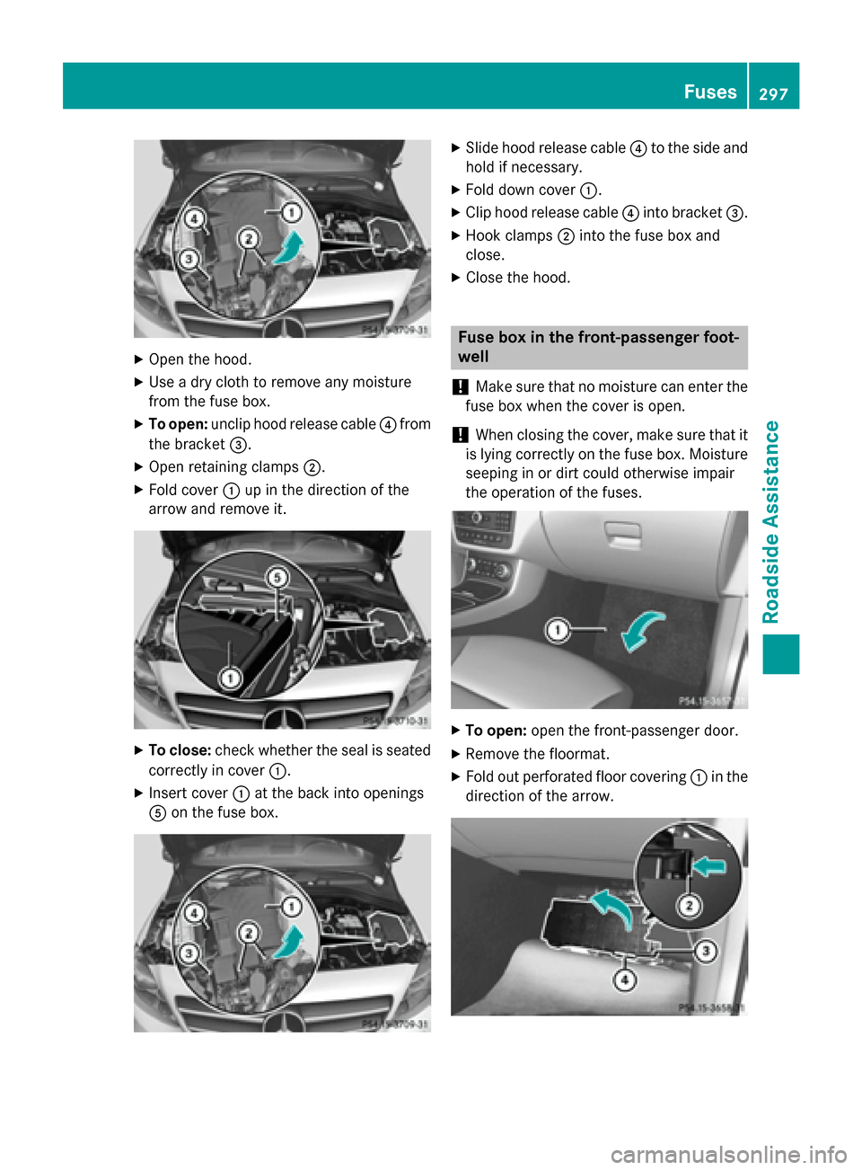
Open the hood.
X Use a dry cloth to remove any moisture
from the fuse box.
X To open: unclip hood release cable ?from
the bracket =.
X Open retaining clamps ;.
X Fold cover :up in the direction of the
arrow and remove it. X
To close: check whether the seal is seated
correctly in cover :.
X Insert cover :at the back into openings
A on the fuse box. X
Slide hood release cable ?to the side and
hold if necessary.
X Fold down cover :.
X Clip hood release cable ?into bracket =.
X Hook clamps ;into the fuse box and
close.
X Close the hood. Fuse box in the front-passenger foot-
well
! Make sure that no moisture can enter the
fuse box when the cover is open.
! When closing the cover, make sure that it
is lying correctly on the fuse box. Moisture seeping in or dirt could otherwise impair
the operation of the fuses. X
To open: open the front-passenger door.
X Remove the floormat.
X Fold out perforated floor covering :in the
direction of the arrow. Fuses
297Roadside Assistance Z