2015 MERCEDES-BENZ B-Class ELECTRIC display
[x] Cancel search: displayPage 283 of 338
X
Stop the vehicle on solid, non-slippery and
level ground, as far away as possible from
traffic.
X Switch on the hazard warning lamps.
X Secure the vehicle against rolling away
(Y page 153).
X If possible, bring the front wheels into the
straight-ahead position.
X Switch off the drive system.
X Vehicles without KEYLESS-GO: remove
the SmartKey from the ignition lock.
X Vehicles with KEYLESS-GO start-func-
tion or KEYLESS-GO: open the driver's
door.
The on-board electronics now have status
0. This is the same as the SmartKey having
been removed.
X Vehicles with KEYLESS-GO start-func-
tion or KEYLESS-GO: remove the Start/
Stop button from the ignition lock
(Y page 131).
X All occupants must get out of the vehicle.
Make sure that they are not endangered as
they do so.
X Make sure that no one is near the danger
area while a wheel is being changed. Any-
one who is not directly assisting in the
wheel change should, for example, stand
behind the barrier.
X Get out of the vehicle. Pay attention to traf-
fic conditions when doing so.
X Close the driver's door.
i Vehicles equipped with MOExtended tires
are not equipped with a TIREFIT kit at the
factory. It is therefore recommended that
you additionally equip your vehicle with a
TIREFIT kit if you mount tires that do not
feature run-flat properties, e.g. winter tires. A TIREFIT kit can be obtained from a quali-
fied specialist workshop. MOExtended tires (tires with run-flat
properties)
General notes With MOExtended tires (tires with run flat
characteristics), you can continue to drive
your vehicle even if there is a total loss of
pressure in one or more tires. The affected
tire must not show any clearly visible damage.
You can recognize MOExtended tires by the
MOExtended marking which appears on the
sidewall of the tire. You will find this marking next to the tire size designation, the load-
bearing capacity and the speed index
(Y page 315).
MOExtended tires may only be used in con-
junction with an active tire pressure monitor.
If a pressure loss warning message
appears in the multifunction display:
R observe the instructions in the display mes-
sages (Y page 221).
R check the tire for damage.
R if driving on, observe the following notes.
The driving distance possible in run-flat mode is approximately 50 miles (80 km) when the
vehicle is partially laden and approximately
18 miles (30 km) when the vehicle is fully
laden.
In addition to the vehicle load, the driving dis-
tance possible depends upon:
R vehicle speed
R road condition
R outside temperature
The driving distance possible in run-flat mode may be reduced by extreme driving condi-
tions/maneuvers, or it can be increased
through a moderate style of driving.
The driving distance possible in run-flat modeis counted from the moment the tire pressure
loss warning appears in the multifunction dis-
play.
You must not exceed a maximum speed of
50 mph (80 km/h). Flat tire
281Roadside Assistance
Page 290 of 338
The jump-starting connection point is in the
engine compartment (Y page 290).
X Open the hood.
X Connect the battery charger to the positive
terminal and ground point in the same
order as when connecting the donor bat-
tery in the jump-starting procedure
(Y page 290).
If the indicator/warning lamps do not light up at low temperatures, it is very likely that the
discharged battery has frozen. In this case
you may neither jump-start the vehicle nor
charge the battery. The service life of a
thawed-out battery may be shorter. The start-
ing characteristics can be impaired, particu-
larly at low temperatures. Have the thawed-
out battery checked at a qualified specialist
workshop.
Only charge the installed battery with a bat-
tery charger which has been tested and
approved by Mercedes-Benz. A battery
charger unit specially adapted for Mercedes-
Benz vehicles and tested and approved by
Mercedes-Benz is available as an accessory.
It permits the charging of the battery in its
installed position. Contact an authorized
Mercedes-Benz Center for further informa-
tion and availability. Read the battery charg-
er's operating instructions before charging
the battery. High-voltage battery – important
safety notes
G
DANGER
The vehicle's high voltage electrical system is under high voltage. If you modify components
in the vehicle's high-voltage electrical system or touch damaged components, you may be
electrocuted. The components in the vehi-
cle's high-voltage electrical system may be
damaged in an accident, although the damage
is not visible. There is a risk of fatal injury.
Following an accident, do not touch any high- voltage components and never modify the
vehicle's high-voltage electrical system. Have the vehicle towed away after an accident and
the vehicle's high-voltage electrical system
checked by a qualified specialist workshop. G
WARNING
In the event of a vehicle fire, the internal pres- sure of the high-voltage battery can exceed a
critical value. In this case flammable gas
escapes through a ventilation valve on the
underbody. The gas can ignite. There is a risk of injury.
Leave the danger zone immediately. Secure
the danger area at a suitable distance, whilst
observing legal requirements.
The vehicle's high voltage electrical system is under high voltage.
R Do not handle high-voltage components or
the orange cables of the vehicle's high-volt-age electrical system.
R Do not touch high-voltage components or
the orange cables of the high-voltage elec-
trical system when a vehicle has been
involved in a crash.
R Do not touch any damaged components or
the damaged orange cables of the vehicle's
high-voltage electrical system.
R Do not remove the covers of the high-volt-
age electrical system components that are
marked with a warning sticker.
Do not leave the vehicle parked for longer
than 14 days with a high-voltage battery con- dition of charge below 20%.
You can check the condition of charge in the
charge level display (Y page 184).
If you park the vehicle and leave it stationary for longer periods, connect it to a power sup-
ply.
If you leave the vehicle parked for longer than
four weeks, the battery may be damaged by
exhaustive discharging. 288
BatteriesRoadside Assistance
Page 295 of 338
!
When towing, pull away slowly and
smoothly. If the tractive power is too high,
the vehicles could be damaged.
! The vehicle can be towed a maximum of
30 miles (50km). The towing speed of
30 mph (50km/h) must not be exceeded.
If the vehicle has to be towed more than
30 miles (50km), the front axle must be
raised or the entire vehicle raised and
transported.
! Do not tow with sling-type equipment.
This could damage the vehicle.
! To tow vehicles with KEYLESS-GO, use
the SmartKey instead of the Start/Stop
button. The transmission may otherwise
shift to position Pwhen you open the driv-
er's or front-passenger door, which could
damage the transmission.
Observe the legal requirements for the rele-
vant countries when towing away.
Make sure that no charging cable is plugged
in. The parking lock cannot be released if a
charging cable is plugged in.
It is better to have the vehicle transported
than to have it towed away.
If the vehicle can no longer be driven because
of an accident or breakdown, you have the
following options:
R transporting the vehicle
As a rule, you should have the vehicle trans-
ported.
R towing the vehicle with a tow rope or tow
bar
Only tow the vehicle in exceptional cases.
Observe the following notes.
The vehicle may not be towed and must
always be transported if:
R the multifunction display is not working
R one of more of the following warning lamps
is lit up:
- Drive system
- 12 V battery R
one or both of the following display mes-
sages have appeared:
- Stop Switch Engine Off
Stop Switch Engine Off
- Service Required Do Not Shift Service Required Do Not Shift
Gears Visit Dealer Gears Visit Dealer
R the brake pedal begins to pulsate as the
towing procedure commences.
R you have to tow the vehicle over a longer
distance than 30 miles (50 km)
When towing a vehicle, the transmission must be in position N.
The battery must be connected and charged.
Otherwise, you:
R cannot turn the SmartKey to position 2in
the ignition lock
R cannot release the electric parking brake
R cannot shift the transmission to position N
i The function of the electric parking brake
and the parking lock is dependent on the
on-board voltage.
If the on-board voltage is low or there is a
system malfunction, it is possible that:
R the electric parking brake may not be
applied in certain circumstances, or
R the transmission may not be shifted to P
i Switch off non-essential consumers, e.g.
the radio.
i Disarm the automatic locking feature
(Y page 198). You could otherwise be
locked out when pushing or towing the
vehicle. Towing
293Roadside Assistance Z
Page 309 of 338
Checking tire pressures manually
To determine and set the correct tire pres-
sure, proceed as follows:
X Remove the valve cap of the tire that is to
be checked.
X Press the tire pressure gauge securely onto
the valve.
X Read the tire pressure and compare it to
the recommended value on the Tire and
Loading Information placard or the tire
pressure table (Y page 303).
X If the tire pressure is too low, increase the
tire pressure to the recommended value.
X If the tire pressure is too high, release air.
To do so, press down the metal pin in the
valve, using the tip of a pen for example.
Then check the tire pressure again using
the tire pressure checker.
X Screw the valve cap onto the valve.
X Repeat these steps for the other tires. Tire pressure monitor
General notes If a tire pressure monitor is installed, the vehi-
cle's wheels have sensors that monitor the
tire pressures in all four tires. The tire pres-
sure monitor warns you if the pressure drops
in one or more of the tires. The tire pressure
monitor only functions if the corresponding
sensors are installed in all wheels.
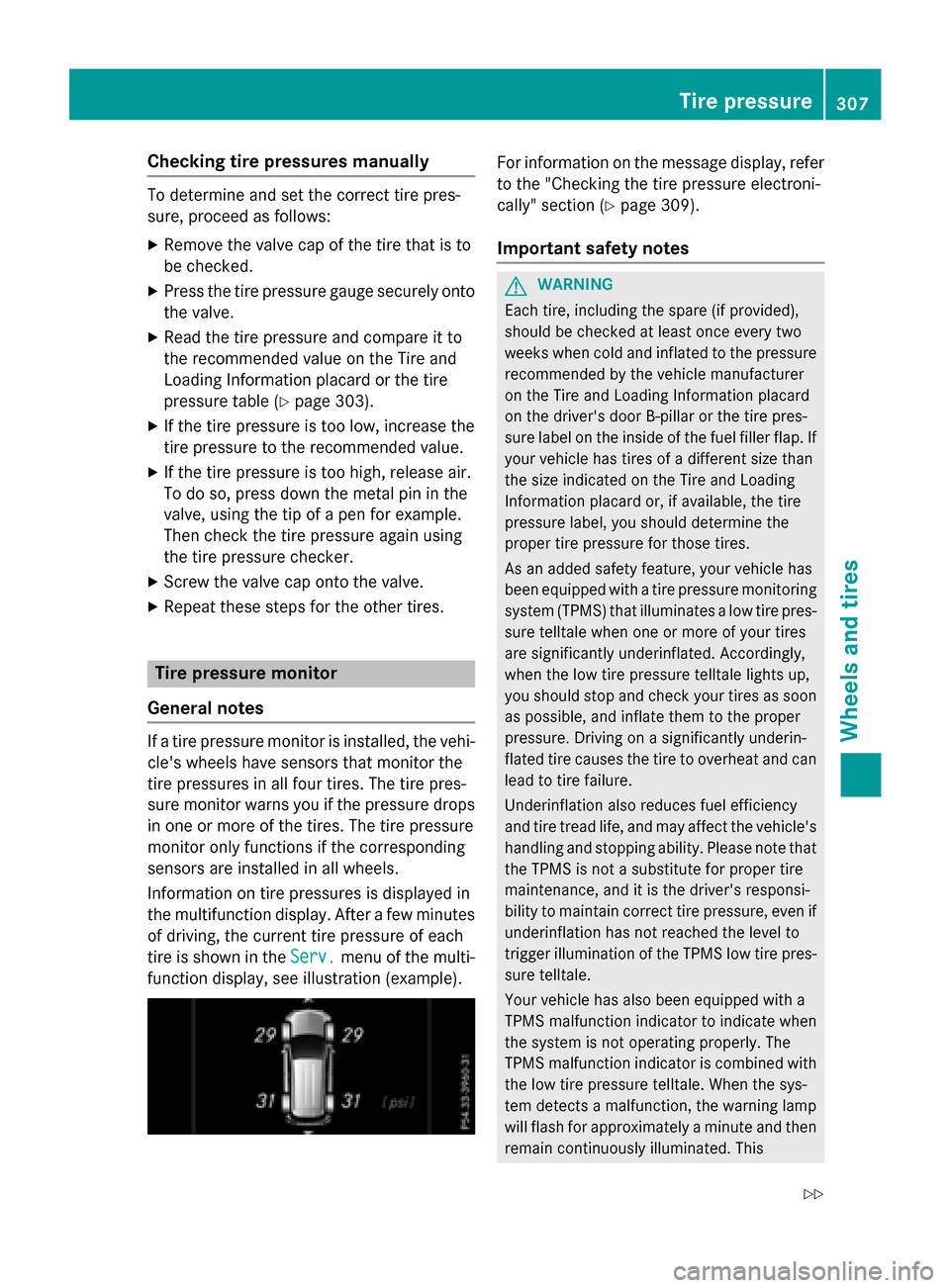
Information on tire pressures is displayed in
the multifunction display. After a few minutes of driving, the current tire pressure of each
tire is shown in the Serv. Serv.menu of the multi-
function display, see illustration (example). For information on the message display, refer
to the "Checking the tire pressure electroni-
cally" section (Y page 309).
Important safety notes G
WARNING
Each tire, including the spare (if provided),
should be checked at least once every two
weeks when cold and inflated to the pressure recommended by the vehicle manufacturer
on the Tire and Loading Information placard
on the driver's door B-pillar or the tire pres-
sure label on the inside of the fuel filler flap. If
your vehicle has tires of a different size than
the size indicated on the Tire and Loading
Information placard or, if available, the tire
pressure label, you should determine the
proper tire pressure for those tires.
As an added safety feature, your vehicle has
been equipped with a tire pressure monitoring system (TPMS) that illuminates a low tire pres-
sure telltale when one or more of your tires
are significantly underinflated. Accordingly,
when the low tire pressure telltale lights up,
you should stop and check your tires as soon
as possible, and inflate them to the proper
pressure. Driving on a significantly underin-
flated tire causes the tire to overheat and can
lead to tire failure.
Underinflation also reduces fuel efficiency
and tire tread life, and may affect the vehicle's handling and stopping ability. Please note that the TPMS is not a substitute for proper tire
maintenance, and it is the driver's responsi-
bility to maintain correct tire pressure, even if
underinflation has not reached the level to
trigger illumination of the TPMS low tire pres-
sure telltale.
Your vehicle has also been equipped with a
TPMS malfunction indicator to indicate when
the system is not operating properly. The
TPMS malfunction indicator is combined with
the low tire pressure telltale. When the sys-
tem detects a malfunction, the warning lamp
will flash for approximately a minute and then remain continuously illuminated. This Tire pressure
307Wheels and tires
Z
Page 310 of 338
sequence will be repeated every time the vehi-
cle is started as long as the malfunction
exists. When the malfunction indicator is illu-minated, the system may not be able to detect
or signal low tire pressure as intended.
TPMS malfunctions may occur for a variety of
reasons, including the installation of incom-
patible replacement or alternate tires or
wheels on the vehicle that prevent the TPMS
from functioning properly. Always check the
TPMS malfunction telltale after replacing one or more tires or wheels on your vehicle to
ensure that the replacement or alternate Tires and wheels allow the TPMS to continue to
function properly.
It is the driver's responsibility to set the tire
pressure to that recommended for cold tires
which is suitable for the operating situation
(Y page 303). Note that the correct tire pres-
sure for the current operating situation must
first be taught-in to the tire pressure monitor. If there is a substantial loss of pressure, the
warning threshold for the warning message is aligned to the reference values taught-in.
Restart the tire pressure monitor after adjust-
ing the pressure of the cold tires
(Y page 309). The current pressures are
saved as new reference values. As a result, a
warning message will appear if the tire pres-
sure drops significantly.
The tire pressure monitor does not warn you
of an incorrectly set tire pressure. Observe
the notes on the recommended tire pressure (Y page 303).
The tire pressure monitor is not able to warn
you of a sudden loss of pressure, e.g. if the
tire is penetrated by a foreign object. In the
event of a sudden loss of pressure, bring the
vehicle to a halt by braking carefully. Avoid
abrupt steering maneuvers. The tire pressure monitor has a yellow warn-
ing lamp in the instrument cluster for indicat-
ing a pressure loss or malfunction. Whether
the warning lamp flashes or lights up indi-
cates whether a tire pressure is too low or the tire pressure monitor is malfunctioning:
R if the warning lamp is lit continuously, the
tire pressure on one or more tires is signif-
icantly too low. The tire pressure monitor is
not malfunctioning.
R if the warning lamp flashes for around a
minute and then remains lit constantly, the
tire pressure monitor is malfunctioning.
In addition to the warning lamp, a message
appears in the multifunction display. Observe
the information on display messages
(Y page 221).
It may take up to ten minutes for a malfunc-
tion of the tire pressure monitor to be indica-
ted. A malfunction will be indicated by the tire
pressure warning lamp flashing for approx-
imately one minute and then remaining lit.
When the malfunction has been rectified, the
tire pressure warning lamp goes out after a
few minutes of driving.
The tire pressure values indicated by the on-
board computer may differ from those meas-
ured at a gas station with a pressure gauge.
The tire pressures shown by the on-board
computer refer to those measured at sea
level. At high altitudes, the tire pressure val-
ues indicated by a pressure gauge are higher
than those shown by the on-board computer. In this case, do not reduce the tire pressures.
The operation of the tire pressure monitor can be affected by interference from radio trans-
mitting equipment (e.g. radio headphones,
two-way radios) that may be being operated
in or near the vehicle. 308
Tire pressureWheels and tires
Page 311 of 338
Checking the tire pressure electroni-
cally
X
Make sure that the SmartKey is in position
2 in the ignition lock (Y page 131).
X Press =or; on the steering wheel
to select the Serv. Serv.menu.
X Press the 9or: button to select
Tire Pressure
Tire Pressure.
X Press the abutton.
The current tire pressure of each tire is
shown in the multifunction display.
If the vehicle was parked for longer than
20 minutes, the Tire pressure will be
Tire pressure will be
displayed after driving a few
displayed after driving a few
minutes minutes message is shown.
After a teach-in process, the tire pressure
monitor automatically detects new wheels or
new sensors. As long as a clear allocation of
the tire pressure value to the individual
wheels is not possible, the Tire Pressure
Tire Pressure
Monitor Active Monitor Active message is shown instead
of the tire pressure display. The tire pressures are already being monitored.
Tire pressure monitor warning mes-
sages If the tire pressure monitor detects a pressure
loss in one or more tires, a warning message
is shown in the multifunction display and the yellow tire pressure monitor warning lamp
comes on.
R If the Please Correct Tire Pressure
Please Correct Tire Pressure
message appears in the multifunction dis-
play, the tire pressure in at least one tire is
too low and must be corrected at the next
opportunity.
R If the Check Tire Pressure Check Tire Pressure message
appears in the multifunction display, the
tire pressure in one or more tires has drop-
ped significantly and the tires must be
checked.
R If the Tire Pressure Warning Tire Tire Pressure Warning Tire
Failure
Failure message appears in the multi-
function display, the tire pressure in one or more tires has dropped suddenly and the
tires must be checked.
Observe the instructions and safety notes in
the display messages in the "Tires" section
(Y page 221).
If the wheel positions on the vehicle are rota-
ted, the tire pressures may be displayed for
the wrong positions for a short time. This is
rectified after a few minutes of driving, and
the tire pressures are displayed for the cor-
rect positions.
Restarting the tire pressure monitor When you restart the tire pressure monitor, all
existing warning messages are deleted and
the warning lamps go out. The monitor uses
the currently set tire pressures as the refer-
ence values for monitoring. In most cases, the tire pressure monitor will automatically
detect the new reference values after you
have changed the tire pressure. However, you
can also define reference values manually as
described here. The tire pressure monitor
then monitors the new tire pressure values.
X Set the tire pressure to the value recom-
mended for the corresponding driving sit-
uation on the Tire and Loading Information
placard on the driver's side
B-pillar (Y page 303).
Additional tire pressure values for different operating conditions can also be found on
the tire pressure table on the inside of the
charge socket flap (Y page 148).
X Make sure that the tire pressure is correct
on all four wheels.
X Make sure that the SmartKey is in position
2 in the ignition lock (Y page 131).
X Press =or; on the steering wheel
to select the Serv.
Serv. menu.
X Press the 9or: button to select
Tire Pressure
Tire Pressure.
X Press the abutton.
The multifunction display shows the cur-
rent tire pressure for each tire or the Tire Tire Tire pressure
309Wheels and tires Z
Page 312 of 338
pressure will be displayed after
pressure will be displayed after
driving a few minutes
driving a few minutes message.
X Press the :button.
The multifunction display shows the Use
Use
current
current pressures
pressures as
asnew
new reference
reference
values
values message.
If you wish to confirm the restart:
X Press the abutton.
The Tire Press. Monitor Restarted
Tire Press. Monitor Restarted
message appears in the multifunction dis-
play.
After driving for a few minutes, the system checks whether the current tire pressures
are within the specified range. The new tire
pressures are then accepted as reference
values and monitored.
If you wish to cancel the restart:
X Press the %button.
The tire pressure values stored at the last
restart will continue to be monitored.
Radio type approval for the tire pres-
sure monitor Country Radio type approval number
USA FCC ID: MRXMW2433A
FCC ID: MRXGG4
FCC ID: MRXMC34MA4
Canada IC: 2546A-MW2433A
IC: 2546A-GG4
IC: 2546A-MC34MA4
Loading the vehicle
Instruction labels for tires and loads
G
WARNING
Overloaded tires can overheat, causing a
blowout. Overloaded tires can also impair the steering and driving characteristics and lead
to brake failure. There is a risk of accident.
Observe the load rating of the tires. The load
rating must be at least half of the GAWR of your vehicle. Never overload the tires by
exceeding the maximum load.
Two instruction labels on your vehicle show
the maximum possible load.
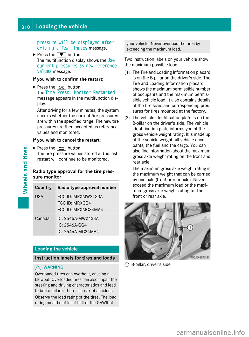
(1) The Tire and Loading Information placard is on the B-pillar on the driver's side. The
Tire and Loading Information placard
shows the maximum permissible number of occupants and the maximum permis-
sible vehicle load. It also contains details
of the tire sizes and corresponding pres-
sures for tires mounted at the factory.
(2) The vehicle identification plate is on the B-pillar on the driver's side. The vehicle
identification plate informs you of the
gross vehicle weight rating. It is made up
of the vehicle weight, all vehicle occu-
pants, the fuel and the cargo. You can
also find information about the maximum gross axle weight rating on the front and
rear axle.
The maximum gross axle weight rating is the maximum weight that can be carried
by one axle (front or rear axle). Never
exceed the maximum load or the maxi-
mum gross axle weight rating for the
front or rear axle. :
B-pillar, driver's side 310
Loading the vehicleWheels and tires