Page 17 of 25
 16
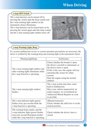
When Driving
Smart Brake Support (SBS)
Smart Brake Support (SBS) is a system which alerts the driver of a possible
collision using an indicator and warning sound in the instrument cluster while th")
16
When Driving
Smart Brake Support (SBS)
Smart Brake Support (SBS) is a system which alerts the driver of a possible
collision using an indicator and warning sound in the instrument cluster while the
vehicle is being driven at about 15 km/h or faster (10 mph or faster) and the
system's radar sensor (front) determines that your vehicle may hit a vehicle ahead.
Furthermore, if the radar sensor (front) determines that a collision is unavoidable,
the automatic brake control is performed to reduce damage in the event of a
collision.
For details, refer to Section 4, “Smart Brake Support (SBS)”.
Do not rely completely on the Smart Brake Support (SBS) system and always
drive carefully:
Smart Brake Support (SBS) is only designed to reduce damage in the event of a
collision. The ability to detect an obstruction is limited depending on the obstruction,
weather conditions, or traffic conditions. Therefore, if the accelerator pedal or brake
pedal is mistakenly operated it could result in an accident. Always verify the safety of
the surrounding area and depress the brake pedal or accelerator pedal while keeping
a safer distance from vehicles ahead or on-coming vehicles.
WARNING
�/�C�\�F�C���A���'�(�����'�'�������.�A�'�F�K�V�K�Q�P���A�3�W�K�E�M�)�W�K�F�G���K�P�F�D����������������������������������������������������
Page 18 of 25
 When Driving
17
Smart Brake Support (SBS)
NOTE
The Smart Brake Support (SBS) system may not operate under the following
conditions:
• The brake pedal, steering wheel, selector lever, or a direction")
When Driving
17
Smart Brake Support (SBS)
NOTE
The Smart Brake Support (SBS) system may not operate under the following
conditions:
• The brake pedal, steering wheel, selector lever, or a direction indicator is
operated.
Although the objects which activate the system are 4-wheeled vehicles, the
radar sensor (front) could detect the following objects, determine them to be an
obstruction, and operate the Smart Brake Support (SBS) system.
• Two-wheeled vehicles such as motorcycles and bicycles, pedestrians, trees
If there is the possibility of a collision with a
vehicle ahead, the beep sounds continuously
and a warning is indicated in the display.
Collision Warning
Other details are described in the related text.
Other details are described in the related text.
For details, refer to Section 4, “Smart Brake Support (SBS)”.
• If there is the possibility of hitting only a part of a vehicle ahead.
• The vehicle is driven at the same speed as the vehicle ahead.
• Objects on the road at the entrance to a curve (including guardrails and
snow banks).
• A vehicle appears in the opposite lane while cornering or rounding a curve.
• When crossing a narrow bridge, passing through a low gate or tunnel, a
narrow gate, or entering an underground parking area.
• Metal objects, bumps, or protruding objects on the road.
�/�C�\�F�C���A���'�(�����'�'�������.�A�'�F�K�V�K�Q�P���A�3�W�K�E�M�)�W�K�F�G���K�P�F�D����������������������������������������������������
Page 19 of 25
 18
When Driving
Electric components
Engine Components
Vehicle Systems:
Air-conditioning
Audio
Head-lights, etc
Accelerator OFF
Accelerator ONEnergy
regenerationChargeBattery
Battery Power
Power
E")
18
When Driving
Electric components
Engine Components
Vehicle Systems:
Air-conditioning
Audio
Head-lights, etc
Accelerator OFF
Accelerator ONEnergy
regenerationChargeBattery
Battery Power
Power
Electric components
Engine Components
Vehicle Systems:
Air-conditioning
Audio
Head-lights, etc
Engine
Variable
Voltage
alternator
Variable
Voltage
alternator Engine
Tyre TyreCapacitor
CapacitorDC-DC converter
DC-DC converter
Kinetic energy
Electrical power
i-ELOOP System
On conventional vehicles, the kinetic energy that is generated when the vehicle is
decelerated by applying the brakes or during engine braking ends up being discarded
as heat. By utilizing this discarded kinetic energy to generate electricity and use it to
power the vehicle's electrical devices and accessories such as the A/C and audio, fuel
consumption can be reduced. Mazda's system for generating electricity from this
kinetic energy is called the Regenerative Braking System (i-ELOOP).
i-ELOOP Warning Beep
The beep will sound if the vehicle is driven while the
i-ELOOP indicator light is flashing. Make sure that
the i-ELOOP indicator light has stopped flashing
before driving.
For details, refer to Section 4, “i-ELOOP” or Section 7,
“Warning/Indicator Lights and Warning Sounds”.
�/�C�\�F�C���A���'�(�����'�'�������.�A�'�F�K�V�K�Q�P���A�3�W�K�E�M�)�W�K�F�G���K�P�F�D����������������������������������������������������
Page 20 of 25
19
When Driving
For details, refer to Section 4, “i-ELOOP”.
The i-ELOOP power generating status is displayed in the audio display.
Indication on display
Control Status Display
Control status
Displays the level of electricity generated by
regenerative braking.
Displays the amount of the electricity stored
in the capacitor.
Displays the status of the electricity stored
in the capacitor and being supplied to the
electrical devices (whole vehicle in display
is illuminated simultaneously).
�/�C�\�F�C���A���'�(�����'�'�������.�A�'�F�K�V�K�Q�P���A�3�W�K�E�M�)�W�K�F�G���K�P�F�D����������������������������������������������������
Page 21 of 25
 20
When Driving
Diesel Particulate Filter
The diesel particulate filter collects and eliminates most of the particulate matter
(PM) in the exhaust gas of the diesel engine for improved exhaust gas pr")
20
When Driving
Diesel Particulate Filter
The diesel particulate filter collects and eliminates most of the particulate matter
(PM) in the exhaust gas of the diesel engine for improved exhaust gas processing
ability.
While the particulate matter (PM) collected in the diesel particulate filter is
eliminated automatically, fuel may be mixed with the engine oil increasing the
engine oil level. If the engine oil level exceeds the “X” mark on the dipstick,
replace the engine oil.
For details, refer to Section 4, “Tyre Pressure Monitoring System” or
“Diesel Particulate Filter”.
The Tyre Pressure Monitoring System (TPMS) monitors the air pressure of all
four tyres. If the air pressure of one or more tyres is too low, the system warns the
driver by indicating the tyre pressure monitoring system warning light in the
instrument cluster and operating a beep sound.
In the following cases, system initialization must be performed so that the system
operates normally.
• A tyre pressure is adjusted.
• Tyre rotation is performed.
• A tyre or wheel is replaced.
• The battery is replaced or completely drained.
• The tyre pressure monitoring system warning
light is illuminated.
Tyre Pressure Monitoring System
�/�C�\�F�C���A���'�(�����'�'�������.�A�'�F�K�V�K�Q�P���A�3�W�K�E�M�)�W�K�F�G���K�P�F�D����������������������������������������������������
Page 22 of 25
 Interior Features
21
Airflow display Temperature setting display (driver)
Mode selector
display A/C mode display
Temperature setting display (passenger)
Air intake selector
(recirculated air position")
Interior Features
21
Airflow display Temperature setting display (driver)
Mode selector
display A/C mode display
Temperature setting display (passenger)
Air intake selector
(recirculated air position)
Air intake selector
(outside air position) Driver temperature control dial
AUTO switch
Mode selector switch Fan control switchOFF switchWindscreen defroster switch
Rear window defogger switch
DUAL switch
A/C switch
Passenger temperature
control dial
Air-Conditioning System (Dual-Zone Automatic Type)
Operation of Automatic Air Conditioning
1. Press the AUTO switch. Selection of the airflow mode, air intake selector and
amount of airflow will be automatically controlled.
2. Use the temperature control dial to select a desired temperature.
3. To turn off the system, press the OFF switch.
Press the DUAL switch or turn the front passenger temperature control dial to
control the set temperature individually for the driver and front passenger.
For details, refer to Section 5, “Air-Conditioning System”.
�/�C�\�F�C���A���'�(�����'�'�������.�A�'�F�K�V�K�Q�P���A�3�W�K�E�M�)�W�K�F�G���K�P�F�D����������������������������������������������������
Page 23 of 25
 22
Maintenance and Care
Selector
X Mark Full Low
Inspecting Engine Oil Level
If the engine oil level exceeds the “X” mark on the dipstick, replace the engine oil.
For details, refer to Sec")
22
Maintenance and Care
Selector
X Mark Full Low
Inspecting Engine Oil Level
If the engine oil level exceeds the “X” mark on the dipstick, replace the engine oil.
For details, refer to Section 6, “Owner Maintenance”.
When inspecting the engine oil level, pull out the dipstick straight without
twisting.
In addition, when inserting the dipstick, always insert it without twisting so that
the “X” mark faces the front of the vehicle.
After replacing the engine oil, have a repair shop such as an Authorised Mazda
Repairer perform the initialization (engine oil data resetting) of the recorded value.
If the value recorded by the computer is not initialized, the wrench indicator light
may not turn off or it may turn on earlier than normal.
NOTE
The initialization (engine oil data resetting) of the recorded value can be
performed using the following procedure:
1. Switch the ignition OFF.
2. Switch the ignition ON with the selector pressed, and press and hold the
selector for about 5 seconds until the master warning light flashes.
3. After the master warning light flashes for several seconds, the initial-
ization is completed.
�/�C�\�F�C���A���'�(�����'�'�������.�A�'�F�K�V�K�Q�P���A�3�W�K�E�M�)�W�K�F�G���K�P�F�D����������������������������������������������������
Page 24 of 25
 23
Maintenance and Care
Windscreen washer
fluid reservoirBrake/Clutch fluid reservoir
Engine oil dipstick
BatteryFuse block
Cooling system cap
Engine coolant reservoir
Engine oil-filler cap SKYACTIV-")
23
Maintenance and Care
Windscreen washer
fluid reservoirBrake/Clutch fluid reservoir
Engine oil dipstick
BatteryFuse block
Cooling system cap
Engine coolant reservoir
Engine oil-filler cap SKYACTIV-G 1.5 and SKYACTIV-G 2.0
Windscreen washer
fluid reservoirBrake/Clutch fluid reservoir
Engine oil dipstickBattery
Fuse block
Cooling system capAutomatic transaxle fluid-level
dipstick (only for automatic transaxle)
Engine coolant reservoir Engine oil-filler cap MZR 1.6
Brake/Clutch fluid reservoir
Engine oil dipstick
Battery
Fuse block
Cooling system cap
Engine coolant reservoir
Engine oil-filler cap SKYACTIV-D 2.2Windscreen washer
fluid reservoir
Owner Maintenance Precautions
Routine Service
We highly recommend that these items be inspected daily, or at least every week.
• Engine Oil Level
• Engine Coolant Level
• Brake and Clutch Fluid Level
• Washer Fluid Level
• Battery Maintenance
• Tyre Inflation Pressure
For details, refer to Section 6, “Owner Maintenance”.
�/�C�\�F�C���A���'�(�����'�'�������.�A�'�F�K�V�K�Q�P���A�3�W�K�E�M�)�W�K�F�G���K�P�F�D����������������������������������������������������


 19
When Driving
For details, refer to Section 4, “i-ELOOP”.
The i-ELOOP power generating status is displayed in the audio display.
Indication on display
Control Status Display
Control status
Displ")