Page 754 of 785
779
Maintenance
DescriptionFuse ratingProtected Component
FUSE
4WD20AAWD ECM
AMS10ABattery Sensor
AMS (WIPER)10ABCM, PCM
WIPER FRT25AWiper LO Relay, Front Wiper Motor
B/UP LAMP10AM/T - Back-Up Lamp Switch, A/T - Rear Combination Lamp (IN) LH/RH, Electro Chromic
Mirror, Audio, A/V & Navigation Head Unit
ABS37.5AESC Module
SENSOR57.5APCM
TCU15AA/T : Transaxle Range Switch, M/T : Fuse - B/UP LAMP (M/T)
F/PUMP15AFuel Pump Relay
ECU 115APCM
ECU 210A-
SENSOR 310AFuel Pump Relay, Camshaft Position Sensor #1/#2
IGN COIL20ACondenser, Ignition Coil #1/#2/#3/#4
SENSOR 210APurge Control Solenoid Valve, Variable Intake Solenoid Valve(G4KJ), RCV Control Solenoid
Valve(G4KH),Crankshaft Position Sensor, Oil Control Valve #1/#2, Canister Close Valve
SENSOR 115AOxygen Sensor (Up), Oxygen Sensor(Down), E/R Fuse & Relay Box (Cooling Fan Relay)
SENSOR 420APCM
B/A HORN10ABurglar Alarm Horn Relay
Page 757 of 785

Maintenance
82 7
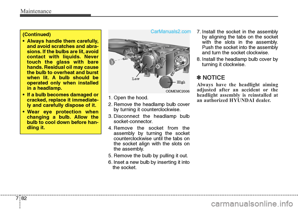
1. Open the hood.
2. Remove the headlamp bulb cover
by turning it counterclockwise.
3. Disconnect the headlamp bulb
socket-connector.
4. Remove the socket from the
assembly by turning the socket
counterclockwise until the tabs on
the socket align with the slots on
the assembly.
5. Remove the bulb by pulling it out.
6. Inset a new bulb by inserting it into
the socket.7. Install the socket in the assembly
by aligning the tabs on the socket
with the slots in the assembly.
Push the socket into the assembly
and turn the socket clockwise.
8. Install the headlamp bulb cover by
turning it clockwise.
✽NOTICE
Always have the headlight aiming
adjusted after an accident or the
headlight assembly is reinstalled at
an authorized HYUNDAI dealer.
(Continued)
• Always handle them carefully,
and avoid scratches and abra-
sions. If the bulbs are lit, avoid
contact with liquids. Never
touch the glass with bare
hands. Residual oil may cause
the bulb to overheat and burst
when lit. A bulb should be
operated only when installed
in a headlamp.
• If a bulb becomes damaged or
cracked, replace it immediate-
ly and carefully dispose of it.
• Wear eye protection when
changing a bulb. Allow the
bulb to cool down before han-
dling it.
ODMEMC2006
L L
o o
w wH H
i i
g g
h h
Page 758 of 785
783
Maintenance
Turn signal lamp/Position lamp
1. Remove the socket from the
assembly by turning the socket
counterclockwise until the tabs on
the socket align with the slots on
the assembly.
2. Remove the bulb from the socket
by pressing it in and rotating it
counterclockwise until the tabs on
the bulb align with the slots in the
socket. Pull the bulb out of the
socket
3. Insert a new bulb by inserting it
into the socket and rotating it until
it locks into place.4. Install the socket in the assembly
by aligning the tabs on the socket
with the slots in the assembly.
Push the socket into the assembly
and turn the socket clockwise.
Front fog lamp bulbs
(if equipped)
If the lamp bulb does not operate,
have the vehicle checked by an
authorized HYUNDAI dealer.
ODMEMC2006
T T
u u
r r
n n
s s
i i
g g
n n
a a
l l
P P
o o
s s
i i
t t
i i
o o
n n
l l
a a
m m
p p
ODMEMC2008
Page 760 of 785
785
Maintenance
Rear combination lamp bulb
replacement
(1) Rear stop and tail lamp
(2) Rear tail lamp
(3) Rear turn signal lamp
(4) Back-up lamp
(5) Rear side marker
Outside lamp
1. Open the tailgate.
2. Remove the service cover using a
flat-blade screwdriver.
3. Loosen the lamp assembly retain-
ing please verify.
4. Remove the rear combination
lamp assembly from the body of
the vehicle.
5. Remove the socket from the
assembly by turning the socket
counterclockwise until the tabs on
the socket align with the slots on
the assembly.
ODM072033
ODMEMC2007
■Type A
■Type BODM072034
ODM072035
ODMEMC2010 ■Type A
■Type B
Page 761 of 785
Maintenance
86 7
6. Remove the bulb from the socket by
pressing it in and rotating it counter-
clockwise until the tabs on the bulb
align with the slots in the socket.
Pull the bulb out of the socket. (Side
marker : Remove the bulb from the
socket by pulling it out)
7. Insert a new bulb by inserting it
into the socket and rotating it until
it locks into place.
8. Install the socket in the assembly
by aligning the tabs on the socket
with the slots in the assembly.
Push the socket into the assembly
and turn the socket clockwise.
9. Reinstall the lamp assembly to the
body of the vehicle.Inside lamp
1. Open the tailgate.
2. Remove the service cover using a
flat-blade screwdriver.
3. Remove the socket from the
assembly by turning the socket
counterclockwise until the tabs on
the socket align with the slots on
the assembly.
OANNMC2036
ODM072037
ODMEMC2011
■Type A
■Type B
B B
a a
c c
k k
- -
u u
p p
l l
a a
m m
p p
S S
t t
o o
p p
/ /
t t
a a
i i
l l
l l
a a
m m
p p
Page 762 of 785
787
Maintenance
4. Remove the bulb from the socket
by pressing it in and rotating it
counterclockwise until the tabs on
the bulb align with the slots in the
socket. Pull the bulb out of the
socket. (Back-up lamp : Remove
the bulb from the socket by pulling
it out)
5. Insert a new bulb by inserting it
into the socket and rotating it until
it locks into place.
6. Install the socket in the assembly
by aligning the tabs on the socket
with the slots in the assembly.
Push the socket into the assembly
and turn the socket clockwise.
7. Install the service cover by putting
it into the service hole.High mounted stop lamp
replacement (if equipped)
1.Open the tailgate.
2.Gently remove the center cover of
the rear tailgate trim.
3.Disconnect the electrical connector.4.Loosen the retaining nuts and
remove the spoiler.
ODMEMC2018
ODMEMC2019
ODMEMC2022
Page 764 of 785
789
Maintenance
Interior lamp bulb replacement
1. Using a flat-blade screwdriver,
gently pry the lens from the interior
lamp housing.
2. Remove the bulb by pulling it
straight out.
3. Install a new bulb in the socket.
4. Align the lens tabs with the interior
lamp housing notches and snap
the lens into place.
■Map lamp
OXM079044/ODM072041/ODM072043
■Glove box lamp (if equipped)
■Luggage room lamp (if equipped)
■Sunvisor lamp■Room lamp
ODM072040/ODM072042/ODM072052■Type A
■Type B
WARNING
Prior to working on the Interior
Lamps, ensure that the “OFF”
button is depressed to avoid
burning your fingers or receiv-
ing an electric shock.
CAUTION
Use care not to dirty or damage
lens, lens tab, and plastic hous-
ings.
Page 772 of 785

797
Maintenance
EMISSION CONTROL SYSTEM
The emission control system of your
vehicle is covered by a written limited
warranty. Please see the warranty
information contained in the Service
Passport in your vehicle.
Your vehicle is equipped with an
emission control system to meet all
emission regulations.
There are three emission control
systems which are as follows.
(1) Crankcase emission control sys-
tem
(2) Evaporative emission control sys-
tem
(3) Exhaust emission control system
In order to assure the proper function
of the emission control systems, it is
recommended that you have your
car inspected and maintained by an
authorized HYUNDAI dealer in
accordance with the maintenance
schedule in this manual.Caution for the Inspection and
Maintenance Test (With Electronic
Stability Control (ESC) system)
• To prevent the vehicle from mis-
firing during dynamometer test-
ing, turn the Electronic Stability
Control (ESC) system off by
pressing the ESC switch.
• After dynamometer testing is
completed, turn the ESC system
back on by pressing the ESC
switch again.
1. Crankcase emission control
system
The positive crankcase ventilation
system is employed to prevent air
pollution caused by blow-by gases
being emitted from the crankcase.
This system supplies fresh filtered air
to the crankcase through the air
intake hose. Inside the crankcase,
the fresh air mixes with blow-by
gases, which then pass through the
PCV valve into the induction system.
2. Evaporative emission con-
trol (including ORVR:
Onboard Refueling Vapor
Recovery) system
The Evaporative Emission Control
System is designed to prevent fuel
vapors from escaping into the atmos-
phere.
(The ORVR system is designed to
allow the vapors from the fuel tank to
be loaded into a canister while refu-
eling at the gas station, preventing
the escape of fuel vapors into the
atmosphere.)
Canister
Fuel vapors generated inside the fuel
tank are absorbed and stored in the
onboard canister. When the engine is
running, the fuel vapors absorbed in
the canister are drawn into the surge
tank through the purge control sole-
noid valve.
Page:
< prev 1-8 9-16 17-24