Page 225 of 449

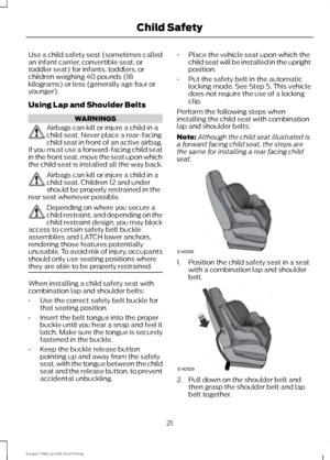
1. Press the locking buttons together.
2. Remove the wiper blade.
3. Install in the reverse order.
Note:
Make sure that the wiper blade locks
into place. Lower the wiper arm and blade
back to the windshield. The wiper arms will
automatically return to their normal position
when you switch the ignition on.
Rear Wiper Blade
Lift the wiper arms away from the rear
window. 1. Remove the wiper blade.
2. Install in the reverse order. Note:
Make sure that the wiper blade locks
into place.
ADJUSTING THE HEADLAMPS
Vertical Aim Adjustment
The headlamps on your vehicle are
properly aimed at the assembly plant. If
your vehicle has been in an accident, the
alignment of your headlamps should be
checked by your authorized dealer. 8 feet (2.4 meters)
A
Center height of lamp to ground
B
25 feet (7.6 meters)
C
Horizontal reference line
D
Vehicles With Halogen Headlamps
1. Park the vehicle directly in front of a wall or screen on a level surface,
approximately 25 feet (7.6 meters)
away.
2. Measure the height of the headlamp bulb center from the ground and mark
an 8 foot (2.4 meter) horizontal
reference line on the vertical wall or
screen at this height.
Note: To see a clearer light pattern for
adjusting, you may want to block the light
from one headlamp while adjusting the
other.
222
Escape (TM2), enUSA, First Printing MaintenanceE129990
1
1 2 E183236 E142592
Page 226 of 449

3. Turn on the low beam headlamps to
illuminate the wall or screen and open
the hood. 4. On the wall or screen you will observe
a flat zone of high intensity light
located at the top of the right hand
portion of the beam pattern. If the top
edge of the high intensity light zone is
not at the horizontal reference line, the
headlamp will need to be adjusted. 5. Locate the vertical adjuster on each
headlamp. Using a Phillips #2
screwdriver, turn the adjuster either
clockwise or counterclockwise in order
to aim the headlamp. The horizontal
edge of the brighter light should touch
the horizontal reference line.
6. Close the hood and turn off the lamps. Vehicles With High Intensity Discharge
Headlamps
1. Park the vehicle directly in front of a
wall or screen on a level surface,
approximately 25 feet (7.6 meters)
away.
2. Measure the height of the headlamp bulb center from the ground and mark
an 8 foot (2.4 meter) horizontal
reference line on the vertical wall or
screen at this height.
Note: To see a clearer light pattern for
adjusting, you may want to block the light
from one headlamp while adjusting the
other.
3. Turn on the low beam headlamps to illuminate the wall or screen and open
the hood. 4.
There is a distinct cut-off (change from
light to dark) in the left portion of the
beam pattern. The top edge of this
cut-off should be positioned two
inches (5 centimeters) below the
horizontal reference line.
223
Escape (TM2), enUSA, First Printing MaintenanceE142465 E142467 E142466
Page 227 of 449

5. Locate the vertical adjuster on each
headlamp. Using a Phillips #2
screwdriver, turn the adjuster either
clockwise or counterclockwise in order
to aim the headlamp.
6. Close the hood and turn off the lamps.
Horizontal Aim Adjustment
Horizontal aim is not required for this
vehicle and is non-adjustable.
REMOVING A HEADLAMP 1. Make sure the headlamp control is in
the off position and open the hood.
2. Remove the two screws from the headlamp assembly. 3. Carefully pull the headlamp assembly
as far as possible towards the front of
the vehicle to disengage it from the
lower fixing point.
4. Carefully lift the outer side of the headlamp and remove it.
5. Disconnect the electrical connector.
CHANGING A BULB
Lamp Assembly Condensation
Exterior lamps are vented to
accommodate normal changes in pressure.
Condensation can be a natural by-product
of this design. When moist air enters the
lamp assembly through the vents, there is
a possibility that condensation can occur
when the temperature is cold. When
normal condensation occurs, a thin film of
mist can form on the interior of the lens.
The thin mist eventually clears and exits
through the vents during normal operation.
Clearing time may take as long as 48 hours
under dry weather conditions.
Examples of acceptable condensation are:
• Presence of thin mist (no streaks, drip
marks or droplets).
• Fine mist covers less than 50% of the
lens.
Examples of unacceptable moisture
(usually caused by a lamp water leak) are:
• Water puddle inside the lamp.
• Large water droplets, drip marks or
streaks present on the interior of the
lens.
Take your vehicle to a dealer for service if
any of the above conditions of
unacceptable moisture are present.
224
Escape (TM2), enUSA, First Printing MaintenanceE142467 2
2
E142468
Page 228 of 449

Replacing Headlamp Bulbs
WARNING
Handle a halogen headlamp bulb
carefully and keep out of children
’s
reach. Grasp the bulb by only its
plastic base and do not touch the glass.
The oil from your hand could cause the
bulb to break the next time the headlamps
are operated. Note:
If the bulb is accidentally touched, it
should be cleaned with rubbing alcohol
before being used.
Headlamp: Side marker
A
Low beam headlamp
B
High beam headlamp
C
High beam headlamp: 1. Remove the headlamp.
2. Remove service cap.
3. Disconnect the electrical connector.
4. Remove bulb from the headlamp
assembly by turning it
counterclockwise, then pull it straight
out.
Low beam headlamp: 1. Remove the headlamp.
2. Remove service cap.
3. Disconnect the electrical connector.
4. Remove bulb from the headlamp
assembly by turning it
counterclockwise, then pull it straight
out.
Install the new bulbs in reverse order from
the steps above. Be sure that the spring
clip is not damaged or detached from the
headlamp assembly during the
replacement procedure.
Replacing HID Headlamp Bulbs (If
Equipped)
The low beam headlamps on your vehicle
use a high intensity discharge source.
These lamps operate at a high voltage.
When the bulb is burned out, the bulb and
starter capsule assembly must be replaced
by your authorized dealer.
225
Escape (TM2), enUSA, First Printing MaintenanceABC
E142469 24
E142470 24
E142471
Page 229 of 449
Replacing Side Marker Bulbs
1. Remove the bulb socket from the
headlamp assembly by turning it
counterclockwise.
2. Remove the bulb by gently pull the bulb straight out of the socket.
Install the new bulb in reverse order.
Replacing Fog, Park and Turn
Signal Bulbs Fog Lamp
A
Park Lamp
B
Turn Signal lamp
C 1. Remove the screws from the splash
shield at the wheel well to gain access
to the lamp assembly. 2.
Remove the bulb holder from the lamp
assembly by turning it
counterclockwise.
3. Disconnect the electrical connector.
4. Remove the bulb from the bulb holder
by pulling it straight out.
Install the new bulbs in reverse order from
the steps above.
226
Escape (TM2), enUSA, First Printing MaintenanceE142472 ABC
E142797 E142798 E142799
Page 230 of 449

Replacing Tail, Brake and Turn
Signal Bulbs
1. Make sure the headlamp control is in
the off position and open the liftgate.
2. Remove the two bolt covers using a standard flat tip screwdriver.
3. Remove the two bolts from the lamp assembly.
4. Gently pull the lamp assembly away from the vehicle. 5. Disconnect the electrical connector. 6.
Remove the turn signal bulb or the tail
and brake bulb by turning the bulb
socket counterclockwise. Gently pull
the bulb straight out of the socket.
Install the new bulb in reverse order.
Replacing Reverse Lamp Assembly
For bulb replacement, see your authorized
dealer.
Replacing License Plate Lamp Bulb 1. Carefully release the spring clip.
2. Remove the lamp.
3. Remove the bulb.
Reverse steps to reinstall bulb.
Replacing High-Mount Brake Lamp
Bulb
Your vehicle is equipped with an LED
center high-mount stop lamp located in
the spoiler. It is designed to last the life of
the vehicle. If replacement is required, see
your authorized dealer.
227
Escape (TM2), enUSA, First Printing Maintenance2
3
E142473 E142475 3
2
1
E72789
Page 231 of 449

BULB SPECIFICATION CHART
Replacement bulbs are specified in the
chart below. Headlamp bulbs must be
marked with an authorized
“D.O.T.” for North America to ensure lamp
performance, light brightness and pattern
and safe visibility. The correct bulbs will
not damage the lamp assembly or void the
lamp assembly warranty and will provide
quality bulb burn time. Trade number
Function
9005LL
Headlamps high beam (Halogen)
H1
* Headlamps high beam (HID)
H11LL
Headlamp low beam (Halogen)
D3S
* Headlamp low beam (HID)
168
Sidemarker - front
WY5W
Park lamp - front (HI Series)
194
Park lamp - front (Low Series)
WY21W
Turn lamp - front (HI Series)
W21W
Turn lamp - front (Low Series)
H10 (9145)
Fog lamps
3157K
Tail/brake lamp
T20
Turn lamp - rear
921
Backup lamp
W5W
License plate lamp
LED
* High-mount brake lamp
LED
* Interior lamps
* To replace these lamps - see your authorized dealer.
To replace all instrument panel lights - see your authorized dealer
228
Escape (TM2), enUSA, First Printing Maintenance
Page 232 of 449

CHANGING THE ENGINE AIR
FILTER
WARNING
To reduce the risk of vehicle damage
and personal burn injuries do not
start your engine with the air cleaner
removed and do not remove it while the
engine is running. When changing the air filter element, use
only the air filter element listed. See
Capacities and Specifications (page
264).
For EcoBoost equipped vehicles: When
servicing the air cleaner, it is important that
no foreign material enter the air induction
system. The engine and turbocharger are
susceptible to damage from even small
particles.
Change the air filter element at the proper
interval. See
Scheduled Maintenance
(page 420).
Note: Failure to use the correct air filter
element may result in severe engine
damage. The customer warranty may be
void for any damage to the engine if the
correct air filter element is not used.
1.6L and 2.0L EcoBoost Engines 1. Loosen the four fasteners and remove
the air cleaner assembly lid. 2.
Remove the air filter element from the
air filter housing.
3. Wipe any dirt or debris from the air cleaner assembly to make sure no dirt
gets in the engine and to make sure you
have a good seal. 4. Install the new air filter element. Slide
the open end of the air filter element
in first, below the tab. Then push the
closed end of the air filter into the
bottom of the tray. The closed end
should fit inside the groove in the tray.
The tab of the closed end of the air
filter should be oriented down and fit
between the forks on the tray as shown
at the arrow above.
Note: Make sure you align the tab in the air
filter element with the fork in the air cleaner
assembly tray.
5. Install the air cleaner assembly lid and
tighten the four fasteners.
229
Escape (TM2), enUSA, First Printing MaintenanceE171370 E170433