Page 137 of 240
, then reposition the jack
and the used tools;
❒reposition the boot mat then
reposition the reconfigurable loa")
❒place the punctured tyre in the boot
upside down (with the outer part facing
upwards), then reposition the jack
and the used tools;
❒reposition the boot mat then
reposition the reconfigurable load
platform in a flat position (see "Boot" in
the "Knowing your vehicle" chapter).
Restore the standard wheel as soon as
possible, because, once placed in the
associated compartment, the boot load
platform is rendered uneven as the
standard wheel is larger than the
space-saver wheel.
WARNING
132)If left in the passenger compartment,
the punctured wheel and jack constitute
a serious risk to the safety of occupants in
the event of accidents or sharp braking.
Therefore, always place both the jack and
punctured wheel in the dedicated housing
in the boot.
133)It is extremely dangerous to attempt
to change a wheel on the side of the
vehicle next to the driving lane: make sure
that the vehicle is at a sufficient distance
from the road, to avoid being run over.
134)Alert other drivers that the vehicle is
stationary in compliance with local
regulations: hazard warning lights, warning
triangle, etc. Any passengers on board
should leave the vehicle, especially if it is
heavily laden. Passengers should stay
away from on-coming traffic while the
wheel is being changed. For safety
reasons, always block the wheels with the
chocks provided.135)The vehicle's driving characteristics
will be modified with the space-saver wheel
fitted. Avoid violent acceleration and
braking, abrupt steering and fast cornering.
The overall duration of the space-saver
wheel is about 3000 km, after which the
relevant tyre must be replaced with another
one of the same type. Never install a
standard tyre on a rim that is designed for
use with a space-saver wheel. Have the
wheel repaired and refitted as soon as
possible. Using two or more space-saver
wheels at the same time is forbidden.
Do not grease the threads of the stud bolts
before fitting them: they might slip out
when driving!
136)The space-saver wheel is specific to
your vehicle: do not use it on other models,
or use the space-saver wheel of other
models on your vehicle. The space-saver
wheel must only be used in the event of an
emergency. It must only be used for the
distance necessary to reach a service point
and the vehicle speed must not exceed
80 km/h. The space-saver wheel has
an orange label that summarises the main
cautions for use and limitations. Never
remove or cover the sticker.
126
F1B0225C
135
15-12-2014 8:23 Pagina 135
Page 138 of 240
The jack is a tool developed and
designed only for changing a wheel, if a
tyre gets punctured or damaged, on the
vehicle with which it is supplied or on other
vehicles of the same model. It must n")
137)The jack is a tool developed and
designed only for changing a wheel, if a
tyre gets punctured or damaged, on the
vehicle with which it is supplied or on other
vehicles of the same model. It must not
be used, for example, to jack other vehicle
models or objects. Never use the jack to
carry out maintenance or repairs under the
vehicle. Never position yourself under a
jacked vehicle. Should it be necessary to
work under the vehicle, contact a Fiat
Dealership. Incorrectly positioning the jack
may cause the vehicle to fall: use it only
in the positions indicated. Do not use the
jack for loads higher than the one shown
on its label.
138)The space-saver wheel cannot be
fitted with snow chains. If a front (drive) tyre
is punctured and chains are needed, use
a standard wheel from the rear axle and
install the space-saver wheel on the rear
axle. In this way, with two normal drive
wheels at the front axle, it is possible to use
snow chains (this instruction is also valid
for 4x4 versions).
139)Never tamper with the inflation valve.
Never introduce tools of any kind between
the rim and the tyre. Check tyre and
space-saver wheel pressures regularly,
complying with the values given in the
"Technical specifications" chapter.
FIX&GO AUTOMATIC
KIT(where provided)DESCRIPTION
140) 141) 142) 143) 144) 145) 146) 147)54)3)
The Fix&Go automatic kit fig. 127 is
located in the boot, inside a dedicated
container. The container is also
equipped with a screwdriver, the tow
hook and the refuelling adaptor.
To access the Fix&Go automatic kit,
open the tailgate, position the
reconfigurable load platform in an
inclined position and lift the carpet. For
more detailed information, refer to
previous paragraph "Changing a
wheel".
The Fix&Go automatic kit also includes:
❒bottle A containing sealant and
fitted with: filling tube B and adhesive
label C with the wording “Max.
80 km/h” to be placed in a clearly
visible position (e.g. on the dashboard)
after repairing the tyre;
❒a compressor D complete with
pressure gauge and connectors;❒an instruction leaflet, to refer to for
prompt and correct use and that must
be then given to the personnel dealing
with the tyre treated with sealant;
❒a pair of gloves located in the side
compartment of the compressor;
❒some adaptors, for inflating different
elements.
IMPORTANT The sealing fluid is
effective with external temperatures of
between –20°C and +50°C. The sealing
fluid has an expiry date.
INFLATION PROCEDUREProceed as follows:
❒engage the electric parking brake,
unscrew the tyre valve cap, take out
filler hose A fig. 128 and tighten ring nut
B on the tyre valve;127
F1B0227C
136
IN AN EMERGENCY
15-12-2014 8:23 Pagina 136
Page 139 of 240
, start
the engine, insert the plug into the
power socket located on the central
tunnel and switch on the compressor
by bringing the")
❒make sure that the switch for the
compressor is in position0(off), start
the engine, insert the plug into the
power socket located on the central
tunnel and switch on the compressor
by bringing the switch to positionI(on);
❒inflate the tyre to the pressure
indicated in the “Wheels” paragraph
(see “Technical data” chapter). In order
to obtain a more precise reading, check
the pressure value on pressure gauge
B with the compressor off;
❒if after five minutes pressure is not at
least 1.8 bar, disengage the
compressor from the valve and power
socket, then move the vehicle forwards
by approx. ten metres in order to
distribute the sealing fluid inside the tyre
evenly, then repeat the inflation
operation;❒if after this operation you still cannot
reach at least 1.8 bar after 5 minutes
from switching on the compressor,
do not resume driving but contact a
Fiat Dealership;
❒after having driven for about 10
minutes, stop and re-check the tyre
pressure; remember to engage the
electric parking brake;
❒if a pressure value of at least 1.8 bar
is detected, restore the correct
pressure (with engine running and
electric parking brake engaged),
resume driving immediately and drive
with great care to a Fiat Dealership.
WARNING
140)Punctures on the sides of the tyre
may not be repaired. Do not use the
Fix&Go automatic kit if the tyre is damaged
due to travelling when flat.
141)Wear the protective gloves provided
with the Fix&Go automatic kit.
142)Apply the adhesive label where it can
be easily seen by the driver as a reminder
that the tyre has been treated with the
Fix&Go automatic kit. Drive carefully,
particularly on bends. Do not exceed 80
km/h. Do not accelerate or brake suddenly.
143)If the pressure has fallen below 1.8
bar, do not drive any further: the Fix&Go
automatic kit cannot guarantee proper hold
because the tyre is too damaged. Contact
a Fiat Dealership.144)You must always indicate that the tyre
was repaired using the Fix&Go automatic
kit. Give the leaflet to the technicians who
will be handling the tyre that was treated
using the Fix&Go automatic kit.
145)Repair is not possible if the wheel rim
is damaged (tread is deformed, causing
air to escape). Do not remove foreign
bodies (screws or nails) from the tyre.
146)Do not operate the compressor for
longer than 20 minutes consecutively. Risk
of overheating. The Fix&Go automatic kit
is not suitable for definitive repairs, so
the repaired tyres may only be used
temporarily.
147)The bottle contains ethylene glycol
and latex: it may cause an allergic reaction.
It is harmful if swallowed. It is irritant for
the eyes. It may cause sensitisation if
inhaled or on contact. Avoid contact with
eyes, skin and clothes. In the case of
contact, wash immediately with plenty of
water. In the event that it is swallowed, do
not induce vomiting. Rinse out your mouth,
drink large quantities of water and seek
immediate medical attention. Keep out of
the reach of children. The product must
not be used by asthmatics. Do not inhale
the vapours during insertion and suction.
Call a doctor immediately if allergic
reactions are noted. Store the bottle in its
proper compartment, away from sources
of heat. The sealant has an expiry date.
Replace the cylinder containing the sealant
after the expiry date.
128
F1B0229C
137
15-12-2014 8:23 Pagina 137
Page 140 of 240
In the event of a puncture caused by
foreign bodies, the kit may be used to
repair tyres showing damage on the tread
or shoulder up to max. 4 mm diameter.
WARNING
3)Dispose of the bottle an")
WARNING
54)In the event of a puncture caused by
foreign bodies, the kit may be used to
repair tyres showing damage on the tread
or shoulder up to max. 4 mm diameter.
WARNING
3)Dispose of the bottle and the sealant
properly. Dispose of the components
in compliance with national and local
regulations.
EMERGENCY
STARTING
55)
If the battery is flat, a jump starting can
be performed using the battery and
the cables of another vehicle, or using
an auxiliary battery. In all cases, the
battery used must have a capacity
equal to or a little higher than the flat
one.IMPORTANTDo not use an auxiliary battery or any
other source of external supply with
a voltage above 12 V: the battery, the
starter, the alternator and the electrical
system of the vehicle could be
damaged.
Do not attempt jump starting if the
battery is frozen. The battery could
break and explode!JUMP STARTINGThe vehicle battery is located in the
engine compartment, behind the left
light cluster.
148) 149) 150) 151)
IMPORTANT The positive terminal (+) of
the battery is shielded by a protective
element. Raise it to access the terminal.Proceed as follows:
❒operate the parking brake, move the
lever to P (Park), for versions equipped
with automatic transmission, or neutral,
for versions with manual gearbox,
then set the ignition device to STOP;
❒switch off all the other electrical
appliances in the vehicle;
❒should you be using the battery of
another vehicle, park the other vehicle
within the range of the cables used
for the connection, operate the parking
brake and ensure that its ignition is
off.
IMPORTANT If the procedure below is
carried out incorrectly, it can cause
severe injury to people or damage the
recharging system of one or both
vehicles. Carefully follow the
instructions given below.
Cable connection
56)
Proceed as follows to carry out bump
starting fig. 129:
❒connect one end of the cable used
for positive (+) to the positive terminal
(+) of the vehicle with flat battery;
❒connect the other end of the cable
used for positive (+) to the positive
terminal (+) of the auxiliary battery;
138
IN AN EMERGENCY
15-12-2014 8:23 Pagina 138
Page 141 of 240
 to the negative terminal
(–) of the auxiliary battery;
❒Connect the other end of the cable
used for negative (–) to an engine earth
(a vis")
❒connect one end of the cable used
for negative (–) to the negative terminal
(–) of the auxiliary battery;
❒Connect the other end of the cable
used for negative (–) to an engine earth
(a visible metal part of the engine
or gearbox/transmission of the vehicle
with flat battery) away from the battery
and the fuel injection system;
❒start the vehicle engine with the
auxiliary battery, let it run for a
few minutes at idling. Start the engine
of the vehicle with flat battery.
Cable disconnection.Once the engine is started, remove the
leads, reversing the order above.
If after a few attempts the engine does
not start, do not persist but contact
a Fiat Dealership.If it is often necessary to perform an
emergency starting, have the vehicle
battery and the recharging system
checked by a Fiat Dealership.
IMPORTANT Any accessories (e.g.
mobile phones, etc.) connected to the
vehicle power sockets, draw current
even if they are not used. These
devices, if left connected too much time
with engine off, may cause the battery
to drain with following reduction of
its life and/or failure to start the engine.
WARNING
148)Before opening the bonnet, make
sure that the engine is off and that the
ignition key is in the STOP position. Follow
the indications on the plate underneath
the bonnet. We recommend that you
remove the key from the ignition if other
people remain in the vehicle. The vehicle
should always be left after the key has
been removed or turned to the STOP
position. During refuelling, make sure that
the engine is off (and that the ignition key is
in the STOP position).
149)Do not get too close to the radiator
cooling fan: the electric fan may start;
danger of injury. Scarves, ties and other
loose clothing may be pulled by moving
parts.150)Remove any metal objects (e.g. rings,
watches, bracelets), that might cause an
accidental electrical contact and cause
serious injury.
151)Batteries contain acid which may burn
skin and eyes. Batteries produce
hydrogen, which is easily flammable and
explosive. Therefore, keep away flames or
devices which may cause sparks.
WARNING
55)Never use a fast battery-charger to
start the engine as this could damage the
electronic systems of your vehicle,
particularly the ignition and fuel supply
control units.
56)Do not connect the cable to the
negative terminal (–) of the flat battery. The
following spark could lead to battery
explosion and cause serious harm. Only
use the specific earth point; do not use any
other exposed metallic part.
129
F1B0217C
139
15-12-2014 8:23 Pagina 139
Page 142 of 240

FUEL CUT-OFF
SYSTEMDESCRIPTIONThis intervenes in the case of an impact
causing:
❒the interruption of the fuel supply with
the engine consequently switching off;
❒the automatic unlocking of the doors;
❒turning on of the lights inside the
vehicle;
❒deactivation of climate control system
ventilation;
❒switching on of the hazard warning
lights (to deactivate the lights press the
button on the dashboard).
On some versions, the intervention of
the system is indicated by a message
shown on the display. In the same way,
a dedicated message on the display
warns the driver if system operation is
compromised.
IMPORTANT Carefully check the vehicle
for fuel leaks, for instance in the engine
compartment, under the vehicle or
near the tank area. After a collision,
bring the ignition device to STOP to
prevent the battery from running down.
FUEL CUT-OFF SYSTEM
RESETTo restore correct operation of the
vehicle, carry out the following
procedure (this procedure must be
started and completed within less than
1 minute):
152)
Operations to be carried out
With direction indicator lever in neutral
position, bring the ignition device to STOP
Bring the ignition device to MAR
Activate the right direction indicator
Activate the left direction indicator
Activate the right direction indicator
Activate the left direction indicator
Deactivate the left direction indicator
Bring the ignition device to STOP
Bring the ignition device to MAR
WARNING
152)If, after an impact, you smell fuel or
notice leaks from the fuel system, do
not reactivate the system to avoid the risk
of fire.
AUTOMATIC
TRANSMISSION
GEAR LEVER
UNLOCKINGIn the event of a fault, to move the gear
lever from P (Park), proceed as follows:
❒stop the engine;
❒engage the electric parking brake;
❒working carefully in the point
indicated by the arrow, remove the trim
A fig. 130 (complete with gaiter) lifting
it upwards (see also fig. 131);130
F1B0028C
131
F1B0055C
140
IN AN EMERGENCY
15-12-2014 8:23 Pagina 140
Page 143 of 240

position;")
❒fully depress the brake pedal and
hold it down;
❒insert the screwdriver supplied
perpendicularly in hole B fig. 132 and
adjust the release lever;
❒place the gear lever in N (Neutral)
position;
❒refit the gear lever gaiter and trim
correctly;
❒start the engine.EMERGENCY REMOVAL
OF THE IGNITION KEY
57)
The ignition key (for versions with key
without remote control) can be
removed only if the gear lever is in
position P (Park).
If the vehicle battery is flat and the
ignition key is engaged, the latter is
locked in position.To remove the key manually, proceed
as follows:
❒stop the vehicle in safety conditions,
engage a gear and the electric parking
brake;
❒using the provided key A fig. 133
(located in the casing containing the
on-board documents), undo the fixing
screws B fig. 134 for the lower cover C;
❒remove the lower steering wheel
cover C by releasing it from its housing;❒pull tab D fig. 135 downwards using
one hand and with the other one
remove the key, sliding it outwards;
❒once the key has been removed, refit
lower cover C fig. 134, make sure it
locks correctly and tighten the fixing
screws B firmly.132
F1B0056C
133
F1B0022C
134
F1B0143C
135
F1B0222C
141
15-12-2014 8:23 Pagina 141
Page 144 of 240
It is advisable to contact a Fiat
Dealership to have the refitting procedure
carried out. If you would like to proceed
autonomously, special attention must
be paid to the correct coupling o")
WARNING
57)It is advisable to contact a Fiat
Dealership to have the refitting procedure
carried out. If you would like to proceed
autonomously, special attention must
be paid to the correct coupling of
the retaining clips. Otherwise, noise might
be heard due to an incorrect fastening
of the lower cover with the upper cover.
TOWING THE
VEHICLEATTACHING THE TOW
HOOK
153) 154) 155)
The tow hook provided is located in the
tool box inside the boot.FrontProceed as follows:
❒release cap A fig. 136, operating in
the point shown by the arrow;
❒take tow hook B and screw it fully
onto the front threaded pin.RearProceed as follows:
❒release cap A fig. 137, operating in
the point shown by the arrow;
❒take tow hook B and screw it fully
onto the rear threaded pin
WARNING
153)For versions with key without remote
control, before towing, turn the ignition
key to MAR and then to STOP without
removing it. The steering column will
automatically lock when the key is
removed and the wheels cannot be
steered. Also check that the gearbox is in
neutral (on versions equipped with
automatic transmission, check that the
gear lever is in N position). For versions
with electronic key, bring the ignition device
to MAR and then to STOP, without
opening the door.
136
F1B0196C
137
F1B0197C
142
IN AN EMERGENCY
15-12-2014 8:23 Pagina 142
 1
1 2
2 3
3 4
4 5
5 6
6 7
7 8
8 9
9 10
10 11
11 12
12 13
13 14
14 15
15 16
16 17
17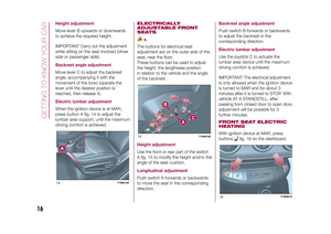 18
18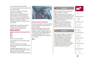 19
19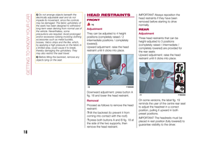 20
20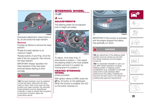 21
21 22
22 23
23 24
24 25
25 26
26 27
27 28
28 29
29 30
30 31
31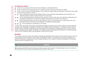 32
32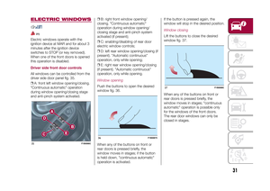 33
33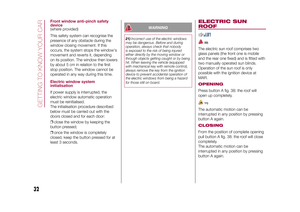 34
34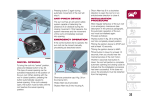 35
35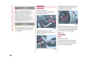 36
36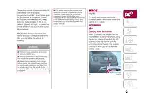 37
37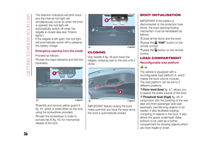 38
38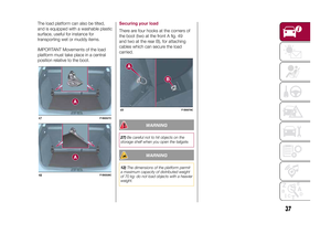 39
39 40
40 41
41 42
42 43
43 44
44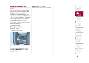 45
45 46
46 47
47 48
48 49
49 50
50 51
51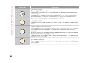 52
52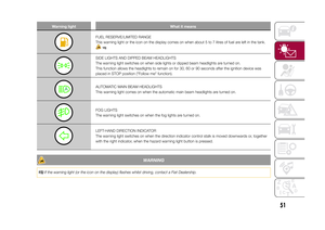 53
53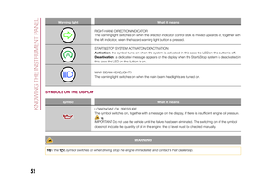 54
54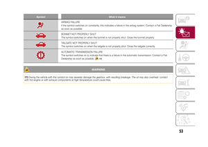 55
55 56
56 57
57 58
58 59
59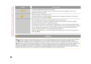 60
60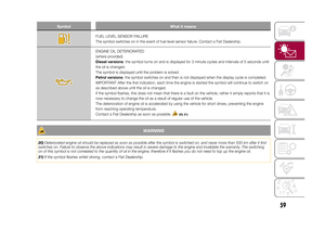 61
61 62
62 63
63 64
64 65
65 66
66 67
67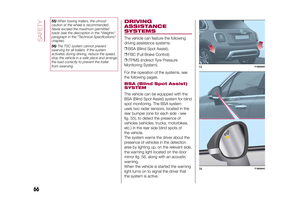 68
68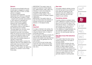 69
69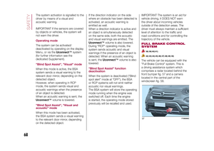 70
70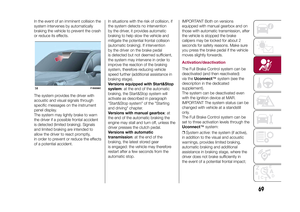 71
71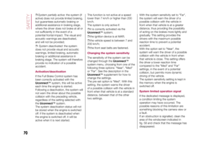 72
72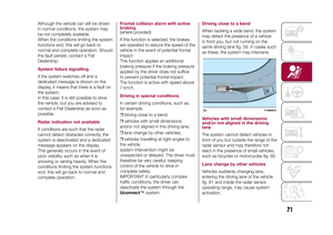 73
73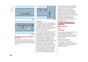 74
74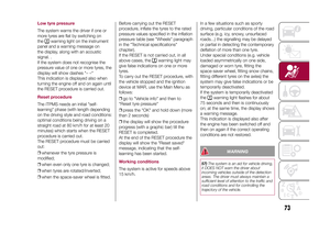 75
75 76
76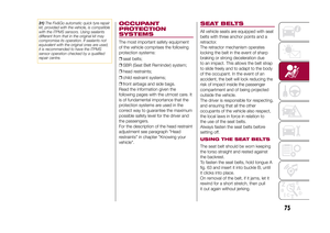 77
77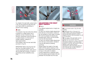 78
78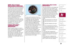 79
79 80
80 81
81 82
82 83
83 84
84 85
85 86
86 87
87 88
88 89
89 90
90 91
91 92
92 93
93 94
94 95
95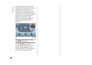 96
96 97
97 98
98 99
99 100
100 101
101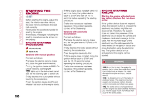 102
102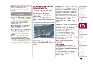 103
103 104
104 105
105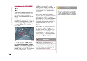 106
106 107
107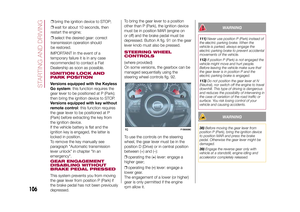 108
108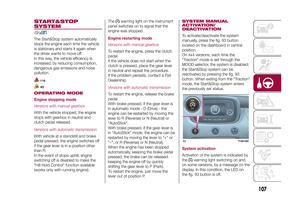 109
109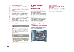 110
110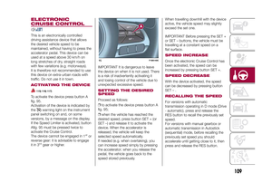 111
111 112
112 113
113 114
114 115
115 116
116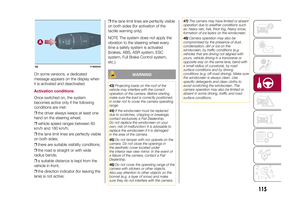 117
117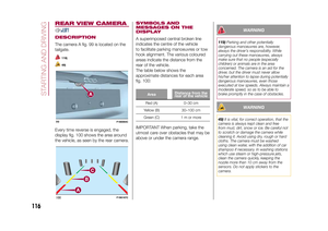 118
118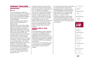 119
119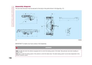 120
120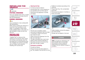 121
121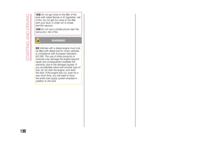 122
122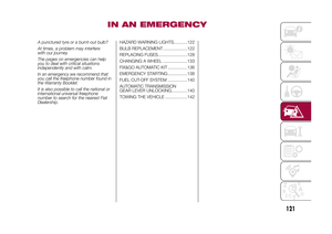 123
123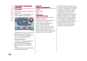 124
124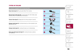 125
125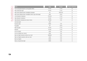 126
126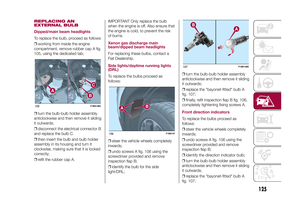 127
127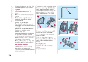 128
128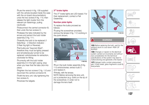 129
129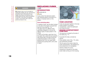 130
130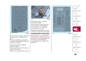 131
131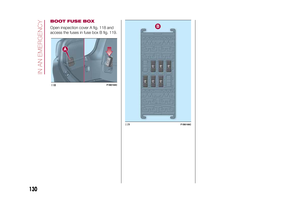 132
132 133
133 134
134 135
135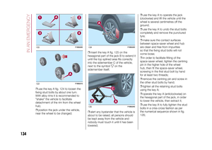 136
136 137
137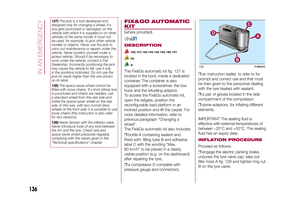 138
138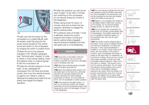 139
139 140
140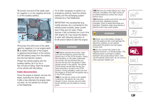 141
141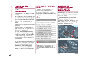 142
142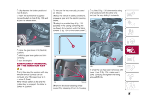 143
143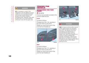 144
144 145
145 146
146 147
147 148
148 149
149 150
150 151
151 152
152 153
153 154
154 155
155 156
156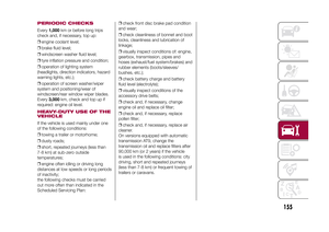 157
157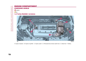 158
158 159
159 160
160 161
161 162
162 163
163 164
164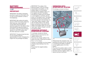 165
165 166
166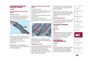 167
167 168
168 169
169 170
170 171
171 172
172 173
173 174
174 175
175 176
176 177
177 178
178 179
179 180
180 181
181 182
182 183
183 184
184 185
185 186
186 187
187 188
188 189
189 190
190 191
191 192
192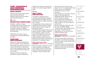 193
193 194
194 195
195 196
196 197
197 198
198 199
199 200
200 201
201 202
202 203
203 204
204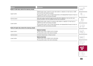 205
205 206
206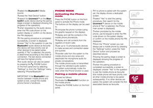 207
207 208
208 209
209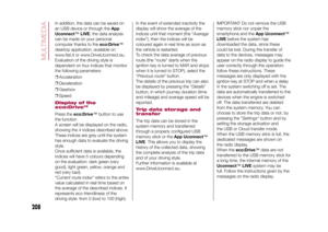 210
210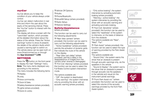 211
211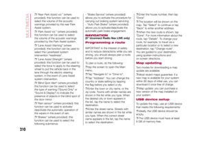 212
212 213
213 214
214 215
215 216
216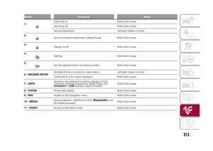 217
217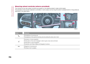 218
218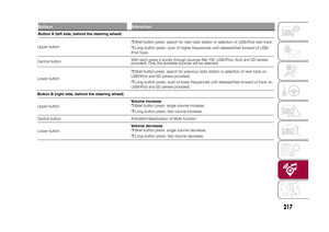 219
219 220
220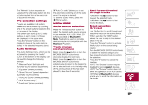 221
221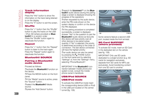 222
222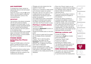 223
223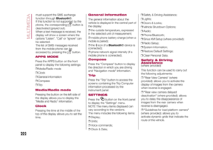 224
224 225
225 226
226 227
227 228
228 229
229 230
230 231
231 232
232 233
233 234
234 235
235 236
236 237
237 238
238 239
239