Page 129 of 240

❒use the wrench A fig. 109 supplied
with the vehicle (located inside the case
with the on-board documentation),
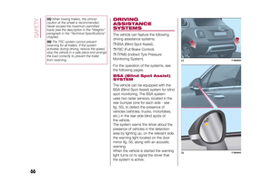
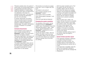
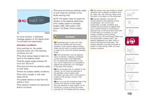
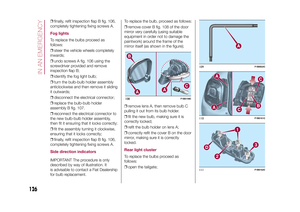
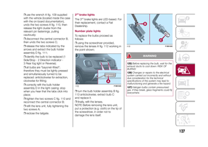
undo the two screws A fig. 110, then
release the light cluster from the
relevant pin fastenings, pulling
cautiously;
❒disconnect the central connector B,
then undo the two screws C;
❒release the tabs indicated by the
arrows and extract the bulb holder
assembly D fig. 111;
❒identify the bulb to be replaced (1
Side/Stop - 2 Direction indicator -
3 Rear fog light or Reverse);
❒all bulbs are "bayonet-fitted";
therefore they must be lightly pressed
and simultaneously turned to be
replaced: anticlockwise for extraction,
clockwise for fitting;
❒correctly refit the bulb holder
assembly D in the light casing; stop
when you hear that the tabs click into
place;
❒tighten the two screws C fig. 110 and
reconnect the central connector B;
❒refit the lens unit, fully tightening the
two screws A;
❒reclose the tailgate.
3rd
brake lights
The 3
rd
brake lights are LED-based. For
their replacement, contact a Fiat
Dealership.
Number plate lightsTo replace the bulbs proceed as
follows:
❒using the screwdriver provided,
remove the lenses A fig. 112 working in
the point shown;
❒turn the bulb holder assembly B fig.
113 anticlockwise, extract bulb C
and replace it.
❒finally, refit the lenses.
NOTE Before removing the lens unit,
put a protection (e.g. cloth) on the tip of
the screwdriver, in order not to
damage the lens itself.
WARNING
125)Before replacing the bulb, wait for the
exhaust ducts to cool down: RISK OF
BURNS!
126)Changes or repairs to the electrical
system carried out incorrectly and without
due consideration for the technical
specifications of the system may lead to
malfunctioning and generate a fire hazard.
127)Halogen bulbs contain pressurised
gas. If they break, glass fragments could fly
everywhere.
112
F1B0153C
113
F1B0154C
127
15-12-2014 8:23 Pagina 127
Page 130 of 240

WARNING
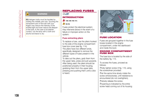
51)Halogen bulbs must be handled by
holding the metallic part only. Touching the
transparent part of the bulb with your
fingers may reduce the intensity of the
emitted light and even reduce the lifespan
of the bulb. In the case of accidental
contact, rub the lamp with a cloth and
alcohol and leave to dry.
REPLACING FUSESINTRODUCTION
128) 129) 130) 131)52) 53)
Fuses protect the electrical system:
they intervene (blow) in the event of a
failure or improper action on the
system.Fuse extracting pliersTo replace a fuse, use the pliers hooked
to the side of the engine compartment
fuse box cover (see fig. 114).
The pliers have two different ends,
specifically designed to remove the
different types of fuses present in the
vehicle.
To take out the pliers, grab them from
the upper tabs, press and pull upwards.
After being used, the pliers should be
positioned properly in their housing,
grabbing them from the upper tabs,
pressing and pushing them until a click
is heard.
FUSE LOCATIONFuses are grouped together in the fuse
boxes located in the engine
compartment, under the dashboard
and inside the boot.ENGINE COMPARTMENT
FUSE BOXThe fuse box is located by the side of
the battery fig. 115.
To access the fuses, proceed as
follows:
❒fully tighten screw A fig. 116, using
the screwdriver provided;
❒at the same time slowly rotate the
screw anticlockwise, until resistance is
encountered (do not overtighten);
❒slowly release the screw;
❒opening is indicated by the entire
screw head coming out of its housing;114
F1B0187C
128
IN AN EMERGENCY
15-12-2014 8:23 Pagina 128
Page 131 of 240
❒remove cover B, sliding it upwards on
the side guides, as indicated in the
figure.
The number identifying the electrical
component corresponding to each fuse
is shown on the cover.
Once the fuse has been replaced,
proceed as follows:
❒correctly refit the cover B in the side
guides of the casing;
❒slide it down completely from the top;❒fully tighten screw A, using the
screwdriver provided;
❒at the same time slowly rotate the
screw clockwise, until resistance is
encountered (do not overtighten);
❒slowly release the screw;
❒closure is indicated by the securing
of the entire screw head in its housing.
DASHBOARD FUSE BOXThe fuse box fig. 117 is located near
the left side of the steering column and
the fuses can be accessed easily from
the lower part of the dashboard.
For fuse replacement, contact a Fiat
Dealership.
115
F1B0191C
116
F1B0190C
117
F1B0193C
129
15-12-2014 8:23 Pagina 129
Page 132 of 240
BOOT FUSE BOXOpen inspection cover A fig. 118 and
access the fuses in fuse box B fig. 119.118
F1B0194C
119
F1B0195C
130
IN AN EMERGENCY
15-12-2014 8:23 Pagina 130
Page 133 of 240
ENGINE COMPARTMENT FUSE BOXUSERSFUSE AMPEREHornF10 10
Power supply for cigar lighter/power socket F84 20
.
DASHBOARD FUSE BOXUSERSFUSE AMPEREFront electric window (passenger side) F33 20
Front electric window (driver side) F34 20
Supply forUconnect
™
system, Climate Control system, Electric
door mirror folding, EOBD system, USB port/AUX socket, rear
side roof lights (versions with sun roof)F36 15
Dead Lock device (Driver side door unlocking for versions/
markets, where provided)/Door unlocking/Central locking/Electric
tailgate unlockingF38 20
Rear left electric window F47 20
Rear right electric window F48 20
131
15-12-2014 8:23 Pagina 131
Page 134 of 240

BOOT FUSE BOXNOTE The configuration of the boot may vary in accordance with the equipment on the vehicle.Fuse box BUSERSFUSE AMPEREHI-FI system F2 20
Electric sun roof F3 20
Front seat electric lumbar adjustment (driver guide) F4 7.5
Electric front seat adjustment (driver side) F5 30
Electric front seat adjustment (driver side and passenger side) F6 7.5
Electric front seat lumbar adjustment (driver side and passenger
side)F7 30
WARNING
128)If the fuse blows again contact a Fiat Dealership.
129)Never replace a fuse with another with a higher amp rating; DANGER OF FIRE
130)If a fuse NOT described on this page and on the previous one blows, contact a Fiat Dealership.
131)Before replacing a fuse, make sure that the ignition device has been taken to STOP, that the ignition key, if mechanical, has been
removed and that all the other devices are switched off and/or deactivated.
WARNING
52)Never replace a blown fuse with metal wires or other material.
53)If it is necessary to wash the engine compartment, take care not to directly hit the fuse box and the window wiper motor with the water
jet.
132
IN AN EMERGENCY
15-12-2014 8:23 Pagina 132
Page 135 of 240

CHANGING A WHEELJACKPlease note that:
❒the weight of the jack is 2.8 kg;
❒The jack requires no adjustment;
❒the jack cannot be repaired and in
the event of a fault it must be replaced
by another original one;
❒No tool other than its cranking device
may be fitted on the jack.CHANGING PROCEDURE
132) 133) 134) 135) 136) 137) 138) 139)
Proceed as follows:
❒stop the vehicle in a position that is
not dangerous for oncoming traffic
where you can change the wheel safely.
The ground should be flat if possible,
and sufficiently firm;
❒stop the engine, engage the hazard
warning lights and the electric parking
brake;
❒engage first gear or reverse or, for
versions with automatic transmission,
move the lever to position P (Park);
❒wear the reflective safety jacket
(compulsory by law in certain countries)
before getting out of the vehicle;❒open the boot and position the
reconfigurable load platform in
an inclined position (see "Boot" in the
"Knowing your vehicle" chapter);
❒take the tool bag provided, which is
secured to the boot cover with specific
fastenings; it contains fig. 120: jack
A; screwdriver B; adaptor C for
refuelling in the event of an emergency;
pin D for centring the wheel (where
provided, to be used in the spare wheel
fitting procedure); special anti-theft
nut E (where provided, to be used in
the wheel stud bolt fitting/removal
procedure); chock F for blocking the
wheels and the vehicle; tow hook
G; key H for the wheel stud bolts and
the jack; Allen key I for emergency
operation of the sun roof (where
provided);
❒raise the mat A fig. 121 and take the
space-saver wheel B;
❒bring the space-saver wheel and the
tool bag near the wheel to be replaced;
❒take the chock A fig. 122 and fold it
out as shown in the diagram;
❒place the chock A on the wheel
diagonally opposite the one to be
replaced (see fig. 123) to prevent the
vehicle from moving irregularly when it
is lifted from the ground;
120
F1B0218C
121
F1B0219C
133
15-12-2014 8:23 Pagina 133
Page 136 of 240

❒use the key A fig. 124 to loosen the
fixing stud bolts by about one turn.
With alloy rims it is recommended to
"shake" the vehicle to facilitate
detachment of the rim from the wheel
hub;
❒position the jack under the vehicle,
near the wheel to be changed;❒insert the key A fig. 125 on the
hexagonal part of the jack B to extend it
until the top splined area fits correctly
into the sidemember C of the vehicle,
next to the symbol
on the
sidemember itself;
❒alert any bystander that the vehicle is
about to be raised; all persons should
be kept away from the vehicle and
nobody must touch it until it has been
lowered;❒use the key A to operate the jack
(clockwise) and lift the vehicle until the
wheel is several centimetres off the
ground;
❒use the key A to undo the stud bolts
completely and remove the punctured
tyre;
❒make sure the contact surfaces
between space-saver wheel and hub
are clean and free from impurities
so that the fixing stud bolts will not
come loose;
❒in order to facilitate fitting of the
space-saver wheel, tighten the centring
pin in the higher hole of the wheel
hub, then fit the space-saver wheel,
screwing in the first stud bolt by hand
for at least two threads;
❒remove the centring pin and screw in
the other stud bolts by hand;
❒tighten all the retaining stud bolts
using the key A;
❒operate the key A (anticlockwise) on
the hexagonal part of the jack, in order
to lower the vehicle, then extract it;
❒use the key A to fully tighten the stud
bolts in a criss-cross fashion as per
the numerical sequence shown in fig.
126;
122
F1B0220C
123
F1B0221C
124
F1B0223C
125
F1B0224C
134
IN AN EMERGENCY
15-12-2014 8:23 Pagina 134