Page 289 of 726
This outlet can power cellular phones, electronics and
other low power devices requiring power up to
150 Watts. Certain high-end video games, such as Play-
station3 and XBox360 will exceed this power limit, as will
most power tools.
The power inverter is designed with built-in overload
protection. If the power rating of 150 Watts is exceeded,
the power inverter will automatically shut down. Once
the electrical device has been removed from the outlet,
the inverter should automatically reset. If the power
rating exceeds approximately 170 Watts, the power in-
verter may have to be reset manually. To reset the
inverter manually push the power inverter button OFF
and ON. To avoid overloading the circuit, check the
power ratings on electrical devices prior to using the
inverter.
WARNING!
To avoid serious injury or death:
•Do not insert any objects into the receptacles.
•Do not touch with wet hands.
•Close the lid when not in use.
•If this outlet is mishandled, it may cause an electric
shock and failure.
CUPHOLDERS
There are cupholders located throughout the interior. All
liners are removable for cleaning. Pull the flexible liner
from the cupholder drawer or tray starting at one edge
for easy removal. Refer to “Cleaning The Instrument
Panel Cupholders” in “Maintaining Your Vehicle” for
further information.
3
UNDERSTANDING THE FEATURES OF YOUR VEHICLE 287
Page 302 of 726
3. Align the console until the front anchor cup plug hole
is centered on the winch hole.
4. Reinstall the clip first and then while pushing down-
ward on the console with slight pressure, reinstall the
cover plug.
5. Pull up on the console to be sure it is firmly latched.
WARNING!
In an accident, serious injury could result if the
removable floor console is not properly installed.
Always be sure the removable floor console is fully
latched.
Premium Console — If Equipped
The three-compartment console with sliding storage bin,
sliding upper tray with storage and large console storage
bin offers multiple configurations.
•Four cupholders with dishwasher safe liners for clean-
ing. The cupholders can accept plastic bottles, large
cups or mugs with handles
•Top tray storage
•Upper storage bin can hold nine regular or 18 thin CDs
or other items
•Large console center storage will store headphones for
the available rear DVD entertainment system or other
items
300 UNDERSTANDING THE FEATURES OF YOUR VEHICLE
Page 303 of 726
•12 Volt DC power outlet provides continuous power
inside the console for cell phones or other electronics
•Rear occupant accessible
•Multiple adjustments
•Removable from vehicle for additional floor space
The top and center console sections slide forward and
rearward to provide added user comfort. A one-piece cup
holder insert for both cavities can easily be removed for
cleaning. The cupholders will also accommodate large
size cups and 20 oz (.6 L) bottles.
Position 1 shows the console closed with four cupholders
and a convenient storage tray.
Console Position 1
3
UNDERSTANDING THE FEATURES OF YOUR VEHICLE 301
Page 318 of 726
▫Units..............................350
▫Vehicle Info (Customer Information Features) . .350
▫Messages #..........................351
▫Keyless Enter-N-Go™ Display — If Equipped . .351
▫Compass / Temperature Display..........352
▫Compass Variance.....................354
▫TURN MENU OFF....................354
▫Customer-Programmable Features
(System Setup).......................354
!Uconnect® 730N/430/430N CD/DVD/HDD/NAV
— IF EQUIPPED.......................362
▫Operating Instructions (Voice Command System) —
If Equipped..........................362
▫Operating Instructions (Uconnect® Phone) — If
Equipped...........................362
!Uconnect® 130........................362
▫Operating Instructions — Radio Mode......363
▫Operation Instructions — CD MODE For CD And
MP3 Audio Play......................366
▫Notes On Playing MP3 Files.............368
▫Operation Instructions — Auxiliary Mode . . . .371
!Uconnect® 130 WITH SATELLITE RADIO.....372
▫Operating Instructions — Radio Mode.......372
▫Operation Instructions — CD MODE For CD And
MP3 Audio Play......................378
▫Notes On Playing MP3 Files.............380
▫LIST Button — CD Mode For MP3 Play......383
316 UNDERSTANDING YOUR INSTRUMENT PANEL
Page 319 of 726
▫INFO Button — CD Mode For MP3 Play.....383
▫Uconnect® (Satellite Radio) — If Equipped . . .384
▫Operating Instructions (Uconnect® Phone) — If
Equipped...........................389
!SETTING THE ANALOG CLOCK...........389
!iPod®/USB/MP3 CONTROL — IF EQUIPPED . .390
▫Connecting The iPod® Or External USB
Device.............................391
▫Using This Feature.....................392
▫Controlling The iPod® Or External USB Device
Using Radio Buttons...................392
▫Play Mode..........................392
▫List Or Browse Mode...................394
▫Bluetooth® Streaming Audio (BTSA).......396
!Uconnect® MULTIMEDIA — VIDEO
ENTERTAINMENT SYSTEM (VES™) — IF
EQUIPPED...........................397
▫Getting Started.......................397
▫Blu-ray™ Disc Player...................398
▫Play Video Games.....................400
▫Listen To An Audio Source On Channel 2 While A
Video Is Playing On Channel 1............403
▫Dual Video Screen.....................405
▫Play A DVD Using The Touchscreen Radio . . .405
▫Play A DVD Using The VES™ Player — If
Equipped...........................408
▫Play A Blu-ray™ Disc Using The Blu-ray™
Player — If Equipped..................412
4
UNDERSTANDING YOUR INSTRUMENT PANEL 317
Page 320 of 726
▫Listen To An Audio Source While A Video Is
Playing.............................414
▫Important Notes For Dual Video Screen
System.............................416
▫VES™ Remote Control — If Equipped.......417
▫Blu-ray™ Player Remote Control — If
Equipped...........................420
▫Remote Control Storage.................422
▫Locking The Remote Control.............423
▫Replacing The Remote Control Batteries......423
▫Headphones Operation.................424
▫Blu-ray™ Headphones Operation..........425
▫Controls............................426
▫Replacing The Headphone Batteries.........427
▫Unwired® Stereo Headphone Lifetime Limited
Warranty...........................427
▫System Information....................428
▫Shared Modes........................428
▫Information Mode Display...............430
▫Numeric Keypad Menu.................430
▫Station List Menu.....................431
▫Disc Menu..........................432
▫Display Settings.......................432
▫Listening To Audio With The Screen Closed . . .433
▫Disc Formats.........................433
▫Display.............................439
▫Product Agreement....................443
318 UNDERSTANDING YOUR INSTRUMENT PANEL
Page 321 of 726
!STEERING WHEEL AUDIO CONTROLS — IF
EQUIPPED...........................447
▫Radio Operation......................447
▫CD Player...........................448
!CD/DVD/Blu-ray™ Disc MAINTENANCE . . . .448
!RADIO OPERATION AND MOBILE PHONES . .449
▫General Information...................449
!CLIMATE CONTROLS...................449
▫Manual Heating And Air Conditioning
System — If Equipped.................450
▫Rear Manual Climate Control — If Equipped . .455
▫Automatic Temperature Control (ATC) — If
Equipped...........................457
▫Operating Tips.......................4694
UNDERSTANDING YOUR INSTRUMENT PANEL 319
Page 355 of 726
4. Push and release the SELECT button to start the
calibration. The “CAL” indicator will be displayed in
the EVIC.
5. Complete one or more 360–degree turns (in an area
free from large metal or metallic objects) until the
“CAL” indicator turns off. The compass will now
function normally.
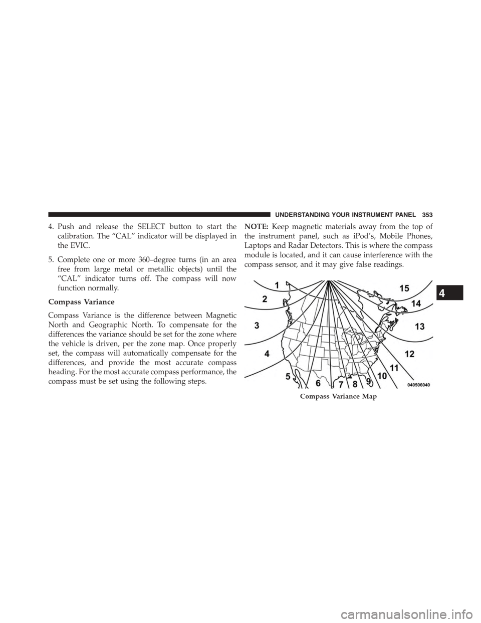
Compass Variance
Compass Variance is the difference between Magnetic
North and Geographic North. To compensate for the
differences the variance should be set for the zone where
the vehicle is driven, per the zone map. Once properly
set, the compass will automatically compensate for the
differences, and provide the most accurate compass
heading. For the most accurate compass performance, the
compass must be set using the following steps.
NOTE:Keep magnetic materials away from the top of
the instrument panel, such as iPod’s, Mobile Phones,
Laptops and Radar Detectors. This is where the compass
module is located, and it can cause interference with the
compass sensor, and it may give false readings.
Compass Variance Map
4
UNDERSTANDING YOUR INSTRUMENT PANEL 353