Page 25 of 220

The OCS determines the front passenger’s most probable classification. If an occupant in the
front passenger seat is seated improperly, the occupant may provide an output signal to the OCS
that is different from the occupant’s properly seated weight input, for example:
The Air Bag Warning Light
will turn on
whenever the OCS is unable to classify the
front passenger seat status. A malfunction in
the OCS may affect the operation of the air
bag system.
If the Air Bag Warning Light
does not
come on, or stays on after you start the vehicle,
or it comes on as you drive, take the vehicle to
an authorized dealer for service immediately.
The passenger seat assembly contains critical
components that may affect the Passenger
Advanced Front Air Bag inflation. In order for
the OCS to properly classify the seated weight
of a front seat passenger, the OCS compo-
nents must function as designed.
Do not make any modifications to the front
passenger seat components, assembly, or to
the seat cover. If the seat, trim cover, or cushion
needs service for any reason, take the vehicle to
your authorized dealer. Only Chrysler Group
LLC approved seat accessories may be used.
The following requirements must be strictly
followed:
• Do not modify the front passenger seat as- sembly or components in any way.
• Do not use prior or future model year seat covers or cushions not designated by
Chrysler Group LLC for the specific model
being repaired. Always use the correct seat
cover and cushion specified for the vehicle.
• Do not replace the seat cover or cushion with an aftermarket seat cover or cushion.
• Do not add a secondary seat cover or mat.
• At no time should any Supplemental Re- straint System (SRS) component or SRS re-
lated component or fastener be modified or
replaced with any part except those which are approved by Chrysler Group LLC.
Not Seated Properly
Not Seated Properly
Not Seated Properly
Not Seated Properly
GETTING STARTED
23
Page 26 of 220

Supplemental Knee Air Bags
This vehicle is equipped with a Supplemental Driver Knee Air Bag mounted in the instrument
panel below the steering column and a Supplemental Passenger Knee Air Bag mounted in the
instrument panel below the glove compartment. The Supplemental Knee Air Bags provide
enhanced protection during a frontal impact by working together with the seat belts, pretension-
ers, and Advanced Front Air Bags.
WARNING!
• Relying on the air bags alone could lead to more severe injuries in a collision. The air bagswork with your seat belt to restrain you properly. In some collisions, the air bags won't
deploy at all. Always wear your seat belts even though you have air bags.
• Being too close to the steering wheel or instrument panel during Advanced Front Air Bag
deployment could cause serious injury, including death. Air bags need room to inflate. Sit
back, comfortably extending your arms to reach the steering wheel or instrument panel.
• No objects should be placed over or near the air bag on the instrument panel or steering
wheel because any such objects could cause harm if the vehicle is in a collision severe
enough to cause the air bag to inflate.
Supplemental Side Air Bags
• This vehicle is equipped with Supplemental Seat-Mounted Side Air Bags (SABs) located in
the outboard side of the front seats. The SABs are marked with a SRS AIRBAG or AIRBAG
label sewn into the outboard side of the seats.
• This vehicle is equipped with Supplemental Side Air Bag Inflatable Curtains (SABICs) located above the side windows. The trim covering the SABICs is labeled SRS AIRBAG or AIRBAG.
The SABICs may help reduce the risk of partial or complete ejection of vehicle occupants
through side windows in certain side impact events.
• The SABICs and SABs (“Side Air Bags”) are designed to activate in certain side impacts and certain rollover events. The Occupant Restraint Controller (“ORC”) determines whether the
deployment of the Side Air Bags in a particular side impact or rollover event is appropriate,
based on the severity and type of collision. Vehicle damage by itself is not a good indicator of
whether or not Side Air Bags should have deployed.
GETTING STARTED
24
Page 27 of 220

WARNING!
• Side Air Bags need room to inflate. Do not lean against the door or window. Sit upright inthe center of the seat.
• Being too close to the Side Air Bags during deployment could cause you to be severely
injured or killed.
• Relying on the Side Air Bags alone could lead to more severe injuries in a collision. The
Side Air Bags work with your seat belt to restrain you properly. In some collisions, Side Air
Bags won’t deploy at all. Always wear your seat belt even though you have Side Air Bags.
• This vehicle is equipped with left and right Supplemental Side Air Bag Inflatable Curtains
(SABICs). Do not stack luggage or other cargo up high enough to block the deployment
of the SABICs. The trim covering above the side windows where the SABIC and its
deployment path are located should remain free from any obstructions.
• This vehicle is equipped with SABICs. In order for the SABICs to work as intended, do not
install any accessory items in your vehicle which could alter the roof. Do not add an
aftermarket sunroof to your vehicle. Do not add roof racks that require permanent
attachments (bolts or screws) for installation on the vehicle roof. Do not drill into the roof
of the vehicle for any reason.
• Do not use accessory seat covers or place objects between you and the Side Air Bags; the
performance could be adversely affected and/or objects could be pushed into you,
causing serious injury.
CHILD RESTRAINTS
Children 12 years or younger should ride properly buckled up in a rear seat, if available. According to
crash statistics, children are safer when properly restrained in the rear seats rather than in the front.
Every state in the United States and all Canadian provinces require that small children ride in
proper restraint systems. This is the law, and you can be prosecuted for ignoring it.
NOTE:
• For additional information, refer to www.Seatcheck.org or call 1-866-SEATCHECK.
• Canadian residents should refer to Transport Canada’s website for additional information:http://www.tc.gc.ca/eng/motorvehiclesafety/safedrivers-childsafety-index-53.htm
LATCH — Lower Anchors And Tethers For CHildren
Your vehicle is equipped with the child restraint anchorage system called LATCH, which stands
for Lower Anchors and Tethers for CHildren.
The rear outboard seating positions have lower anchors and top tether anchors. The rear center
seating position has a top tether anchor only.
LATCH System Weight Limit
You may use the LATCH anchorage system until the combined weight of the child and the child
restraint is 65 lbs (29.5 kg). Use the seat belt and tether anchor instead of the LATCH system
once the combined weight is more than 65 lbs (29.5 kg).
GETTING STARTED
25
Page 28 of 220

Locating The LATCH Lower Anchorages
The lower anchorages are round bars that
are found at the rear of the seat cushion where
it meets the seatback, below the anchorage
symbols on the seatback. They are just visible
when you lean into the rear seat to install the
child restraint. You will easily feel them if you
run your finger along the gap between the
seatback and seat cushion.
Locating The Tether Anchorages
In addition, there are tether strap anchor-
ages behind each rear seating position located
in the panel between the rear seatback and the
rear window. These tether strap anchorages are
under a plastic cover with the tether anchorage
symbol on it.
Center Seat LATCH
Do not install child restraints with rigid lower attachments in the center seating position. Only
install this type of child restraint in the outboard seating positions. Child restraints with flexible,
webbing mounted lower attachments can be installed in any rear seating position. In the center
position, the inner anchorages are 17.7 inches (450 mm) apart.
Installing The Child Restraint Using The LATCH Lower Anchors
NOTE:
Never “share” a LATCH anchorage with two or more child restraints.
1. Loosen the adjusters on the lower straps and on the tether strap of the child seat so that you can more easily attach the hooks or connectors to the vehicle anchorages.
2. Attach the lower hooks or connectors of the child restraint to the lower anchorages in the selected seating position.
3. If the child restraint has a tether strap, connect it to the top tether anchorage. See below for directions to attach a tether anchor.
4. Tighten all of the straps as you push the child restraint rearward and downward into the seat. Remove slack in the straps according to the child restraint manufacturer’s instructions.
5. Test that the child restraint is installed tightly by pulling back and forth on the child seat at the belt path. It should not move more than 1 inch (25.4 mm) in any direction.
Lower Anchors
GETTING STARTED
26
Page 29 of 220
 that is designed to keep")
Installing The Child Restraint Using The Vehicle Seat Belts
The seat belts in the passenger seating positions are equipped with a Switchable Automatic
Locking Retractor (ALR) that is designed to keep the lap portion of the seat belt tight around the
child restraint. Any seat belt system will loosen with time, so check the belt occasionally, and pull
it tight if necessary.
Tether Weight Limit
Always use the tether anchor when using the seat belt to install a forward facing child restraint, up
to the recommended weight limit of the child restraint.
To Install A Child Seat Using An ALR:
1. Pull enough of the seat belt webbing from the retractor to pass it through the belt path of thechild restraint. Do not twist the belt webbing in the belt path.
2. Slide the latch plate into the buckle until you hear a “click.”
3. Pull on the webbing to make the lap portion tight against the child seat.
4. To lock the seat belt, pull down on the shoulder part of the belt until you have pulled all the seat belt webbing out of the retractor. Then, allow the webbing to retract back into the retractor. As
the webbing retracts, you will hear a clicking sound. This means the seat belt is now in the
Automatic Locking mode.
5. Try to pull the webbing out of the retractor. If it is locked, you should not be able to pull out any webbing. If the retractor is not locked, repeat the last step.
6. Finally, pull up on any extra webbing to tighten the lap portion around the child restraint while you push the child restraint rearward and downward into the vehicle seat.
7. If the child restraint has a top tether strap and the seating position has a top tether anchorage, connect the tether strap to the anchorage and tighten the tether strap. See below for
directions to attach a tether anchor.
8. Test that the child restraint is installed tightly by pulling back and forth on the child seat at the belt path. It should not move more than 1 inch (25.4 mm) in any direction.
Installing The Top Tether Strap (With Either Lower Anchors Or Vehicle
Seat Belt):
When installing a forward-facing child restraint, always secure the top tether strap, up to the
tether anchor weight limit, whether the child restraint is installed with the lower anchors or the
vehicle seat belt.
Tether Anchorage Installation
1. Rotate or lift the cover to access the anchor directly behind the seat where you are placing thechild restraint.
2. Route the tether strap to provide the most direct path for the strap between the anchor and the child seat.
GETTING STARTED
27
Page 30 of 220

3. If your vehicle is equipped with adjustable rear head restraints, raise the head restraint, andwhere possible, route the tether strap under the head restraint and between the two posts. If
not possible, lower the head restraint and pass the tether strap around the outboard side of the
head restraint.
4. Attach the tether strap hook of the child restraint to the top tether anchorage and remove slack in the tether strap according to the child restraint manufacturer’s instructions.
HEAD RESTRAINTS
Head restraints are designed to reduce the risk of injury by restricting head movement in the
event of a rear impact. Head restraints should be adjusted so that the top of the head restraint is
located above the top of your ear.
WARNING!
The head restraints for all occupants must be properly adjusted prior to operating the vehicle
or occupying a seat. Head restraints should never be adjusted while the vehicle is in motion.
Driving a vehicle with the head restraints improperly adjusted or removed could cause serious
injury or death in the event of a collision.
Reactive Head Restraints — Front Seats
The front driver and passenger seats are equipped with Reactive Head Restraints (RHR). In the
event of a rear impact the RHRs will automatically extend forward minimizing the gap between
the back of the occupants head and the RHR.
The RHRs will automatically return to their normal position following a rear impact. If the RHRs
do not return to their normal position see your authorized dealer immediately.
To raise the head restraint, pull upward on the head restraint. To lower the head restraint, press the
release button, located at the base of the head restraint, and push downward on the head
restraint.
NOTE:
The head restraints should only be removed by qualified technicians, for service purposes only. If
either of the head restraints require removal, see your authorized dealer.
WARNING!
Do not place items over the top of the Reactive Head Restraint, such as coats, seat covers or
portable DVD players. These items may interfere with the operation of the Reactive Head
Restraint in the event of a collision and could result in serious injury or death.
GETTING STARTED
28
Page 31 of 220

Rear Head Restraints
The rear outboard head restraints have three positions UP, MID and DOWN. The center head
restraint has only two positions, Up and Down. When the center seat is being occupied the head
restraint should be in the raised position. When there are no occupants in the center seat the head
restraint can be lowered for maximum visibility for the driver.
To raise the head restraint, pull upward on the head restraint. To lower the head restraint, press the
push button, located at the base of the head restraint, and push downward on the head restraint.
FRONT SEATS
Power Seats
The power seat switches are located on the
outboard side of the front seat cushions.
The power seat switch controls forward, rear-
ward, up and down adjustments.
The recline switch controls the angle of the
seatback.
• Press the switch forward or rearward and theseatback will move in either direction.
The power lumbar switch controls the amount
of lumbar support needed.
• Push the switch forward to increase the lum- bar support.
• Push the switch rearward to decrease the lumbar support.
• Pushing upward or downward on the switch will raise and lower the position of the support.
Memory Seat
The memory seat feature allows you to set two different driver seating positions, driver's outside
mirror, and radio station preset settings. The memory seat buttons are located on the driver's
door panel.
To set a memory position:
1.
Cycle the vehicles ignition to the ON position.
2. Adjust all memory profile settings.
Power Seat Switches
1 — Power Seat Switch
2 — Recline Switch
3 — Power Lumbar Switch
Memory Seat Buttons
GETTING STARTED
29
Page 32 of 220
 button then press the 1 or 2 button within five seconds. The ElectronicVehicle Information Center (EVIC) or Driver Information Display (DID) will display which
memory position is")
3. Press the S (SET) button then press the 1 or 2 button within five seconds. The ElectronicVehicle Information Center (EVIC) or Driver Information Display (DID) will display which
memory position is being set.
NOTE:
Before programming your RKE transmitters you must select the “Personal Settings Linked To
Fob” feature through the Uconnect® system. Refer to “Uconnect® Settings ” in “Understanding
Your Instrument Panel” in the Owner's Manual on the DVD for further details.
To program a Key Fob to the memory position:
1. Cycle the vehicles ignition to the OFF position.
2. Select the desired memory profile 1 or 2.
3. Press and release the SET button on the memory switch, then within five seconds press and release the button labeled 1 or 2 accordingly. “Memory Profile Set” (1 or 2) will display in the
EVIC/DID.
4. Press and release the LOCK button on the RKE transmitter within 10 seconds.
Easy Entry/Exit Feature
The memory seat has an Easy Entry/Exit feature. This feature provides automatic driver seat
positioning to enhance driver mobility when entering and exiting the vehicle.
NOTE:
The Easy Entry/Exit feature is not enabled when the vehicle is delivered from the factory. The
Easy Entry/Exit feature is enabled (or later disabled) through the programmable features in the
Uconnect® system. Refer to “Uconnect® Settings ” in “Understanding Your Instrument Panel” in
the Owner's Manual on the DVD for further details.
Manual Seat Adjustment
Forward/Rearward
Lift up on the adjusting bar located at the front
of the seat near the floor and release it when
the seat is at the desired position. Then, using
body pressure, move forward and backward on
the seat to be sure that the seat adjusters have
latched.
Recliner
• Lean forward in the seat and lift the recliner lever, then lean back to the desired position
and release the lever.
• Lift the lever to return the seatback to an upright position.
Manual Seat Levers
1 — Adjusting Bar
2 — Height Adjustment
3 — Recliner Lever
GETTING STARTED
30
 1
1 2
2 3
3 4
4 5
5 6
6 7
7 8
8 9
9 10
10 11
11 12
12 13
13 14
14 15
15 16
16 17
17 18
18 19
19 20
20 21
21 22
22 23
23 24
24 25
25 26
26 27
27 28
28 29
29 30
30 31
31 32
32 33
33 34
34 35
35 36
36 37
37 38
38 39
39 40
40 41
41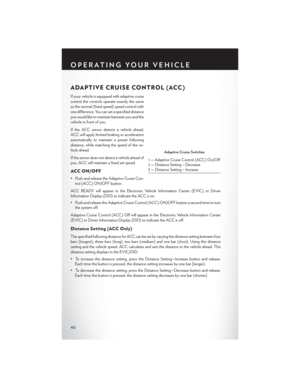 42
42 43
43 44
44 45
45 46
46 47
47 48
48 49
49 50
50 51
51 52
52 53
53 54
54 55
55 56
56 57
57 58
58 59
59 60
60 61
61 62
62 63
63 64
64 65
65 66
66 67
67 68
68 69
69 70
70 71
71 72
72 73
73 74
74 75
75 76
76 77
77 78
78 79
79 80
80 81
81 82
82 83
83 84
84 85
85 86
86 87
87 88
88 89
89 90
90 91
91 92
92 93
93 94
94 95
95 96
96 97
97 98
98 99
99 100
100 101
101 102
102 103
103 104
104 105
105 106
106 107
107 108
108 109
109 110
110 111
111 112
112 113
113 114
114 115
115 116
116 117
117 118
118 119
119 120
120 121
121 122
122 123
123 124
124 125
125 126
126 127
127 128
128 129
129 130
130 131
131 132
132 133
133 134
134 135
135 136
136 137
137 138
138 139
139 140
140 141
141 142
142 143
143 144
144 145
145 146
146 147
147 148
148 149
149 150
150 151
151 152
152 153
153 154
154 155
155 156
156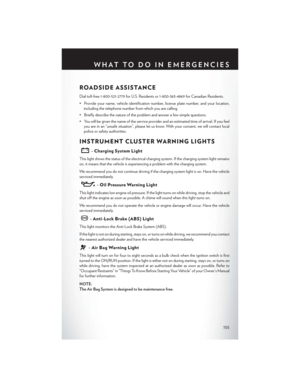 157
157 158
158 159
159 160
160 161
161 162
162 163
163 164
164 165
165 166
166 167
167 168
168 169
169 170
170 171
171 172
172 173
173 174
174 175
175 176
176 177
177 178
178 179
179 180
180 181
181 182
182 183
183 184
184 185
185 186
186 187
187 188
188 189
189 190
190 191
191 192
192 193
193 194
194 195
195 196
196 197
197 198
198 199
199 200
200 201
201 202
202 203
203 204
204 205
205 206
206 207
207 208
208 209
209 210
210 211
211 212
212 213
213 214
214 215
215 216
216 217
217 218
218 219
219