2015 BMW Z4 SDRIVE35IS I car 03
[x] Cancel search: I car 03Page 101 of 289
A loss of tire inflation pressure results in a
change in the handling characteristics, e.g., re‐
duced lane stability during braking, a longer
braking distance and altered self-steering
properties.◀
Final tire failure
Vibrations or loud noises while driving
can indicate the final failure of the tire. Reduce
speed and stop; otherwise, pieces of the tire
could come loose and cause an accident. Do
not continue driving, and contact your service
center.◀
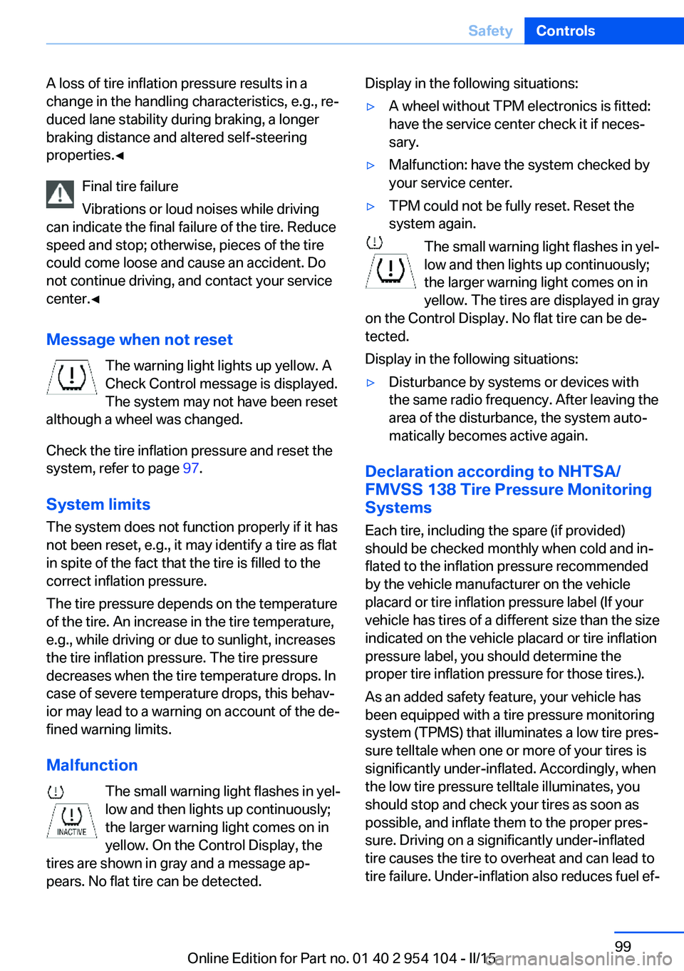
Message when not reset The warning light lights up yellow. A
Check Control message is displayed.
The system may not have been reset
although a wheel was changed.
Check the tire inflation pressure and reset the
system, refer to page 97.
System limits
The system does not function properly if it has
not been reset, e.g., it may identify a tire as flat
in spite of the fact that the tire is filled to the
correct inflation pressure.
The tire pressure depends on the temperature
of the tire. An increase in the tire temperature,
e.g., while driving or due to sunlight, increases
the tire inflation pressure. The tire pressure
decreases when the tire temperature drops. In
case of severe temperature drops, this behav‐
ior may lead to a warning on account of the de‐
fined warning limits.
Malfunction The small warning light flashes in yel‐
low and then lights up continuously;
the larger warning light comes on in
yellow. On the Control Display, the
tires are shown in gray and a message ap‐
pears. No flat tire can be detected.Display in the following situations:▷A wheel without TPM electronics is fitted:
have the service center check it if neces‐
sary.▷Malfunction: have the system checked by
your service center.▷TPM could not be fully reset. Reset the
system again.
The small warning light flashes in yel‐
low and then lights up continuously;
the larger warning light comes on in
yellow. The tires are displayed in gray
on the Control Display. No flat tire can be de‐
tected.
Display in the following situations:
▷Disturbance by systems or devices with
the same radio frequency. After leaving the
area of the disturbance, the system auto‐
matically becomes active again.
Declaration according to NHTSA/
FMVSS 138 Tire Pressure Monitoring
Systems
Each tire, including the spare (if provided)
should be checked monthly when cold and in‐
flated to the inflation pressure recommended
by the vehicle manufacturer on the vehicle
placard or tire inflation pressure label (If your
vehicle has tires of a different size than the size
indicated on the vehicle placard or tire inflation
pressure label, you should determine the
proper tire inflation pressure for those tires.).
As an added safety feature, your vehicle has
been equipped with a tire pressure monitoring
system (TPMS) that illuminates a low tire pres‐
sure telltale when one or more of your tires is
significantly under-inflated. Accordingly, when
the low tire pressure telltale illuminates, you
should stop and check your tires as soon as
possible, and inflate them to the proper pres‐
sure. Driving on a significantly under-inflated
tire causes the tire to overheat and can lead to
tire failure. Under-inflation also reduces fuel ef‐
Seite 99SafetyControls99
Online Edition for Part no. 01 40 2 954 104 - II/15
Page 107 of 289
Driving comfortVehicle equipment
This chapter describes all series equipment as
well as country-specific and special equipment
offered for this model series. Therefore, it also
describes equipment that may not be found in
your vehicle, for instance due to the selected
special equipment or the country version. This
also applies to safety-related functions and
systems.
When using the features and systems descri‐
bed here, adhere to local regulations.
Cruise control The concept
Cruise control is available for use at speeds of
approx. 20 mph/30 km/h and higher. The car
then stores and maintains the speed that you
specify using the lever on the steering column.
In order to maintain the specified speed, the
system brakes the vehicle when the engine
braking effect is insufficient on downhill gradi‐
ents.
Do not use cruise control
Do not use the system if unfavorable
conditions make it impossible to drive at a con‐
stant speed, for instance:▷On curvy roads.▷In heavy traffic.▷On slippery roads, in fog, snow or rain, or
on a loose road surface.
Otherwise, you could lose control of the vehi‐
cle and cause an accident.◀
Manual transmission
You can shift gears while cruise control is acti‐
vated. An indicator lamp notifies you that you
should shift gears when you drive for an ex‐
tended period at very high or very low engine
speeds, or the system is deactivated.
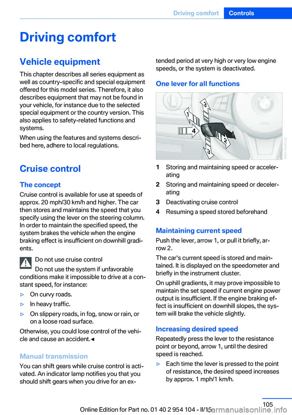
One lever for all functions1Storing and maintaining speed or acceler‐
ating2Storing and maintaining speed or deceler‐
ating3Deactivating cruise control4Resuming a speed stored beforehand
Maintaining current speed
Push the lever, arrow 1, or pull it briefly, ar‐
row 2.
The car's current speed is stored and main‐
tained. It is displayed on the speedometer and briefly in the instrument cluster.
On uphill gradients, it may prove impossible to
maintain the set speed if current engine power
output is insufficient. If the engine braking ef‐
fect is insufficient on downhill slopes, the sys‐
tem will brake the vehicle slightly.
Increasing desired speed
Repeatedly press the lever to the resistance
point or beyond, arrow 1, until the desired
speed is reached.
▷Each time the lever is pressed to the point
of resistance, the desired speed increases
by approx. 1 mph/1 km/h.Seite 105Driving comfortControls105
Online Edition for Part no. 01 40 2 954 104 - II/15
Page 108 of 289
▷Each time the lever is pressed beyond the
resistance point, the desired speed is in‐
creased by up to 5 mph/10 km/h.
The system stores and maintains the speed.
Accelerating using the lever
Accelerating slightly:
Press the lever to the resistance point, arrow 1,
and hold until the desired speed is reached.
Accelerating significantly:
Press the lever beyond the resistance point,
arrow 1, and hold until the desired speed is
reached.
The vehicle accelerates without pressure on
the accelerator pedal. The system stores and
maintains the speed.
Decreasing speed Repeatedly pull the lever to the resistance
point or beyond, arrow 2, until the desired
speed is displayed.
▷Each time the lever is pulled to the resist‐
ance point, the desired speed is decreased
by approx. 1 mph/1 km/h.▷Each time the lever is pulled beyond the
resistance point, the desired speed is re‐
duced by up to 5 mph or 10 km/h until the
minimum speed of 20 mph/30 km/h is ach‐
ieved.
The system stores and maintains the speed.
Interrupting the system
Push the lever upwards or downwards, ar‐
row 3.
The displays in the speedometer change color.
In addition, the system is automatically inter‐
rupted in the following situations:
▷When the brakes are applied.▷In cars with manual transmission, when
gears are shifted very slowly or if neutral is
engaged.▷In cars with Sport automatic transmission,
when transmission position N is engaged.▷When DTC is activated or DSC is deacti‐
vated.▷When DSC or ABS is intervening.
Cruise control is not deactivated by depressing
the accelerator pedal. Once the accelerator
pedal is released, the stored speed is achieved
again and maintained.
Warning light A message appears on the Control
Display.
The warning light comes on, for ex‐
ample, when cruise control has been deacti‐
vated as a result of DSC intervention.
Deactivating the system
▷Press the lever upward or downward twice,
arrow 3.▷Switch off the ignition.
The stored speed is cleared.
Resuming a speed stored beforehand Press the button, arrow 4. The last stored
speed is resumed and maintained.
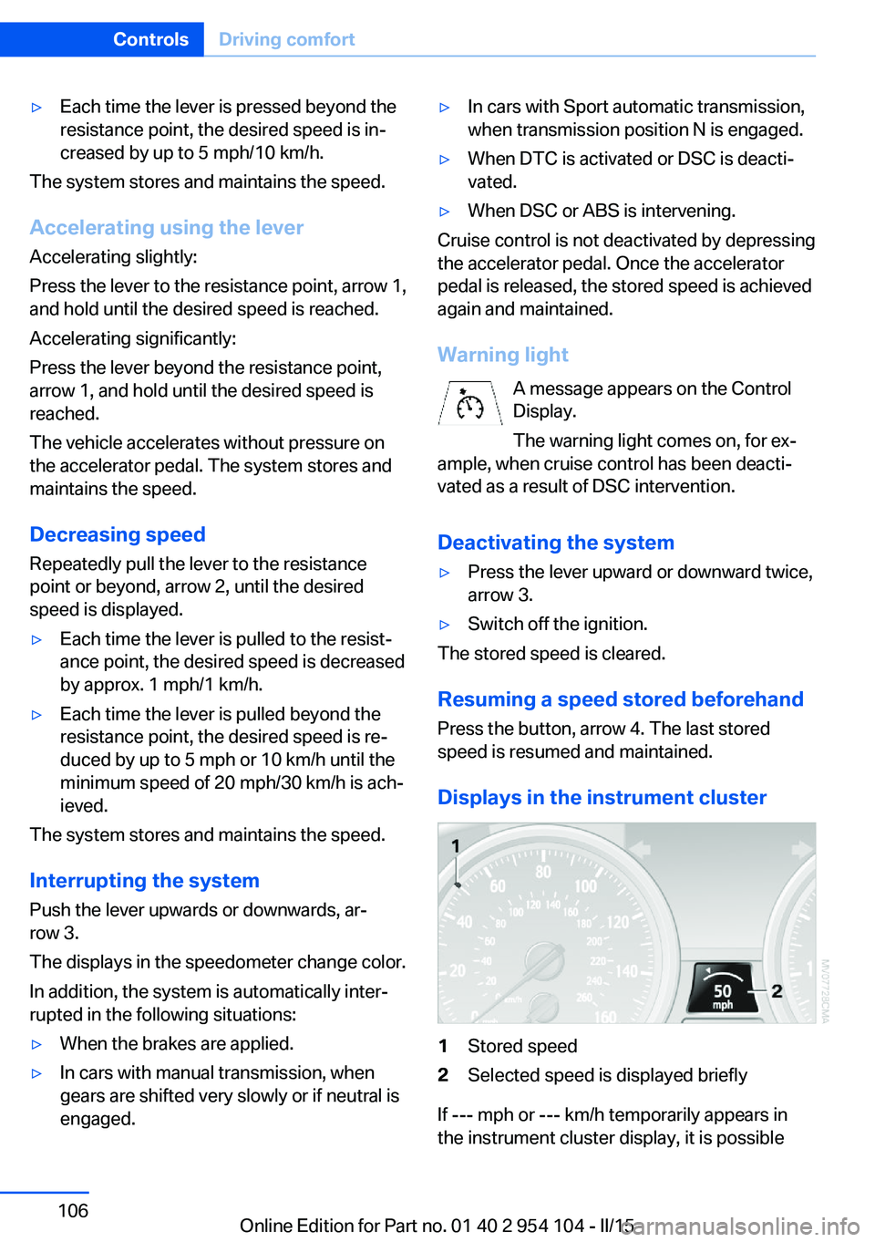
Displays in the instrument cluster
1Stored speed2Selected speed is displayed briefly
If --- mph or --- km/h temporarily appears in
the instrument cluster display, it is possible
Seite 106ControlsDriving comfort106
Online Edition for Part no. 01 40 2 954 104 - II/15
Page 112 of 289

4Air vent: air for the upper body area. The
thumbwheels increase and decrease theair supply continuously; the levers change
the direction of the airflow.5Air vent: air for the knee area, footwell
Air conditioner
1Vent settings2Recirculated air mode3Cooling function4Temperature5Air volume6Rear window defrosterNote
Sufficient ventilation
When remaining in the vehicle for an ex‐
tended period of time, ensure sufficient exter‐
nal ventilation. Do not continuously use recir‐
culated-air mode; otherwise the air quality in
the interior continuously worsens.◀
Climate control functions in detail
Switching the system on/off Press and hold the left button or,
with the blower at its lowest set‐
ting, press the left button. The
blower and air conditioner are completely
switched off and the air supply is cut off.
To switch on the air conditioner, set the de‐
sired air flow rate.Temperature
To increase the temperature, turn
the rotary switch clockwise to‐
wards red. For a lower tempera‐
ture, turn the rotary switch coun‐
terclockwise towards blue.
Switching cooling function on/off The cooling function cools and
dehumidifies the incoming air be‐
fore reheating it as required, according to the
temperature setting. This function is only avail‐
able while the engine is running.
The cooling function helps to prevent conden‐
sation on the windows or to remove it quickly.
Depending on the weather, the windshield may
fog over briefly when the engine is started.
Recirculated air mode If the air outside the car has an un‐
pleasant odor or contains pollu‐Seite 110ControlsClimate110
Online Edition for Part no. 01 40 2 954 104 - II/15
Page 113 of 289

tants, shut off the supply to the interior of the
car temporarily. The system then recirculates
the air currently within the vehicle.
The recirculated air mode can also be acti‐
vated/deactivated, refer to page 14, via a but‐
ton on the steering wheel.
Air volume Press the corresponding button.
The higher the rate, the more ef‐
fective the heating or cooling will
be.
The air flow rate may be reduced or the blower
may be switched off entirely to save on battery
power.
Vent settings Direct the flow of air to the win‐
dows
, to the upper body area
, or to the knee area and foot‐
well
. Intermediate positions
are possible. In the 6 o'clock posi‐
tion, a small amount of air is also directed to‐
ward the windows to keep them from fogging
over.
Defrosting windows and removing
condensation
1Air distribution 1 in position .2Deactivate recirculated air mode 2.3Switch on cooling function 3.4Temperature 4 to the right, red.5Set the air flow rate 5 to the maximum
level.6Switch on the rear window defroster 6 to
defrost the rear window
.
Rear window defroster
The defroster switches off auto‐
matically after a certain time or
when the hardtop is opened.
Microfilter
The microfilter removes dust and pollen from
the incoming air. The microfilter is changed by
your service center during routine mainte‐
nance work.
Ventilation
1Use the lever to change the direction of the
air flow2Use the thumbwheels to smoothly open
and close the air vents
Ventilation for cooling
Adjust the vents to direct the flow of cool air in
your direction, for instance if the interior has
become too warm.
Draft-free ventilation
Adjust the vents to let the air flow past you.
Seite 111ClimateControls111
Online Edition for Part no. 01 40 2 954 104 - II/15
Page 121 of 289

In order to set the compass zones, press and
hold the adjustment button for 3‑4 seconds.
The number of the compass zone set is shown
in the display.
To change the zone setting, briefly press the
adjustment button repeatedly until the display
shows the number of the compass zone corre‐
sponding to your current location.
The compass is operational again after approx.
10 seconds.
Calibrating the digital compass
The digital compass must be calibrated in the
following situations:▷An incorrect compass direction is shown.▷The cardinal direction displayed does not
change even if the direction of travel
changes.▷Not all compass directions are shown.
Procedure
1.Make sure that there are no large metal ob‐
jects or overhead power lines in the vicinityof your vehicle and that you have enough
space to drive in a circle.2.Set the currently valid compass zone.3.Ensure that the retractable hardtop is fully
closed.4.Press the adjustment button for 6‑7 sec‐
onds to call up C. Then drive at least one
full circle at a maximum speed of
4 mph/7 km/h. When the system is cali‐
brated, the C is replaced by the compass
directions.5.Open the retractable hardtop fully and re‐
peat step 4.
Setting right-hand/left-hand steering
Your digital compass is factory-set to right-
hand or left-hand steering, in accordance with
your vehicle.
Setting the language
You can set the language of the display:
Press the adjustment button for 12‑13 sec‐
onds. Briefly press the adjustment button
Seite 119Interior equipmentControls119
Online Edition for Part no. 01 40 2 954 104 - II/15
Page 122 of 289
again to switch between English "E" and Ger‐
man "O".
The setting is automatically saved after approx.
10 seconds.
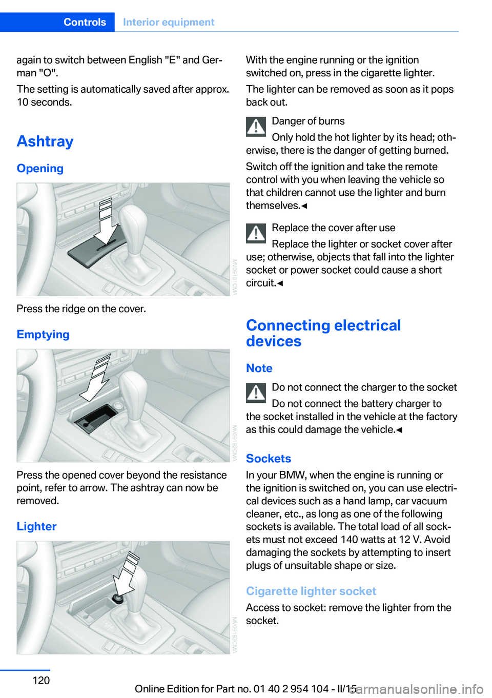
Ashtray
Opening
Press the ridge on the cover.
Emptying
Press the opened cover beyond the resistance
point, refer to arrow. The ashtray can now be
removed.
Lighter
With the engine running or the ignition
switched on, press in the cigarette lighter.
The lighter can be removed as soon as it pops
back out.
Danger of burns
Only hold the hot lighter by its head; oth‐
erwise, there is the danger of getting burned.
Switch off the ignition and take the remote
control with you when leaving the vehicle so
that children cannot use the lighter and burn
themselves.◀
Replace the cover after use
Replace the lighter or socket cover after
use; otherwise, objects that fall into the lighter
socket or power socket could cause a short
circuit.◀
Connecting electrical
devices
Note Do not connect the charger to the socket
Do not connect the battery charger to
the socket installed in the vehicle at the factory
as this could damage the vehicle.◀
Sockets
In your BMW, when the engine is running or
the ignition is switched on, you can use electri‐
cal devices such as a hand lamp, car vacuum
cleaner, etc., as long as one of the following
sockets is available. The total load of all sock‐
ets must not exceed 140 watts at 12 V. Avoid
damaging the sockets by attempting to insert
plugs of unsuitable shape or size.
Cigarette lighter socket Access to socket: remove the lighter from the
socket.Seite 120ControlsInterior equipment120
Online Edition for Part no. 01 40 2 954 104 - II/15
Page 123 of 289
Under the center armrest
External audio device, refer to page 125.
In the passenger footwell A socket is located on the left below the glove
compartment.
Cargo area
Depending on your vehicle's equipment, the
following storage spaces can be found in the
cargo area:▷Rubber band for securing light objects.▷Storage compartment.
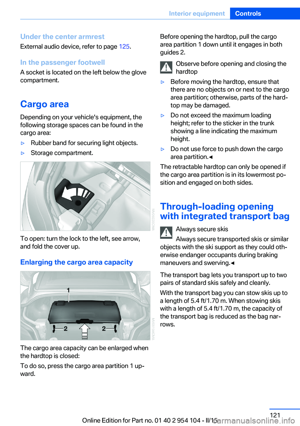
To open: turn the lock to the left, see arrow,
and fold the cover up.
Enlarging the cargo area capacity
The cargo area capacity can be enlarged when
the hardtop is closed:
To do so, press the cargo area partition 1 up‐
ward.
Before opening the hardtop, pull the cargo
area partition 1 down until it engages in both
guides 2.
Observe before opening and closing the
hardtop▷Before moving the hardtop, ensure that
there are no objects on or next to the cargo
area partition; otherwise, parts of the hard‐
top may be damaged.▷Do not exceed the maximum loading
height; refer to the sticker in the trunk
showing a line indicating the maximum
height.▷Do not use force to push down the cargo
area partition.◀
The retractable hardtop can only be opened if
the cargo area partition is in its lowermost po‐
sition and engaged on both sides.
Through-loading opening
with integrated transport bag
Always secure skis
Always secure transported skis or similar
objects with the ski support as they could oth‐
erwise endanger occupants during braking
maneuvers and swerving.◀
The transport bag lets you transport up to two
pairs of standard skis safely and cleanly.
With the transport bag you can stow skis up to a length of 5.4 ft/1.70 m. When stowing skis
with a length of 5.4 ft/1.70 m, the capacity of
the transport bag is reduced as the bag nar‐
rows.
Seite 121Interior equipmentControls121
Online Edition for Part no. 01 40 2 954 104 - II/15