2015 AUDI TT ROADSTER length
[x] Cancel search: lengthPage 25 of 244
Trip computer
Introduction
The trip computer gives you information on
current and average fuel mileage, average
speed, fuel range and driving time .
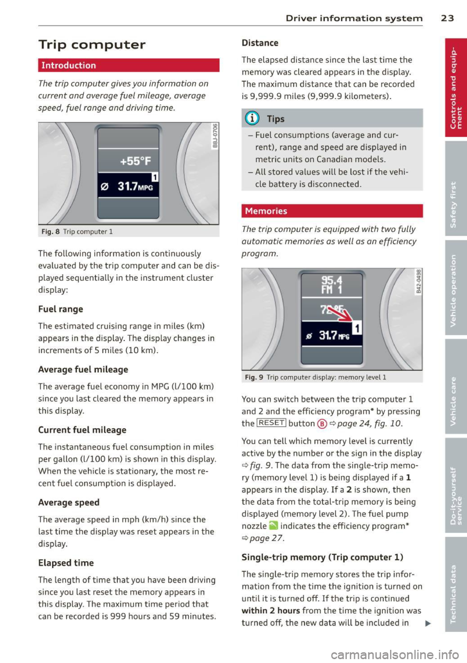
Fig. 8 T rip comp ute r 1
The fo llow ing informa tion is cont inuo usly
eva luated by the trip compu ter and can be dis
p layed sequentia lly in the instrument cl uster
d isplay:
Fuel range
The estimated c ruising ra nge in miles (km)
appears in the d isplay . The disp lay changes in
increments of 5 miles (10 km) .
Average fuel mileage
The average fue l economy in MPG (l/ 100 km)
since you last clea red the memory appears in
t his display .
Current fuel mileage
The instantaneous fuel consumption in miles
pe r gallon (l/ 100 km) is shown in this d isp lay .
When the ve hicle is stationary, the most re
cent fuel consumpt io n is displayed.
Average speed
The average speed in mph (km/h) since the
last time the display was reset appears i n the
d isp lay.
Elap sed t ime
The length of time that you have been driving
since you las t reset the memory appears in
this display . The maximum t ime period that
can be recorded is 999 ho urs and 59 minutes .
Driver in formation system 23
Distance
The elapsed dis tance sin ce the las t time the
memory was cleared appears in the d isp lay .
T he maxim um distance that can be recorded
is 9 ,999.9 miles (9,999 .9 k ilometers) .
(D Tips
- Fuel consump tions (average and cur
rent), range and speed are disp layed in
metric un its on Canadian mode ls.
- All sto red val ues wil l be lost if t he vehi
cle battery is d isconnected .
' . Memories
The trip computer is equipped with two fully
automatic memories as well as on efficiency
progrom.
Fi g. 9 Trip co mputer d isplay: memo ry level 1
You can switch between the trip computer 1
and 2 and the efficiency program* by pressing
the
I R ES ET I button @ c::> page 24, fig . 10 .
You can tell wh ich memory leve l is currently
active by the number or the sign in the display
c::> fig . 9. The data from the single-trip memo
ry (memo ry level 1) is being displayed if a
1
appea rs i n t he display . If a 2 is shown, then
the data from the total- trip memory is being
displayed (memory level 2). The f ue l pump
nozzle
ii indicates the efficiency program *
c::>poge 27.
Single-trip memory (Trip computer 1 )
The sing le -t rip memory stores the tr ip info r
ma tion from the time the ig nition is tu rned on
u nt il it is tur ned off. If the tr ip is cont inued
within 2 hour s from the time the ignit ion was
turned off, the new data will be included in ..,.
Page 51 of 244

light sensor checked as soon as possible at a
dealership.
Adaptive light *
The benefit of adaptive l ight is that the curve
and the edge of the road are better i llum inat
ed . The adaptive light is contro lled automati
cally, depending on vehicle speed and steering
wheel angle.
When driving a round bends, the head lights
are contro lled according to steering wheel an
g le . So that there is no black area ahead of the
ve hic le, the two main beams pivot at different
angles. The system works above a speed of
about 6 mph (10 km/h).
Com ing home /le avi ng home function *
The function is swit ched on when the switch is
in the AUTO* position and the function is
shown as active in the driver information sys
tem.
The
coming hom e function illuminates the
area around the vehicle when the ign ition is
switched off and the driver's door is ope ned.
The length of time the lights remain on can be
set in the menu display
( Illumination > Exte
rior lights > coming home ).
The leavi ng home function i lluminates the
area around the vehicle when unlocking it.
A WARNING
- Never use dayt ime running l ights to see
where you are going. They are not bright
enough and w ill not let you see far
enough ahead for safety, especially at
dusk or when it is dar k. Always switch on
the low beams at dusk or when i t is dar k.
- Automatic headlights a re only intended
to assist the dr iver. They do not re lieve
t he driver of his responsibi lity to check
t he headlights and to turn them on man
ually according to the current light and
visibility conditions. For example, fog
and rain cannot be detected by the light
sensors. So a lways switch on the head
lights under these weather cond itions
and when driving in the dark
jO .
Clear vis ion 49
- Crashes can happen when you cannot see
the road ahead and when you cannot be
seen by other motorists.
- Always turn on the headlights so that
youcanseeahe adandsothatothe ~
can see your car from the back .
- Please observe legal regulat ions w hen
using the ligh ting systems des cribed.
(D Tips
- T he light sensor for head light control is
located in the rear view mirror mount.
Do not apply any stickers to t he wind
shield in th is area to preven t malfunc
tions or fa ilures.
- Some exter io r l ighting funct ions can be
adjusted in t he driver i nformat ion sys
t em
~page 24.
- I f you remove the igni tion from t he igni
t ion lock while the headligh ts are s till
on, a buzzer wi ll sound as long as the
driver's door is o pen to remind yo u to
t u rn off the lights.
- Always observe the specific local regula
tions for your area as to when to use your
lights.
- With automatic headlights, the high
beam f unction is also available, but w ith
one restrict ion: If you have not sw itched
the high beams back to low beams dur
ing automatic headlight operation (for
example, after d riving throug h a tunnel),
only the low beams come on the next
t ime au tomati c headlights a re swi tched
on. To use the high beams , you firs t have
t o pull the hig h beam lever back and
then push the lever fo rward again .
- In coo l or damp weather, the inside of
the headlights, turn signals an d tail
lights can fog over due to the tempera
t u re difference between the inside and
outside. They w ill clear shortly after
switching them on. This does not affect
the se rv ice life of the lighting.
Page 59 of 244
Replacing windshield wiper blades
Wiper blades in good condition help keep the
windshield clear .
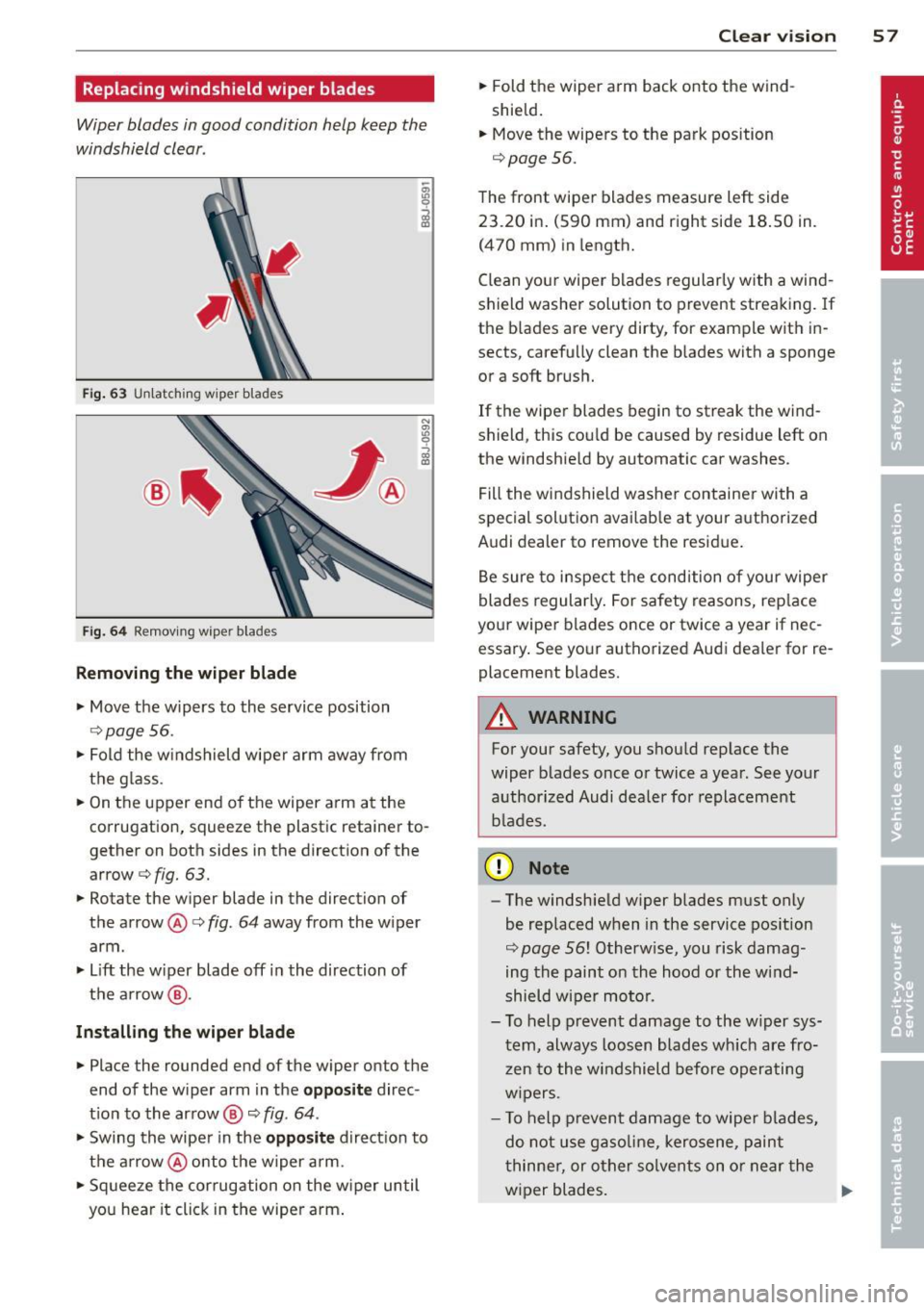
Fig. 63 U nl atc hing wiper bla des
Fi g. 6 4 Remov ing wipe r bla des
Removing the wip er blade
• Move the wipers to the service position
c::> page 56.
• Fold the w indshield wiper arm away from
the g lass.
• On the upper end of the wiper a rm at the
corrugation, squeeze the plastic retainer to
gether on both sides in the direction of the
arrow c::>
fig. 63.
• Rotate the w iper blade in the direction of
the arrow @c::>
fig. 64 away from the w iper
arm .
• Lift the w iper blade off in the direction of
the a rrow @.
Inst alling the wiper blade
• Place the rounded end of the wiper onto the
end of the wiper arm in the
opposit e direc
t ion to the arrow @ c::>
fig. 64 .
• Swing the wiper in the opposite direction to
the a rrow @onto the wiper arm.
• Sq ueeze the corrugation on the w iper until
you hear it click in the wipe r arm .
Clear vi sion 5 7
• Fold the wiper arm back onto the wind
shield.
• Move the wipers to the park position
c::>
page 56.
The front wipe r blades measure left side
23 .20 in . (590 mm) and right side 18 .50 in.
(470 mm) in length.
C lean you r wiper blades regularly with a wind
shield washer solution to prevent streaking. If
the b lades are very dirty, for examp le with in
sects, carefully clean the b lades with a sponge
or a soft brush.
If the wiper blades begin to streak the wind
shield, this cou ld be caused by residue left on
the windshie ld by automatic car washes.
Fill the wi ndshield washe r container with a
spec ial solutio n availab le at your aut horized
Audi dealer to remove the resid ue .
Be sure to inspect t he condition of your wiper
blades regularly. For safety reasons, rep lace
your wiper blades once or twice a year if nec
essary . See yo ur authorized Aud i dealer for re
placement blades.
A WARNING
For your safety, you shou ld rep lace the
wiper b lades once or twice a yea r. See your
a uthorized Audi dealer for replacement
b lades.
(D Note
- The w indshie ld w iper blades must only
be replaced w hen in the service pos ition
c::>
page 56! Otherw ise, you risk damag
ing the paint on the hood or the wind
shield wiper mo to r.
- T o help p revent damage to the w iper sys
tem, always loos en blades wh ich are fro
z en to the windshield before operating
w ipers.
- T o help p revent damage to wiper blades,
do not use gaso line, kero sene, paint
t hinne r, or other solvents on o r near the
w iper blades.
Page 60 of 244
58 Clear vision
-To help prevent damage to the wiper
arms or oth er components, do not at
tempt to move the wipers by hand.
@ Tips
- Commercial hot waxes applied by auto
matic car washes aff ect the cleanability
of the glass surface .
- The front wiper blades are different
lengths; the blade on the driver's side is
longer .
Digital compass
Activating or deactivating the compass
Applies to vehicles: with digital compass
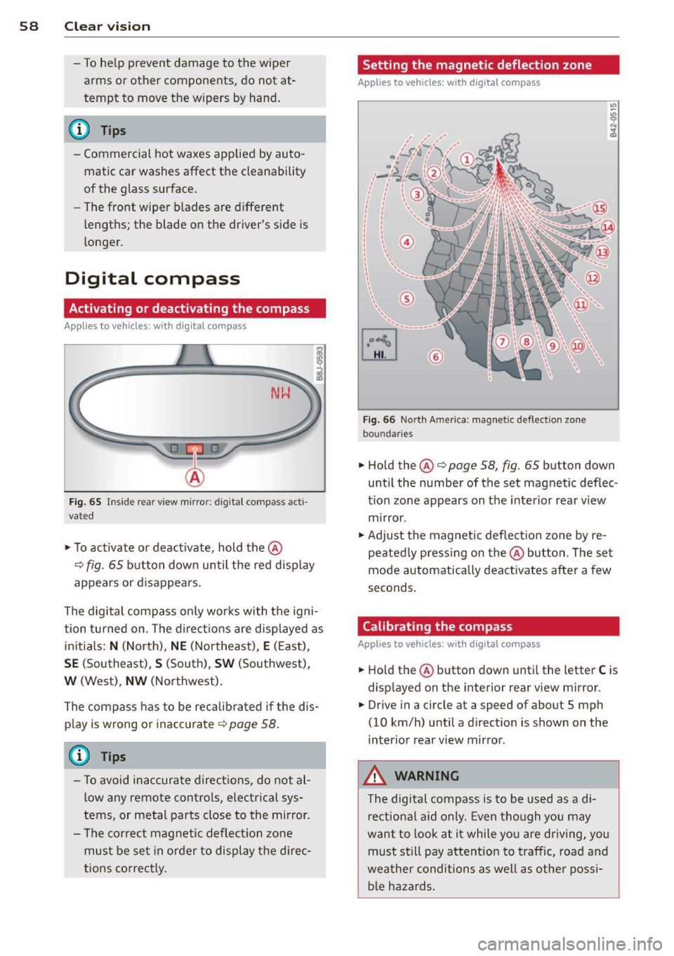
Fig. 65 Inside re ar view mirro r: di gital compass ac ti
va ted
• To activate or deactivate , hold the@
¢ fig. 65 button down until the red display
appears or disappears.
The digital compass only works with the igni
tion turned on . The directions are displayed as
initials:
N (North), NE (Northeast) , E (East),
SE (Southeast) , S (South), SW (Southwest),
W (West), NW (Northwest).
The compass has to be recalibrated if the dis
play is wrong or inaccurate
¢ page 58.
(j) Tips
-To avoid inaccurate directions, do not al
low any remote controls, electrical sys
tems, or metal parts close to the mirror.
- The correct magnetic deflection zone
must be set in order to display the direc
tions correctly.
Setting the magnetic deflection zone
Applies to vehicles: with digital compass
Fig. 66 North A meri ca : magn etic defle ction zo ne
bo undaries
• Hold the@¢ page 58, fig. 65 button down
until the number of the set magnetic deflec
tion zone appears on the interior rear view
mirror .
• Adjust the magnetic deflection zone by re
peatedly pressing on the@button. The set
mode automatically deactivates after a few
seconds.
Calibrating the compass
Applies to vehicles: with digital compass
• Hold the @button down until the letter C is
displayed on the interior rear view mirror .
• Drive in a circle at a speed of about S mph
(10 km/h) until a direction is shown on the
interior rear view mirror.
_&. WARNING
The digital compass is to be used as a di
rectional aid only. Even though you may
want to look at it while you are driving, you
must still pay attention to traffic, road and
weather conditions as well as other possi
ble hazards.
-
Page 65 of 244
.. Open the trunk lid.
.. Push the ski bag from the trunk through the
opening in the rear wall
c!;> _& .
.. Load up the ski bag.
Securing
.. Hook the sk i bag's safety strap @ ¢ fig. 71.
.. Adjust the reta ining strap @ to the desired
length.
.. Clip the retaining st rap .
Storage
.,. Unhook the ski bag's safety strap @
¢fig. 71.
.. Fold the cover ¢ fig. 70 downward in the op
posite direction of the arrow.
.. Loosen the reta ining strap @ .
.. Pull the ski bag backw ard through the rear
wall.
.. Close the cover of the pass -through to the
trunk .
.. Close the flip cover to the storage compart
ment between the seatbacks ¢
page 66.
.,. If necessary, collapse the ski bag.
& WARNING ,-
After loading, the ski bag must be secured
with the safety strap.
@ Tips
Make sure that the ski bag is not folded up
while still damp.
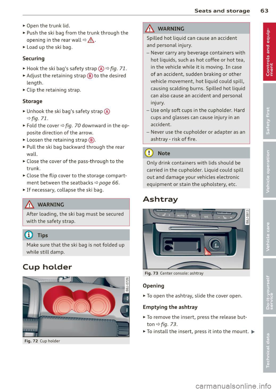
Cup holder
Fig. 72 Cup holder
Seats and storage 63
A WARNING
Spilled hot liquid can cause an accident
and personal injury .
- Never carry any beverage containers with
hot liquids, such as hot coffee or hot tea,
in the vehicle while it is moving. In case
of an acc ident, sudden braking or other
veh icle movement , hot liquid could spill,
causing scalding burns. Spilled hot liquid
can also cause an accident and personal
injury .
- Use only soft cups in the cupholder. Hard
cups and glasses can cause injury in an
accident .
- Never use the cupholder or adapter as an
ashtray - risk of fire .
(D Note
Only drink containers with lids should be
carried in the cupholder. Liquid could spill
out and damage you r vehicles electronic
equipment or stain the upholstery, etc.
Ashtray
Fig. 73 Center co n sole: ashtr ay
Opening
.. To open the ashtray, slide the cover open.
Emptying the ashtray
.. To remove the insert, press the release but
ton
c:> fig. 13 .
.. To install the insert, press it into the mount . .,.
Page 78 of 244
![AUDI TT ROADSTER 2015 Owners Manual 76 On the road
ignition, assum ing that you have not changed
or reset the setting.
The speed warning symbo l
ID] (USA models)/
1aj (Canada models) in the warning 1 displ ay
appears AUDI TT ROADSTER 2015 Owners Manual 76 On the road
ignition, assum ing that you have not changed
or reset the setting.
The speed warning symbo l
ID] (USA models)/
1aj (Canada models) in the warning 1 displ ay
appears](/manual-img/6/57664/w960_57664-77.png)
76 On the road
ignition, assum ing that you have not changed
or reset the setting.
The speed warning symbo l
ID] (USA models)/
1aj (Canada models) in the warning 1 displ ay
appears when you exceed the maximum
speed. It goes o ut when the speed fa lls below
the stored max imum speed .
The speed wa rning symbo l w ill also go out i f
the speed
exceeds the sto red max imum speed
by more than about 25 mph (40 km/h) for at
l east 10 seconds. The stored maxim um speed
is deleted .
Sett ing speed warning 1
¢page 76 .
Speed warning 2
Sto ring warning 2 is re commended if you al
ways
want to be reminded of a certa in speed,
for exam ple when yo u are traveling i n a cou n
try th at has a general maximum speed limi t,
or if you do not want to exceed a specified
speed for winter tires.
The speed w arning 2 symbol,
lDJ (USA mod
e ls)/
lDJ (Canada models) appea rs in the dis
p lay when you exceed the stored speed limit .
Unlike warning 1, it will not go out unti l th e
vehicle speed drops below the stored speed limit.
Setting s peed warn ing 2
¢ page 77 .
@ Tips
Even t hough your vehicle is equ ipped wi th
a speed w arni ng sys tem, yo u shou ld st ill
watch the s peedomete r to make sure you
are not driving faster than the speed lim it.
Speed warning 1: setting a speed limit
Warning threshold 1 is set by the button .
Fig. 8 3 Sectio n of instru ment clus ter: Set/C heck b ut
to n
Storing the max imum speed
.,. Dr ive at the desired ma ximum speed.
.,. Press the knob buttonc>fig .
83 unti l the
speed warn ing
symbo1 1m1 (U SA mode ls)/ 181
(Canada models) appears.
Resetting the maximum speed
.,. Dr ive the veh icle at a spee d of at least
3 mph ( 5 km/h)
.,. Press the knob for more than 2 seconds.
T he speed warning symbol
ID] (USA mode ls)/
k•j
cate that the maximum speed has been stored
s uccessfully .
The maxim um speed remains stored until it is
c h anged by pressing the button aga in b rief ly
or unt il it is deleted by a lengthy push on the
button.
Page 153 of 244
the exhaust system and this could cause
the catalytic converter to overheat.
- Do not turn off the ignition while the ve
hicle is moving .
- Do not continue to operate yo ur vehicle
under these conditions, as otherwise fuel
can reach the cata lytic converter. This
could result in overheating of the con
verter, requ iring its replacement.
- To assure efficient operation of the Emis
sion Control System:
- Have your veh icle ma inta ined properly
and in acco rdance with the service rec
ommendations in your Warranty
&
Ma intenan ce booklet.
- Lac k of proper maintenance as well as
improper use of the vehicle will impa ir
t he funct ion of the emission control
system and cou ld lead to damage.
@ For the sake of the environment
Even when the Emission Contro l System is
operating p roperly, the exhaust gas can
have a s ulfu r- like exhaust gas smell under
some operating states. This depends on
the s ulfur content of the fue l being used.
Using a different brand of fuel may help,
or filling the tank w ith lead-free super
grade gasoline .
Shutting down vehicle
If you would like your veh icle to remain inop
erat ive for a longer period of time, contact an
Aud i or other specialized deale r. T hey can ad
vise you on necessary precautions e.g . corro
sion prevention, ma intenance and storage.
Pay attention to add itiona l information con
cerning the battery . Re fer to~
page 175.
Dri vin g and en vironm ent 151
Operate your vehicle
economically and
minimize pollution
General
Your personal style of driving will determine
the economy of your vehicle, as well as ex
haust and noise levels.
Fuel economy, environmenta l impact, and
wear on your eng ine, brakes and tires largely
depend on three factors:
- your personal d riving s tyle
- operati ng conditions
- technical limitat ions
If you ant ic ipate what you need to do next and
drive economically, you can easily cut you r
fuel consumpt io n by 1O-lS percent . T his sec
tion w ill give you some tips on how you can
help the env ironment and your po cketbook.
@ Tips
The consumption estimates as published
by ENVIRONME NTAL PROT ECTI ON AGENCY
( E PA) a nd Tra nsp o rt Canada may no t corre
spond to your actual consump tion on the
r oad, which will va ry depending upon vehi
cle load and speed, road and weather con
ditions, trip length, etc.
Drive smoothly and keep a lookout
ahead
Vehicles use the most fuel when they are ac
celerating.
Avoid unnecessary acce lerating and braking .
Vehicles use the most f ue l when they are ac
ce le rat ing. If you ant icipate what is going to
happen next, you will need to brake less and,
thus, acce lerate less . Let the vehicle coast
whenever possible - for examp le when you see
that the next traff ic light is red.
•
•
Page 199 of 244
snow c hains are suitably cove red . Check
the position of the snow chains after
driving a few yards and correct if neces
sary. Follow the instructions from the
snow cha in manufacturer when doing so.
Where snow cha ins are mandatory oncer
tain roads, this normally also applies to
veh icles with all-wheel dr ive.
Wheel bolts
Wheel bolts must always be tightened to the
correct torque.
The design of whee l bolts is matched to the
factory insta lled r ims . If different rims are fit
ted, the correct wheel bo lts with the right
length and correctly shaped bolt heads must
be used. This ensures t hat wheels are fitted
securely and that the brake system functions
correctly .
In certain circumstances, you may not use
wheel bo lts from a different vehicle -even if it
i s the same model
¢ page 227.
A WARNING
Imprope rly tig htened or maintained wh eel
bolts can become loose ca using loss of
con trol, a collision and serious person al in
jury.
- Always keep the w heel bolts and the
threads in the wheel hubs clea n so the
wheel bolts can tu rn easily and be p rop
er ly tightened .
- Never grease or oil the wheel bo lts and
the threads in the wheel hubs. They can become loose w hile driving if greased or
o iled, even if tig htened to the specif ied
torque.
- Only use whee l bolts that belong to the
rim being installed.
- Never use different whee ls bolts on your
vehicle.
- Always maintai n the co rrect tig htening
torq ue fo r the wheel bo lts to reduce the
risk of a wheel loss. If the tightening tor-
Tire s an d wheel s 197
que of t he whee l bolts is too low, they
can loosen and come out when the vehi
cle is mov ing. If the tig htening torq ue is
too high, the wheel bolts and threads
can be damaged and the whee l can be
come loose.
(D Note
The specified torque for the whee l bolts is
90 ft lb (120 Nm) with a tolerance of± 7,4
ft lb(± 10 Nm). Torq ue whee l bolts diago
nally. After changing a whee l, the tor que
must be checked as soon as possible with a
torq ue w rench -prefe rably by an au thor
iz ed A udi de aler or qu alified workshop .
Low aspect ratio tires
Your Audi is factory -eq uipped w ith low aspect
r atio tires . These tires have been tho roughly
tested and been se lected specifically for your
model for their superb performance, road fee l
and handli ng under a var iety of driving condi
tions . Ask your authorized Audi dealer for
more d etails.
The low aspect ratio of these t ires is ind icated
by a numeral of
55 or less in the tire's s ize
designation . The numeral represents the ratio
of the t ire's sidewa ll height in relation to its
t read width exp ressed in pe rce ntage. Conven
t iona l tires have a he ight/w idth rat io of 60 or
more.
The performanc e of low-a spect-ratio tire s is
particularly sensitive to impr oper inflation
pre ssure .
It is therefore important that low
a spect ratio tire s are inflated to the specified
pres sure and that the inflation pressure is
regularly checked and maintained. Tire pre s
sures should be checked at least once a month and always befo re a long trip
¢ page 186, Checking tire pressure.
What you can do to avoid tire and rim
damage
Low aspect ratio tires can be damaged mo re
easily by impact w it h potholes, curbs, gul lies ..,.
•
•