Page 25 of 114

INSTRUMENT AND CONTROL FUNCTIONS
3-10
3
To display the stopwatch
To change the display to the stop-
watch mode, push the “SELECT” but-
ton and “RESET” button together. To
change the display back to the clock
mode, push the “SELECT” button and
“RESET” button together; however,
this is not possible when the stop-
watch is counting.
Standard measurement1. Push the “RESET” button to start
the stopwatch.
2. Push the “SELECT” button to stop the stopwatch.
3. Push the “SELECT” button again to reset the stopwatch.
Split time measurement1. Push the “RESET” button to start the stopwatch.
2. Push the start switch “ ” or “RE- SET” button to measure split
times. Split times are displayed on
the odometer display for five sec-
onds. 3. Push the start switch “ ” or “RE-
SET” button to display the final
split time or push the “SELECT”
button to stop the stopwatch and
display the final split time.
Split time history
The split time history displays up to 20
stored split times. The split time history
can be displayed either in reverse
chronological order or by speed. 1. Push the “SELECT” button for at least one second to select the re-
verse chronological order mode;
“L-20” displays on the stopwatch. Push the “SELECT” button again
to select the speed mode; “F-20”
displays on the stopwatch.
TIP
Reverse chronological order
mode: The split times are shown
from the latest to earliest (i.e., L1,
L2, L3, L4).
Speed order mode: The split times
are shown from the fastest to
slowest (i.e., F1, F2, F3, F4).2. Push the “RESET” button. De-
pending on the selected split time,
“L1” or “F1” displays on the cool-
ant temperature display/air intake
temperature display, and its corre-
sponding stored split time dis-
plays on the stopwatch.
3. Push the “SELECT” button to switch the displayed split time in
ascending order (i.e., 1, 2, 3, 4),
and the “RESET” button to switch
the displayed split time in de-
scending order (i.e., 20, 19, 18,
17).
1. Coolant temperature display/air intake tem-perature display
2. Stopwatch
21
U2SGE0E0.book Page 10 Wednesday, June 12, 2013 1:15 PM
Page 26 of 114

INSTRUMENT AND CONTROL FUNCTIONS
3-11
3
TIPTo switch between the reverse
chronological order mode and the
speed mode, push the “SELECT”
button for at least one second to
cancel the currently selected
mode, and then repeat step 1 to
select the desired mode.
To reset all the recorded times for
the selected split time history,
push the “RESET” button for at
least one second.4. Push the “SELECT” button for at
least one second to cancel the
split time history and return to the
time measurement. O
dometer, tripmeter, instantaneous
fuel consumption an d averag e fuel
consumption mo des
Push the “SELECT” button to switch
the display between the odometer
mode “ODO”, the tripmeter modes
“TRIP 1” and “TRIP 2”, the instanta-
neous fuel consumption mode “km/L”
or “L/100 km”, and the average fuel
consumption mode “AVE_ _._ km/L” or
“AVE_ _._ L/100 km” in the following
order:
ODO → TRIP 1 → TRIP 2 → km/L or
L/100 km → AVE_ _._ km/L or AVE_ _._
L/100 km → ODO For the UK only:
Push the “SELECT” button to switch
the display between the odometer
mode “ODO”, the tripmeter modes
“TRIP 1” and “TRIP 2”, the instanta-
neous fuel consumption mode “km/L”,
“L/100 km” or “MPG”, and the average
fuel consumption mode “AVE_ _._
km/L”, “AVE_ _._ L/100 km” or “AVE_
_._ MPG” in the following order:
ODO
→ TRIP 1 → TRIP 2 → km/L,
L/100 km or MPG → AVE_ _._ km/L,
AVE_ _._ L/100 km or AVE_ _._ MPG →
ODO
If the fuel level warning light comes on
(see page 3-4), the display automati-
cally changes to the fuel reserve trip-
meter mode “TRIP F” and starts
counting the distance traveled from
that point. In that case, push the “SE-
LECT” button to switch the display be-
tween the various tripmeter, odometer,
instantaneous fuel consumption and
average fuel consumption modes in
the following order:
1. Odometer/tripmeter/fuel reserve tripme- ter/instantaneous fuel consumption dis-
play/average fuel consumption display
1
U2SGE0E0.book Page 11 Wednesday, June 12, 2013 1:15 PM
Page 27 of 114

INSTRUMENT AND CONTROL FUNCTIONS
3-12
3
TRIP F
→ km/L or L/100 km → AVE_
_._ km/L or AVE_ _._ L/100 km → ODO
→ TRIP 1 → TRIP 2 → TRIP F
For the UK only:
TRIP F → km/L, L/100 km or MPG →
AVE_ _._ km/L, AVE_ _._ L/100 km or
AVE_ _._ MPG → ODO → TRIP 1 →
TRIP 2 → TRIP F
To reset a tripmeter, select it by push-
ing the “SELECT” button, and then
push the “RESET” button for at least
one second.
If you do not reset the fuel reserve trip-
meter manually, it resets itself auto-
matically and the display returns to the
prior mode after refueling and traveling
5 km (3 mi). Instantaneous fuel consumption mode
The instantaneous fuel consumption
display can be set to either “km/L”,
“L/100 km” or “MPG” (for the UK only).
“km/L”: The distance that can be
traveled on 1.0 L of fuel under the
current riding conditions is shown.
“L/100 km”: The amount of fuel
necessary to travel 100 km under
the current riding conditions is
shown.
“MPG” (for the UK only): The dis-
tance that can be traveled on
1.0 Imp.gal of fuel under the cur-
rent riding conditions is shown. To switch between the instantaneous
fuel consumption displays, push the
“SELECT” button for one second when
one of the displays is shown.
TIPIf traveling at speeds under 10 km/h
(6.0 mi/h), “_ _._” is displayed.Average fuel consumption modeThe average fuel consumption display
can be set to either “AVE_ _._ km/L”,
“AVE_ _._ L/100 km” or “AVE_ _._
MPG” (for the UK only).
This display shows the average fuel
consumption since it was last reset.
1. Instantaneous fuel consumption display
1
1. Average fuel consumption display
1
U2SGE0E0.book Page 12 Wednesday, June 12, 2013 1:15 PM
Page 28 of 114

INSTRUMENT AND CONTROL FUNCTIONS
3-13
3
“AVE_ _._ km/L”: The average dis-
tance that can be traveled on 1.0 L
of fuel is shown.
“AVE_ _._ L/100 km”: The average
amount of fuel necessary to travel
100 km is shown.
“AVE_ _._ MPG” (for the UK only):
The average distance that can be
traveled on 1.0 Imp.gal of fuel is
shown.
To switch between the average fuel
consumption displays, push the “SE-
LECT” button for one second when
one of the displays is shown.
To reset the average fuel consumption
display, select it by pushing the “SE-
LECT” button, and then push the “RE-
SET” button for at least one second.
TIPAfter resetting an average fuel con-
sumption display, “_ _._” is shown for
that display until the vehicle has trav-
eled 1 km (0.6 mi).
Transmission gear display
This display shows the selected gear.
The neutral position is indicated by “ ”
and by the neutral indicator light.
Drive mo de display This display indicates which drive
mode has been selected: “STD”, “A” or
“B”. For more details on the modes
and on how to select them, refer to
pages 3-18 and 3-20.
Coolant temperature
display
The coolant temperature display indi-
cates the temperature of the coolant.
TIPWhen the coolant temperature display
is selected, “C” is displayed for one
second, and then the coolant tempera-
ture is displayed.
1. Neutral indicator light “ ”
2. Transmission gear display
1. Drive mode display
211
1. Coolant temperature display
1
U2SGE0E0.book Page 13 Wednesday, June 12, 2013 1:15 PM
Page 29 of 114

INSTRUMENT AND CONTROL FUNCTIONS
3-14
3
NOTICE
ECA10022
Do not continue to operate the en-
gine if it is overheatin g.Air intake temperature display
The air intake temperature display indi-
cates the temperature of the air drawn
into the air filter case. Turn the key to
“ON”, and push the “RESET” button to
switch the coolant temperature display
to the air intake temperature display.
Push the “RESET” button again to re-
turn to the coolant temperature dis-
play.
TIP Even if the air intake temperature
is set to be displayed, the coolant
temperature warning light comes
on if the engine overheats.
When the key is turned to “ON”,
the coolant temperature is auto-
matically displayed, even if the air
intake temperature was displayed
prior to turning the key to “OFF”.
When the air intake temperature
display is selected, “A” is dis-
played for one second, and then
“A” and the air intake temperature
are displayed.
Traction control system mo de dis-
play
This display indicates which traction
control system mode has been select-
ed. For more details on the modes and
on how to select them, refer to page
3-22.
1. Air intake temperature display
1
1. Traction control system mode display
1
U2SGE0E0.book Page 14 Wednesday, June 12, 2013 1:15 PM
Page 30 of 114

INSTRUMENT AND CONTROL FUNCTIONS
3-15
3Self-d
iagnosis device
This model is equipped with a self-di-
agnosis device for various electrical
circuits.
If a problem is detected in the immobi-
lizer system circuits, the immobilizer
system indicator light flashes and the
display indicates an error code.
If a problem is detected in any other
circuit, the engine trouble warning light
comes on and the display indicates an
error code.
If the display indicates any error codes,
note the code number, and then have
a Yamaha dealer check the vehicle.
TIPIf the display indicates immobilizer sys-
tem circuit error code 52, this could be
caused by transponder interference. If
this error code appears, try following
the procedure below.1. Use the code re-registering key to start the engine.TIPMake sure there are no other immobi-
lizer keys close to the main switch, and
do not keep more than one immobilizer
key on the same key ring! Immobilizer
system keys may cause signal interfer-
ence, which may prevent the engine
from starting.2. If the engine starts, turn it off andtry starting the engine with the
standard keys.
3. If one or both of the standard keys do not start the engine, take the
vehicle, the code re-registering
key and both standard keys to a
Yamaha dealer and have the stan-
dard keys re-registered.
NOTICE
ECA11591
If the display in dicates an error
co de, the vehicle shoul d b e checked
as soon as possi ble in or der to avoi d
en gine damag e.Display bri ghtness an d shift timin g
in dicator li ght control mo de
This mode allows you to make chang-
es to five settings by performing the
following steps. 1. Turn the key to “OFF”.
2. Push and hold the “SELECT” but- ton.
1. Error code display
2. Immobilizer system indicator light
3. Engine trouble warning light “ ”
132
1. Shift timing indicator light activation range
2. Shift timing indicator light
3. Brightness adjustable displays
4. Brightness level display
1
2
3
4
U2SGE0E0.book Page 15 Wednesday, June 12, 2013 1:15 PM
Page 31 of 114

INSTRUMENT AND CONTROL FUNCTIONS
3-16
3
3. Turn the key to “ON”, and then re-
lease the “SELECT” button after
five seconds. The display bright-
ness function is selected.
4. Push the “SELECT” button to switch the functions in the order
below.a. Display brightness: This function allows you to ad-
just the brightness of the dis-
plays and tachometer to suit
the outside lighting conditions.
b. Shift timing indicator light ac- tivity:
This function allows you to
choose whether or not the indi-
cator light should be activated
and whether it should flash or
stay on when activated.
c. Shift timing indicator light acti- vation:
This function allows you to se-
lect the engine speed at which
the indicator light is activated.
d. Shift timing indicator light de- activation: This function allows you to se-
lect the engine speed at which
the indicator light is deactivat-
ed.
e. Shift timing indicator light brightness:
This function allows you to ad-
just the brightness of the indi-
cator light to suit your
preference.
TIPThe display shows the current setting
for each function, except the shift tim-
ing indicator light activity function.To adjust the brightness of the multi-function meter displays and tachome-ter1. Turn the key to “OFF”.
2. Push and hold the “SELECT” but- ton.
3. Turn the key to “ON”, and then re- lease the “SELECT” button after
five seconds.
4. Push the “RESET” button to select the desired brightness level. 5. Push the “SELECT” button to con-
firm the selected brightness level.
The control mode changes to the
shift timing indicator light activity
function.
To set the shift timing indicator light ac-
tivity function1. Push the “RESET” button to select one of the following indicator light
activity settings: The indicator light stays on
when activated. (This setting
is selected when the indicator
light stays on.)
The indicator light flashes
when activated. (This setting
is selected when the indicator
light flashes four times per
second.)
The indicator light is deacti-
vated; in other words, it does
not come on or flash. (This
setting is selected when the
indicator light flashes once
every two seconds.)
U2SGE0E0.book Page 16 Wednesday, June 12, 2013 1:15 PM
Page 32 of 114

INSTRUMENT AND CONTROL FUNCTIONS
3-17
32. Push the “SELECT” button to con-
firm the selected indicator light ac-
tivity. The control mode changes
to the shift timing indicator light
activation function.
To set the shift timing indicator light ac-
tivation functionTIPThe shift timing indicator light activa-
tion function can be set between 7000
r/min and 15000 r/min. From 7000
r/min to 12000 r/min, the indicator light
can be set in increments of 500 r/min.
From 12000 r/min to 15000 r/min, the
indicator light can be set in increments
of 200 r/min.1. Push the “RESET” button to select the desired engine speed for acti-
vating the indicator light.
2. Push the “SELECT” button to con- firm the selected engine speed.
The control mode changes to the
shift timing indicator light deacti-
vation function. To set the shift timing indicator light
deactivation functionTIP
The shift timing indicator light de-
activation function can be set be-
tween 7000 r/min and 15000
r/min. From 7000 r/min to 12000
r/min, the indicator light can be set
in increments of 500 r/min. From
12000 r/min to 15000 r/min, the in-
dicator light can be set in incre-
ments of 200 r/min.
Be sure to set the deactivation
function to a higher engine speed
than for the activation function,
otherwise the shift timing indicator
light remains deactivated.1. Push the “RESET” button to select
the desired engine speed for de-
activating the indicator light.
2. Push the “SELECT” button to con- firm the selected engine speed.
The control mode changes to the
shift timing indicator light bright-
ness function. To adjust the shift timing indicator light
brightness1. Push the “RESET” button to select
the desired indicator light bright-
ness level.
2. Push the “SELECT” button to con- firm the selected indicator light
brightness level. The display re-
turns to the odometer or tripmeter
mode.
U2SGE0E0.book Page 17 Wednesday, June 12, 2013 1:15 PM
 1
1 2
2 3
3 4
4 5
5 6
6 7
7 8
8 9
9 10
10 11
11 12
12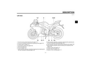 13
13 14
14 15
15 16
16 17
17 18
18 19
19 20
20 21
21 22
22 23
23 24
24 25
25 26
26 27
27 28
28 29
29 30
30 31
31 32
32 33
33 34
34 35
35 36
36 37
37 38
38 39
39 40
40 41
41 42
42 43
43 44
44 45
45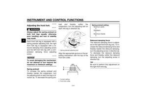 46
46 47
47 48
48 49
49 50
50 51
51 52
52 53
53 54
54 55
55 56
56 57
57 58
58 59
59 60
60 61
61 62
62 63
63 64
64 65
65 66
66 67
67 68
68 69
69 70
70 71
71 72
72 73
73 74
74 75
75 76
76 77
77 78
78 79
79 80
80 81
81 82
82 83
83 84
84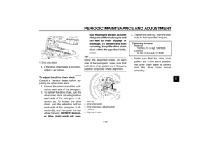 85
85 86
86 87
87 88
88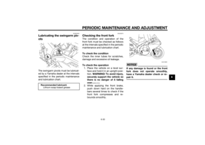 89
89 90
90 91
91 92
92 93
93 94
94 95
95 96
96 97
97 98
98 99
99 100
100 101
101 102
102 103
103 104
104 105
105 106
106 107
107 108
108 109
109 110
110 111
111 112
112 113
113