Page 25 of 92

INSTRUMENT AND CONTROL FUNCTIONS
3-10
3
Ri
ght
EAU12351
Pass switch “ ”
Press this switch to flash the headlight.
EAU12401
Dimmer switch “ / ”
Set this switch to “ ” for the high
beam and to “ ” for the low beam.
EAU12461
Turn si gnal switch “ / ”
To signal a right-hand turn, push this
switch to “ ”. To signal a left-hand
turn, push this switch to “ ”. When
released, the switch returns to the cen- ter position. To cancel the turn signal
lights, push the switch in after it has re-
turned to the center position.
EAU12501
Horn switch “ ”
Press this switch to sound the horn.
EAU12661
En
gine stop switch “ / ”
Set this switch to “ ” before starting
the engine. Set this switch to “ ” to
stop the engine in case of an emergen-
cy, such as when the vehicle overturns
or when the throttle cable is stuck.
EAU12713
Start switch “ ”
Push this switch to crank the engine
with the starter. See page 5-1 for start-
ing instructions prior to starting the en-
gine.
EAU41701
The engine trouble warning light will
come on when the key is turned to
“ON” and the start switch is pushed,
but this does not indicate a malfunc-
tion.
EAU12734
Hazar d switch “ ”
With the key in the “ON” or “ ” posi-
tion, use this switch to turn on the haz-
ard lights (simultaneous flashing of all
turn signal lights).
The hazard lights are used in case of an
emergency or to warn other drivers
when your vehicle is stopped where it
might be a traffic hazard.NOTICE
ECA10062
Do not use the hazar d lig hts for an
exten ded len gth of time with the en-
g ine not runnin g, otherwise the bat-
tery may d ischarge.
EAU42525
“SELECT” switch “ / ”
This switch is used to perform selec-
tions in the odometer and tripmeters,
to set the clock and to set the bright-
ness control mode of the multi-func-
tion meter unit.
See “Multi-function meter unit” on
page 3-6 for detailed information.
1. Engine stop switch “ / ”
2. Hazard switch “ ”
3. “SELECT” switch “ / ”
4. “RESET” switch
5. Start switch “ ”
U1CSE1E0.book Page 10 Friday, September 13, 2013 9:33 AM
Page 26 of 92

INSTRUMENT AND CONTROL FUNCTIONS
3-11
3
EAU42536
“RESET” switch
This switch is used to reset the tripme-
ters, to set the clock and to set the
brightness control mode of the multi-
function meter unit.
See “Multi-function meter unit” on
page 3-6 for detailed information.
EAU12821
Clutch leverThe clutch lever is located at the left
handlebar grip. To disengage the
clutch, pull the lever toward the han-
dlebar grip. To engage the clutch, re-
lease the lever. The lever should be
pulled rapidly and released slowly for
smooth clutch operation.
The clutch lever is equipped with a
clutch switch, which is part of the igni-
tion circuit cut-off system. (See page
3-18.)
EAU12882
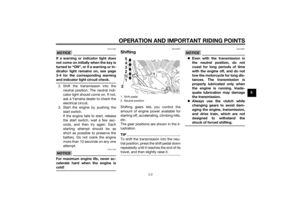
Shift pedalThe shift pedal is located on the left
side of the motorcycle and is used in
combination with the clutch lever when
shifting the gears of the 5-speed con-
stant-mesh transmission equipped on
this motorcycle.TIPUse your toes or heel to shift up and
your toes to shift down.
1. Clutch lever
1. Shift pedal
2. Neutral position
1
5432N1 5
4
3
2N1
2
U1CSE1E0.book Page 11 Friday, September 13, 2013 9:33 AM
Page 27 of 92

INSTRUMENT AND CONTROL FUNCTIONS
3-12
3
EAU12892
Brake leverThe brake lever is located on the right
side of the handlebar. To apply the
front brake, pull the lever toward the
throttle grip.
EAU58490
Brake pedalThe brake pedal is on the right side of
the vehicle.
To apply the rear brake, press down on
the brake pedal.
For UBS mo dels
When pressing down on the brake
pedal, the rear brake and a portion of
the front brake are applied. For full
braking performance, apply both the
brake lever and the brake pedal simul-
taneously.
EAU13075
Fuel tank capTo open the fuel tank cap
Open the fuel tank cap lock cover, in-
sert the key into the lock, and then turn
it 1/4 turn clockwise. The lock will be
released and the fuel tank cap can be
opened.
To close the fuel tank cap 1. Push the fuel tank cap into posi- tion with the key inserted in the
lock.
2. Turn the key counterclockwise to the original position, remove it,
and then close the lock cover.
1. Brake lever
1. Brake pedal
1. Fuel tank cap lock cover
2. Unlock.
2
1
U1CSE1E0.book Page 12 Friday, September 13, 2013 9:33 AM
Page 28 of 92

INSTRUMENT AND CONTROL FUNCTIONS
3-13
3
TIPThe fuel tank cap cannot be closed un-
less the key is in the lock. In addition,
the key cannot be removed if the cap is
not properly closed and locked.
WARNING
EWA11092
Make sure that the fuel tank cap is
properly closed after fillin g fuel.
Leakin g fuel is a fire hazar d.
EAU13222
FuelMake sure there is sufficient gasoline in
the tank.
WARNING
EWA10882
Gasoline an d g asoline vapors are
extremely flamma ble. To avoi d fires
an d explosions an d to re duce the
risk of injury when refuelin g, follow
these instructions.1. Before refueling, turn off the en- gine and be sure that no one is sit-
ting on the vehicle. Never refuel
while smoking, or while in the vi-
cinity of sparks, open flames, or
other sources of ignition such as
the pilot lights of water heaters
and clothes dryers.
2. Do not overfill the fuel tank. When refueling, be sure to insert the
pump nozzle into the fuel tank filler
hole. Stop filling when the fuel
reaches the bottom of the filler
tube. Because fuel expands when
it heats up, heat from the engine or
the sun can cause fuel to spill out
of the fuel tank. 3. Wipe up any spilled fuel immedi-
ately. NOTICE: Immediately
wipe off spille d fuel with a clean,
d ry, soft cloth, since fuel may
d eteriorate painted surfaces or
plastic parts.
[ECA10072]
4. Be sure to securely close the fuel tank cap.
WARNING
EWA15152
Gasoline is poisonous an d can cau-
se injury or death. Han dle gasoline
with care. Never siphon gasoline by
mouth. If you shoul d swallow some
g asoline or inhale a lot of gasoline
vapor, or g et some gasoline in your
eyes, see your d octor immediately. If1. Fuel tank filler tube
2. Maximum fuel level1
2
U1CSE1E0.book Page 13 Friday, September 13, 2013 9:33 AM
Page 29 of 92

INSTRUMENT AND CONTROL FUNCTIONS
3-14
3
g
asoline spills on your skin, wash
with soap an d water. If gasoline
spills on your clothin g, chan ge your
clothes.
EAU57690
NOTICE
ECA11401
Use only unlea ded g asoline. The use
of lead ed g asoline will cause severe
d amag e to internal en gine parts,
such as the valves an d piston rin gs,
as well as to the exhaust system.Your Yamaha engine has been de-
signed to use regular unleaded gaso-
line with a research octane number of
95 or higher. If knocking (or pinging)
occurs, use a gasoline of a different brand or premium unleaded fuel. Use
of unleaded fuel will extend spark plug
life and reduce maintenance costs.
Gasohol
There are two types of gasohol: gaso-
hol containing ethanol and that con-
taining methanol. Gasohol containing
ethanol can be used if the ethanol con-
tent does not exceed 10% (E10). Gas-
ohol containing methanol is not
recommended by Yamaha because it
can cause damage to the fuel system
or vehicle performance problems.
EAU51172
Fuel tank
breather hose an d
overflow hoseBefore operating the motorcycle:
Check each hose connection.
Check each hose for cracks or
damage, and replace if necessary.
Make sure that the end of each
hose is not blocked, and clean if
necessary.
Recommen ded fuel:
Regular unleaded gasoline (Gasohol
(E10) acceptable)
Fuel tank capacity:
19.0 L (5.02 US gal, 4.18 Imp.gal)
Fuel reserve amount (when the fuel
level warnin g li ght comes on):
3.7 L (0.98 US gal, 0.81 Imp.gal)
1. Fuel tank overflow hose
2. Fuel tank breather hose
21
U1CSE1E0.book Page 14 Friday, September 13, 2013 9:33 AM
Page 30 of 92

INSTRUMENT AND CONTROL FUNCTIONS
3-15
3
EAU13434
Catalytic converterThis model is equipped with a catalytic
converter in the exhaust system.
WARNING
EWA10863
The exhaust system is hot after op-
eration. To prevent a fire hazard or
b urns:
Do not park the vehicle near
possi ble fire hazard s such as
g rass or other materials that
easily burn.
Park the vehicle in a place
where ped estrians or chil dren
are not likely to touch the hot
exhaust system.
Make sure that the exhaust sys-
tem has cooled down before
d oin g any maintenance work.
Do not allow the en gine to i dle
more than a few minutes. Lon g
i d lin g can cause a b uild-up of
heat.
NOTICE
ECA10702
Use only unlea ded g asoline. The use
of lead ed g asoline will cause unre-
pairab le dama ge to the catalytic
converter.
EAU42753
Ri der seatTo remove the ri der seat
1. Insert the key into the seat lock, and then turn it counterclockwise.
2. Lift the front of the rider seat up, and then pull the rider seat off.
To install the ri der seat
1. Insert the projection on the rear of the rider seat into the seat holder
as shown.1. Seat lock
2. Unlock.
U1CSE1E0.book Page 15 Friday, September 13, 2013 9:33 AM
Page 31 of 92
INSTRUMENT AND CONTROL FUNCTIONS
3-16
3
2. Push the front of the seat down to lock it in place.
3. Remove the key.
TIPMake sure that the rider seat is proper-
ly secured before riding.
EAU14325
Helmet hol derThe helmet holder is located under the
rider seat.
To secure a helmet to the helmet
hol der
1. Remove the rider seat. (See the previous section “Rider seat”.)
2. Hook the helmet onto the helmet holder, and then securely install
the seat. WARNING! Never ri de
with a helmet attached to the
helmet hol der, since the helmet
may hit o bjects, causin g loss of
control an d possi bly an acci-
d ent.
[EWA10162]
To release the helmet from the hel-
met hol der
Remove the rider seat, remove the hel-
met from the helmet holder, and then
install the seat.
1. Projection
2. Seat holder
1
2
1. Helmet holder
1
U1CSE1E0.book Page 16 Friday, September 13, 2013 9:33 AM
Page 32 of 92

INSTRUMENT AND CONTROL FUNCTIONS
3-17
3
EAU42547
Adjustin g the shock a bsorb er
assem blyThis shock absorber assembly is
equipped with a spring preload adjust-
ing ring, allowing the spring preload to
be adjusted to suit the rider’s prefer-
ence.
It is recommended to have a Yamaha
dealer adjust the spring preload.
Should you choose to make the adjust-
ment, use the special wrench included
in the additional tool kit, which was
handed out separately at the purchase
of the vehicle.NOTICE
ECA10102
To avoi d d amag ing the mechanism,
d o not attempt to turn b eyond the
maximum or minimum setting s.Adjust the spring preload as follows.
To increase the spring preload and
thereby harden the suspension, turn
the adjusting ring in direction (a). To
decrease the spring preload and there-
by soften the suspension, turn the ad-
justing ring in direction (b).
TIPAlign the appropriate notch in the ad-
justing ring with the position indicator
on the shock absorber.
WARNING
EWA10222
This shock absor ber assem bly con-
tains hi ghly pressurize d nitro gen
g as. Rea d an d und erstan d the fol-
lowin g information b efore handlin g
the shock a bsor ber assem bly.
Do not tamper with or attempt
to open the cylin der assem bly.
Do not su bject the shock a b-
sor ber assem bly to an open
flame or other hi gh heat source.
This may cause the unit to ex-
plo de due to excessive gas
pressure.
Do not deform or d amage the
cylin der in any way. Cylin der
d amag e will result in poor
d ampin g performance.
Do not d ispose of a damag ed or
worn-out shock a bsor ber as-
sem bl
y yourself. Take the shock
a b sor ber assem bly to a Yamaha
d ealer for any service.
1. Shock absorber assembly
2. Position indicator
3. Spring preload adjusting ringSprin g preloa d setting :
Minimum (soft): 1
Standard: 4
Maximum (hard):
923
U1CSE1E0.book Page 17 Friday, September 13, 2013 9:33 AM