2014 SUBARU TRIBECA radio
[x] Cancel search: radioPage 104 of 426
or wiring of the SRS airbag system.
This includes following modifica-tions.
.Installation of custom steeringwheels
.Attachment of additional trimmaterials to the dashboard
.Installation of custom seats
.Replacement of seat fabric orleather
.Installation of additional fabric orleather on the front seat
.Attachment of a hands-free mi-crophone or any other accessoryto a front pillar, a center pillar, arear pillar, the windshield, a sidewindow, an assist grip, or anyother cabin surface that would benear a deploying SRS curtainairbag.
.Installation of additional electri-cal/electronic equipment such asa mobile two-way radio on ornear the SRS airbag systemcomponents and/or wiring is notadvisable. This could interferewith proper operation of theSRS airbag system.
CAUTION
Do not perform any of the followingmodifications. Such modificationscan interfere with proper operationof the SRS airbag system.
.Attachment of any equipment(bush bar, winches, snow plow,skid plate, etc.) other than genu-ine SUBARU accessory parts.
.Modificationof the suspensionsystem or front end structure.
.Installation of a tire of differentsize and construction from thetires specified on the vehicleplacardattached to the driver’sdoor pillar or specified for indivi-dual vehicle models in this Own-er’s Manual.
.Attachment of any equipment(side steps or side sill protectors,etc.) other than genuine SUBARUaccessory parts to the side body.
Always consult your SUBARU dealer ifyou want to install any accessory parts onyour vehicle.
Seat, seatbelt and SRS airbags1-73
Page 113 of 426
2-8Keys and doors
door locking switches.
&Key lock-in prevention func-
tion
This function prevents the doors frombeing locked with the key still in theignition switch.
!Behavior with key lock-in preven-tion function operational
.With either the driver’s or front passen-ger’s door open, the doors automaticallyremain unlockedeven if the“”side of thedoor locking switch is pushed.
.It is possible to lock the all doors andthe rear gate by holding the“”side of thedoor locking switch pushed for 3 secondswith the driver’sdooropenandthenclosing the driver’s door.
!Behavior with key lock-in preven-tion function non-operational
.If the lock lever is turned to the rear(“LOCK”) position with the driver’s dooropen and the driver’s door is then closedwith the lock lever in that position, thedriver’s door is locked.
.If the spare key is used to lock thedriver’sdoorfromtheoutsideofthevehicle, the door is locked.
This function’soperational/non-opera-
tional setting can be changed by aSUBARU dealer. Contact a SUBARUdealer for details.
NOTE
When leaving the vehicle, make sureyou are holding the key before lockingthe doors.
Remote keyless entry system
CAUTION
.Do not expose the remote trans-mitter to severe shocks, such asthose experienced as a result ofdroppingor throwing.
.Do not take the remote transmit-ter apart except when replacingthe battery.
.Do not get the remote transmitterwet. If it gets wet, wipe it dry witha cloth immediately.
.When you carry the remote trans-mitter on an airplane, do notpress the button of the remotetransmitter whilein the airplane.When any button of the remotetransmitter is pressed, radiowaves are sent and may affectthe operation of the airplane.When you carry the remote trans-mitter in a bag on an airplane,take measures to prevent thebuttons of the remote transmitterfrom being pressed.
This device complies with Part 15 ofthe FCC Rules and with RSS-210 ofIndustry Canada. Operation is subject
Page 114 of 426
to the following two conditions: (1) Thisdevice may not cause harmful inter-ference, and (2) this device mustaccept any interference received, in-cluding interference that may causeundesired operation.
Changes or modifications not ex-pressly approved by the party respon-sible for compliance could void theuser’s authority to operate the equip-ment.
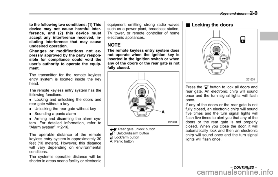
The transmitter for the remote keylessentry system is located inside the keyhead.
The remote keyless entry system has thefollowing functions.
.Locking and unlocking the doors andrear gatewithout a key
.Unlocking the rear gate without key
.Sounding a panic alarm
.Arming and disarming the alarm sys-tem. For detailed information, refer to“Alarm system”F2-16.
The operable distance of the remotekeyless entry system is approximately 30feet (10 meters). However, this distancewill vary depending on environmentalconditions.
The system’s operable distance will beshorter in areas near a facility or electronic
equipment emitting strong radio wavessuch as a power plant, broadcast station,TV tower, or remote controller of homeelectronic appliances.
NOTE
The remote keyless entry system doesnot operate when the ignition key isinserted in the ignition switch or whenany of the doors or the rear gate is notfully closed.
: Rear gate unlock button: Unlock/disarm button: Lock/arm buttonA: Panic button
&Locking the doors
Press the“”button to lock all doors andrear gate. An electronic chirp will soundonce and the turn signal lights will flashonce.
If any of the doors or the rear gate is notfully closed, an electronic chirp will soundfive times and the turn signal lights willflash five times to alert you that any of thedoorsor the rear gate is not properlyclosed. When you close the door, it willautomatically lock and then an electronicchirp will sound once and the turn signallights will flash once.
Keys and doors2-9
–CONTINUED–
Page 137 of 426
3-4Instruments and controls
&Acc
In this position the electrical accessories(radio, accessory power outlet, etc.) canbe used.
&ON
This is the normal operating position afterthe engine is started.
&START
CAUTION
Do not turn the ignition switch to the“START”position while the engineis running.
The engineis started in this position. Thestarter cranks the engine to start it. Whenthe key is released (after the engine hasstarted), the key automatically returns tothe“ON”position.
If your registered key fails to start theengine, pull out the key once (the securityindicator light will blink), and then insertthe key in the ignition switch and turn it tothe“START”position and again try to startthe engine.
NOTE
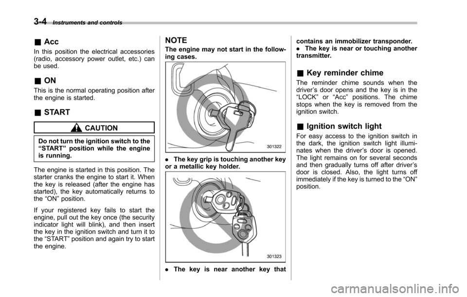
The engine may not start in the follow-ing cases.
.The key grip is touching another keyor a metallic key holder.
.Thekey is near another key that
contains an immobilizer transponder..The key is near or touching anothertransmitter.
&Key reminder chime
The reminder chime sounds when thedriver’s door opens and the key is in the“LOCK”or“Acc”positions. The chimestops when the key is removed from theignition switch.
&Ignition switch light
For easy access to the ignition switch inthe dark, the ignition switch light illumi-nates whenthe driver’s door is opened.The light remains on for several secondsand then gradually turns off after driver’sdoor is closed. Also, the light turns offimmediately if the key is turned to the“ON”position.
Page 192 of 426
Antenna system.................................................. 5-2Printed antenna................................................... 5-2FM reception....................................................... 5-2
Installation of accessories.................................. 5-2
Audio set............................................................. 5-3Type A audio set................................................. 5-3Type B audio set................................................. 5-3
Type A audio set (if equipped)........................... 5-4Radio operation................................................... 5-4Compact disc player operation........................... 5-10
Type B audio set (if equipped).......................... 5-15Radio operation................................................. 5-15Built in CD changer operation ............................ 5-21
Audio control buttons....................................... 5-26MODE button..................................................... 5-26
Auxiliary input jack............................................ 5-28
Rear Seat Entertainment (RSE) systemoperation (if equipped)................................... 5-29
Precautions to observe when handling acompact disc................................................... 5-29
Audio
5
Page 193 of 426

5-2Audio
Antenna system
&Printed antenna
CAUTION
Do not use sharp instruments orwindow cleaner containing abra-sives to clean the inner surface ofthewindow on which the antenna isprinted. Doing so may damage theantenna printed on the window.
The antenna is printed on the innersurface of the rear window glass.
NOTE
Antenna performance will deterioratesignificantly if you apply tinting film or
any other material over the antennaportion of the rear window glass.
&FM reception
Although FM is normally static free,reception can be affected by the surround-ing area, atmospheric conditions, stationstrength and transmitter distance. Build-ings or other obstructions may causemomentary static, flutter or station inter-ference. If reception continues to beunsatisfactory, switch to a stronger station.
NOTE
If a cell phone is placed near the radio,it may cause the radio to emit noisewhen it receives calls. This noise doesnot indicate a radio malfunction.
Installation of accessories
Always consult your SUBARU dealerbefore installing a citizen band radio orother transmitting device in your vehicle.Such devices may cause the electroniccontrol system to malfunction if they areincorrectly installed or if they are notsuited for the vehicle.
Page 194 of 426
Audio set
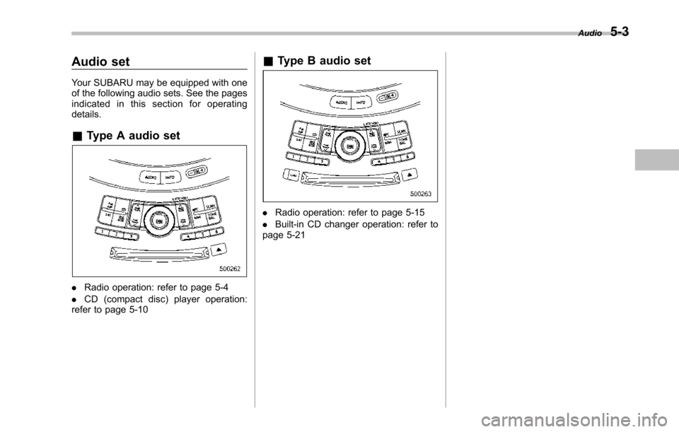
Your SUBARU may be equipped with oneof the following audio sets. See the pagesindicated in this section for operatingdetails.
&Type A audio set
.Radio operation: refer to page 5-4
.CD (compact disc) player operation:refer to page 5-10
&Type B audio set
.Radio operation: refer to page 5-15
.Built-in CD changer operation: refer topage 5-21
Audio5-3
Page 195 of 426
5-4Audio
Type A audio set (if equipped)
The audio set will operate only when the ignition switch is in the“Acc”or“ON”position.
&Radio operation
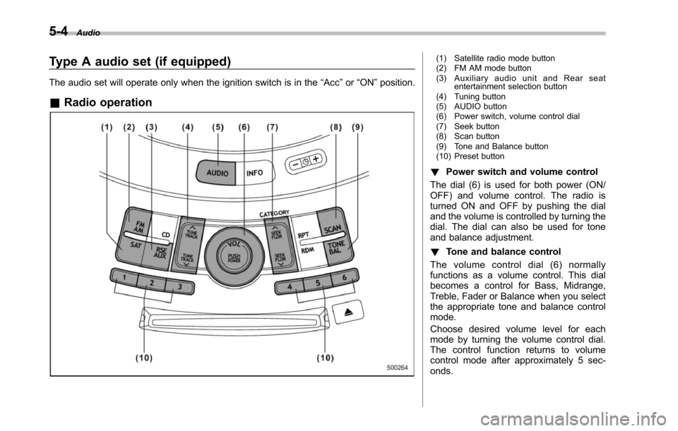
(1) Satellite radio mode button(2) FM AM mode button(3) Auxiliary audio unit and Rear seatentertainment selection button(4) Tuning button(5) AUDIO button(6) Power switch, volume control dial(7) Seek button(8) Scan button(9) Tone and Balance button(10) Preset button
!Power switch and volume control
The dial (6) is used for both power (ON/OFF) and volume control. The radio isturned ON and OFF by pushing the dialand the volume is controlled by turning thedial. The dial can also be used for toneand balance adjustment.
!Tone and balance control
The volume control dial (6) normallyfunctions as a volume control. This dialbecomes a control for Bass, Midrange,Treble, Fader or Balance when you selectthe appropriate tone and balance controlmode.
Choose desired volume level for eachmode by turning the volume control dial.The control function returns to volumecontrol mode after approximately 5 sec-onds.