2014 SUBARU TRIBECA engine
[x] Cancel search: enginePage 187 of 426
4-10Climate control
–Do not cover the sensors.
The sensors are located as follows.
–Solar sensor: beside windshielddefroster grille
–Interior air temperature sensor: on theside of the driver-side part of the centerpanel
–Outside temperature sensor: behindfront grille
Operating tips for heater and
air conditioner
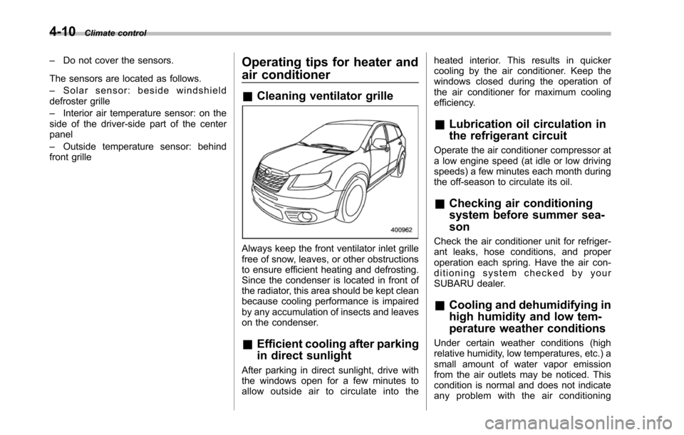
&Cleaning ventilator grille
Always keep the front ventilator inlet grillefree of snow, leaves, or other obstructionsto ensure efficient heating and defrosting.Since the condenser is located in front ofthe radiator, this area should be kept cleanbecause cooling performance is impairedby any accumulation of insects and leaveson the condenser.
&Efficient cooling after parking
in direct sunlight
After parking in direct sunlight, drive withthe windows open for a few minutes toallow outside air to circulate into the
heated interior. This results in quickercooling by the air conditioner. Keep thewindows closed during the operation ofthe air conditioner for maximum coolingefficiency.
&Lubrication oil circulation in
the refrigerant circuit
Operate the air conditioner compressor ata low engine speed (at idle or low drivingspeeds) a few minutes each month duringthe off-season to circulate its oil.
&Checking air conditioning
system before summer sea-
son
Check the air conditioner unit for refriger-ant leaks,hose conditions, and properoperation each spring. Have the air con-ditioning system checked by yourSUBARU dealer.
&Cooling and dehumidifying in
high humidity and low tem-
perature weather conditions
Under certain weather conditions (highrelative humidity, low temperatures, etc.) asmall amount of water vapor emissionfrom the air outlets may be noticed. Thiscondition is normal and does not indicateany problem with the air conditioning
Page 188 of 426
system.
&Air conditioner compressor
shut-off when engine is
heavily loaded
To improve acceleration and gas mileage,the air conditioner compressor is designedto temporarily shut off during air condi-tioner operation whenever the acceleratoris fully depressed such as during rapidacceleration or when driving on a steepupgrade.
&Refrigerant for your climate
control system
Your air conditioner uses ozone friendlyrefrigerant HFC134a. Therefore, the meth-od of adding, changing or checking therefrigerant is different from the method forCFC12 (freon). Consult your SUBARUdealer for service. Repairs needed as aresult of using the wrong refrigerant arenot covered under warranty.
Air filtration system
Replace the filter element according to thereplacement schedule shown in the fol-lowing. This schedule should be followedto maintain the filter’sdustcollectionability. Under extremely dusty conditions,the filter should be replaced more fre-quently. It is recommended that you haveyour filter checked or replaced by yourSUBARU dealer. For replacement, werecommend the use of a genuineSUBARU airfilter kit.
Replacement schedule:
Every 15 months or 15,000 miles (24,000km) whichever comes first
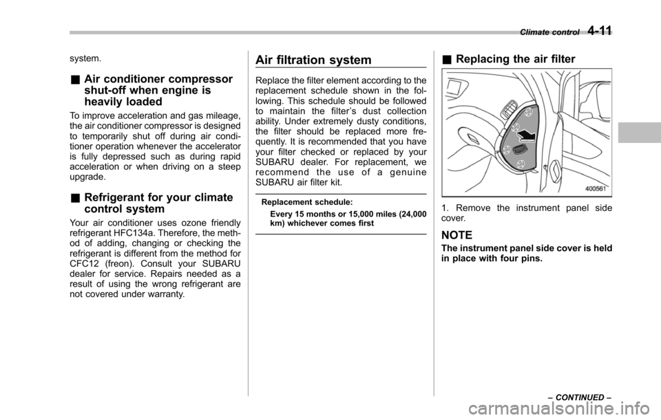
&Replacing the air filter
1. Remove the instrument panel sidecover.
NOTE
The instrument panel side cover is heldin place with four pins.
Climate control4-11
–CONTINUED–
Page 226 of 426
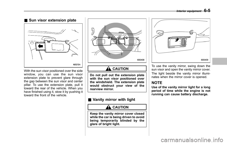
&Sun visor extension plate
With the sun visor positioned over the sidewindow, you can use the sun visorextension plate to prevent glare throughthe gap between the sun visor and centerpillar. To use the extension plate, pull ittoward the rear of the vehicle. When youhave finished using it, stow it by pushing ittoward the front of the vehicle.
CAUTION
Do not pull out the extension platewith the sun visor positioned overthe windshield. The extension platewould obstruct your view of therearview mirror.
&Vanity mirror with light
CAUTION
Keep the vanity mirror cover closedwhile the car is being driven to avoidbeing temporarily blinded by theglare of bright light.
To use the vanity mirror, swing down thesun visor and open the vanity mirror cover.
The light beside the vanity mirror illumi-nates when the mirror cover is opened.
NOTE
Use of the vanity mirror light for a longperiod of time while the engine is notrunning can cause battery discharge.
Interior equipment6-5
Page 232 of 426
especially metal ones such ascoins or aluminum foil, into theaccessory power outlet. Thatcould cause a short circuit. Al-ways put the cap on the acces-sory power outlet when it is notin use.
.Use only electrical applianceswhich are designed for 12V DC.
The maximum power rating of anappliance that can be connectedis shown in the following list. Donot usean appliance which ex-ceeds the indicated wattage foreach outlet.
–The two outlets in the centerconsole: 120W or less (Whenusing appliances connectedto two outlets simultaneously,the total power consumed bythem must not exceed 120W.)
–The two outlets in the rearcabin: 120W or less (Whenusing appliances connectedto two outlets simultaneously,the total power consumed bythem must not exceed 120W.)
Overloading the accessorypower outlet cancause a shortcircuit. Do not use dual adaptersor more than one electrical appli-
ance.
.If the plug on your electric appli-ance is either too loose or tootight for the accessory poweroutlet, this can result in a poorcontact or cause the plug to getstuck. Only use plugs that fitproperly.
.Use of an electric appliance in theaccessory power outlet for a longperiod of time while the engine isnot running can cause batterydischarge.
.Before driving your vehicle, makesure that the plug and the cordon your electrical appliance willnot interfere with your shiftinggears and operating the accel-erator and brake pedals. If theydo, do not use the electricalappliance while driving.
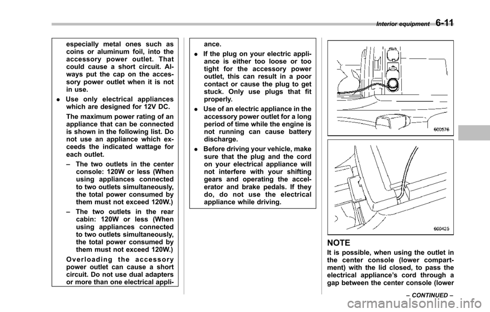
NOTE
It is possible, when using the outlet inthe center console (lower compart-ment) with the lid closed, to pass theelectrical appliance’s cord through agap between the center console (lower
Interior equipment6-11
–CONTINUED–
Page 243 of 426
6-22Interior equipment
the surrounding area with youreyes and mirrors, and movebackward at a slow speed. Mov-ing backward only by checkingthe rear view image from thecamera could cause an accident.
.Do not disassemble or modify thecamera, switch or wiring. Ifsmoke comes out or you smella strange odor, stop using therear view camera immediately.Contact your SUBARU dealerfor an inspection. Continued usemay result in accident, fire orelectric shock.
CAUTION
.If your vehicle is washed with ahigh-pressure washer, do notallow water to contact the cameradirectly. Entry of water in thecamera lens may result in con-densation, malfunction, fire orelectric shock.
.Since the camera is a precisiondevice, do not subject it to strongimpacts. Otherwise, malfunction,fire or electric shock may occur.
.If mud or snow sticks to or isfrozen on the camera, you must
be very careful removing it.Otherwise, damage done to thecamera may cause a fire orelectric shock. Pour water orlukewarm water over the camerato remove mud and ice, and wipeit with a soft, dry cloth.
.Do not put a flame close to thecamera or wiring. Otherwise, da-mage or fire may occur.
.When replacing the fuse, be sureto use a fuse with the specifiedrating. Use of a fuse with adifferent rating may result in amalfunction.
.If the rear view camera is used fora long time while the engine isnot operated, the battery maybecome completely discharged.
NOTE
.Do not wipe the camera with alcohol,benzine or paint thinner. Otherwise,discoloration may occur. To removecontamination, wipe the camera with acloth moistened with a diluted neutraldetergent and then wipe it with a soft,dry cloth..When waxing the vehicle, be carefulnot to apply the wax to the camera. If itcomes in contact with the camera,
moisten a clean cloth with a dilutedneutral detergent to remove the wax..The camera lens has hard coating tohelp prevent scratches. However, whenwashing the vehicle or cleaning thecamera lens, be careful not to scratchthe camera lens. Do not use a washingbrush directly on the camera lens. Themonitorscreen may be adversely af-fected..Strong light shined on the cameralens may develop white light stripesaround the light source. This is not amalfunction..Under the fluorescent light, the dis-play may flicker. However, this is not amalfunction..The image of the rear view cameramay be slightly different from theactual color of the objects.
&How to use the rear view
camera
When the select lever is set to“R”, the rearview camera automatically displays therear view image from the vehicle. Whenthe lever is set to other positions, theimage before setting to“R”is displayed.
1. Set the ignition switch to“ON”.
2. Set the select lever to“R”.
Page 248 of 426
Fuel...................................................................... 7-2Fuel requirements............................................... 7-2Fuel filler lid and cap........................................... 7-3
State emission testing (U.S. only)...................... 7-5
Preparing to drive............................................... 7-7
Starting the engine.............................................. 7-7
Stopping the engine............................................ 7-8
Remote engine start system (dealer option)..... 7-8Starting your vehicle........................................... 7-9Remote start safety features................................ 7-9Entering the vehicle while it is running via remotestart.................................................................. 7-9Entering the vehicle following remote engine startshutdown.......................................................... 7-9Pre-heating or pre-cooling the interior of thevehicle............................................................. 7-10Service mode..................................................... 7-10Remote engine start transmitter programmingand programmable feature option..................... 7-10System maintenance.......................................... 7-11
Automatic transmission..................................... 7-12Select lever........................................................ 7-13Shift lock function.............................................. 7-14Selectionof manual mode.................................. 7-16Driving tips........................................................ 7-17SPORT mode..................................................... 7-18
Power steering................................................... 7-18
Braking............................................................... 7-19Braking tips....................................................... 7-19Brake system.................................................... 7-19Disc brake pad wear warning indicators............. 7-20
ABS (Anti-lock Brake System).......................... 7-20ABS system self-check...................................... 7-21ABS warning light.............................................. 7-21
Electronic Brake Force Distribution (EBD)system............................................................. 7-22Steps to take if EBD system malfunctions.......... 7-22
Vehicle Dynamics Control system.................... 7-23Vehicle Dynamics Control system monitor.......... 7-25Traction Control system OFF switch................... 7-25
Tire pressure monitoring system (TPMS)........ 7-27
Parking your vehicle......................................... 7-28Parking brake.................................................... 7-28Parking tips....................................................... 7-29
Cruise control.................................................... 7-29To set cruise control.......................................... 7-30To temporarily cancel the cruise control............. 7-31To turn off the cruise control.............................. 7-31To change the cruising speed ............................ 7-31Cruise control indicator light.............................. 7-32Cruise control set indicator light........................ 7-32
Starting and operating
7
Page 249 of 426
7-2Starting and operating
Fuel
CAUTION
Use of a fuel which is low in qualityor use of an inappropriate fueladditive may cause engine damage.
&Fuel requirements
The engine is designed to operate usingunleaded gasolinewith an octane ratingof87 AKI (90 RON) or higher.
!Fuel octane rating
This octane rating is the average of theResearch Octane and Motor Octanenumbers andis commonly referred to asthe Anti Knock Index (AKI).
Using a gasoline with a lower octanerating can causepersistent and heavyknocking, which can damage the engine.Do not be concerned if your vehiclesometimes knocks lightly when you driveup a hill or when you accelerate. Contactyour SUBARU dealer if you use a fuel withthe specified octane rating and yourvehicle knocks heavily or persistently.
!Unleaded gasoline
The neck of the fuel filler pipe is designedto accept only an unleaded gasoline filler
nozzle. Under no circumstances shouldleaded gasoline be used because it willdamage the emission control system andmay impair driveability and fuel economy.
!California fuel
If your vehicle was certified to CaliforniaEmission Standards as indicated on theunderhood tune-up label, it is designed tooptimize engine and emission controlsystem performance with gasoline thatmeets the clean burning low-sulfur Cali-fornia gasoline specifications. If you live inany other state than California, yourvehicle will operate on gasoline meetingFederal specifications. Gasoline sold out-side California is permitted to have highersulfur levels, which may affect the perfor-mance of your vehicle’s catalytic converterand may produce a sulfur exhaust odor orsmell. SUBARU recommends that you trya different brand of unleaded gasolinehaving lower sulfur to determine if theproblem is fuel related before returningyour vehicle to an authorized dealer forservice. The CHECK ENGINE warninglight/Malfunction indicator light may alsoilluminate. If this occurs, return to yourauthorized SUBARU dealer for diagnosis.If it is determined that the condition iscausedby the type of fuel used, repairsmay not be covered by your warranty.
!MMT
Some gasoline contains an octane-en-hancing additive called MMT (Methylcy-clopentadienyl Manganese Tricarbonyl). Ifyou use such fuels, your emission controlsystem performance may deteriorate andthe CHECK ENGINE warning light/Mal-function indicator light may illuminate. Ifthis happens, return to your authorizedSUBARU dealer for service. If it isdetermined that the condition is causedby the type of fuel used, repairs may notbe covered by your warranty.
!Gasoline for cleaner air
CAUTION
Do not let fuel spill on the exteriorsurfaces of the vehicle. Fuels con-taining alcohol may cause paintdamage, which is not covered underthe SUBARU Limited Warranty.
Yo u r u s e o f g a s o l i n e w i t h d e t e r g e n tadditives will help prevent deposits fromforming in your engine and fuel system.This helps keepyour engine in tune andyour emission control system workingproperly, and is a way of doing your partfor cleaner air. If you continuously use ahigh quality fuel with the proper detergentand other additives, you should never
Page 251 of 426
7-4Starting and operating
WARNING
Before opening the fuel filler cap,first touch the vehicle body or ametal portion of the fuel pump orsimilar object to discharge anystatic electricity that may be presenton your body. If your body is carry-ing an electrostatic charge, there isa possibility that an electric sparkcould ignite the fuel, which couldburn you. To avoid acquiring a newstatic electric charge, do not getback into the vehicle while refuelingis in progress.
1) Open2) Close
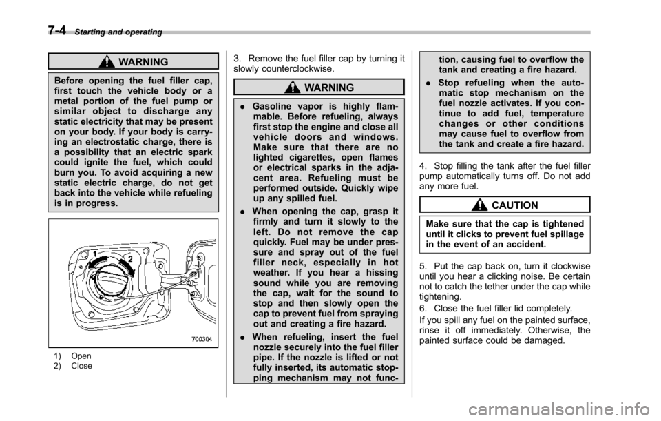
3. Remove the fuel filler cap by turning itslowly counterclockwise.
WARNING
.Gasoline vapor is highly flam-mable. Before refueling, alwaysfirst stop the engine and close allvehicle doors and windows.Make sure that there are nolighted cigarettes, open flamesor electrical sparks in the adja-cent area. Refueling must beperformed outside. Quickly wipeup any spilled fuel.
.When opening the cap, grasp itfirmly and turn it slowly to theleft. Do not remove the capquickly. Fuel may be under pres-sure and spray out of the fuelfiller neck, especially in hotweather. If you hear a hissingsound while you are removingthe cap, wait for the sound tostop and then slowly open thecapto prevent fuel from sprayingout and creating a fire hazard.
.When refueling, insert the fuelnozzle securely into the fuel fillerpipe. If the nozzle is lifted or notfullyinserted, its automatic stop-ping mechanism may not func-
tion, causing fuel to overflow thetank and creating a fire hazard.
.Stop refueling when the auto-matic stop mechanism on thefuel nozzle activates. If you con-tinue to add fuel, temperaturechanges or other conditionsmay cause fuel to overflow fromthe tank and create a fire hazard.
4. Stop filling the tank after the fuel fillerpump automatically turns off. Do not addany more fuel.
CAUTION
Make sure that the cap is tighteneduntil it clicks to prevent fuel spillagein the event of an accident.
5. Put the cap back on, turn it clockwiseuntil you hear a clicking noise. Be certainnot to catch the tether under the cap whiletightening.
6. Close the fuel filler lid completely.
If you spill any fuel on the painted surface,rinse it off immediately. Otherwise, thepainted surface could be damaged.